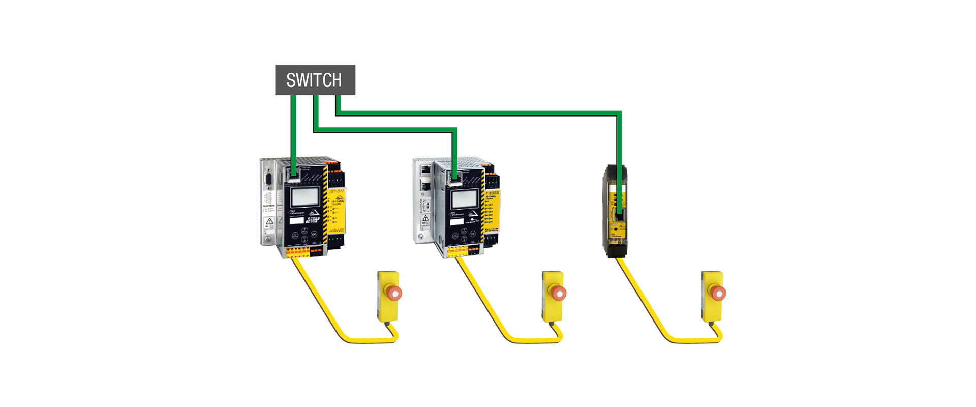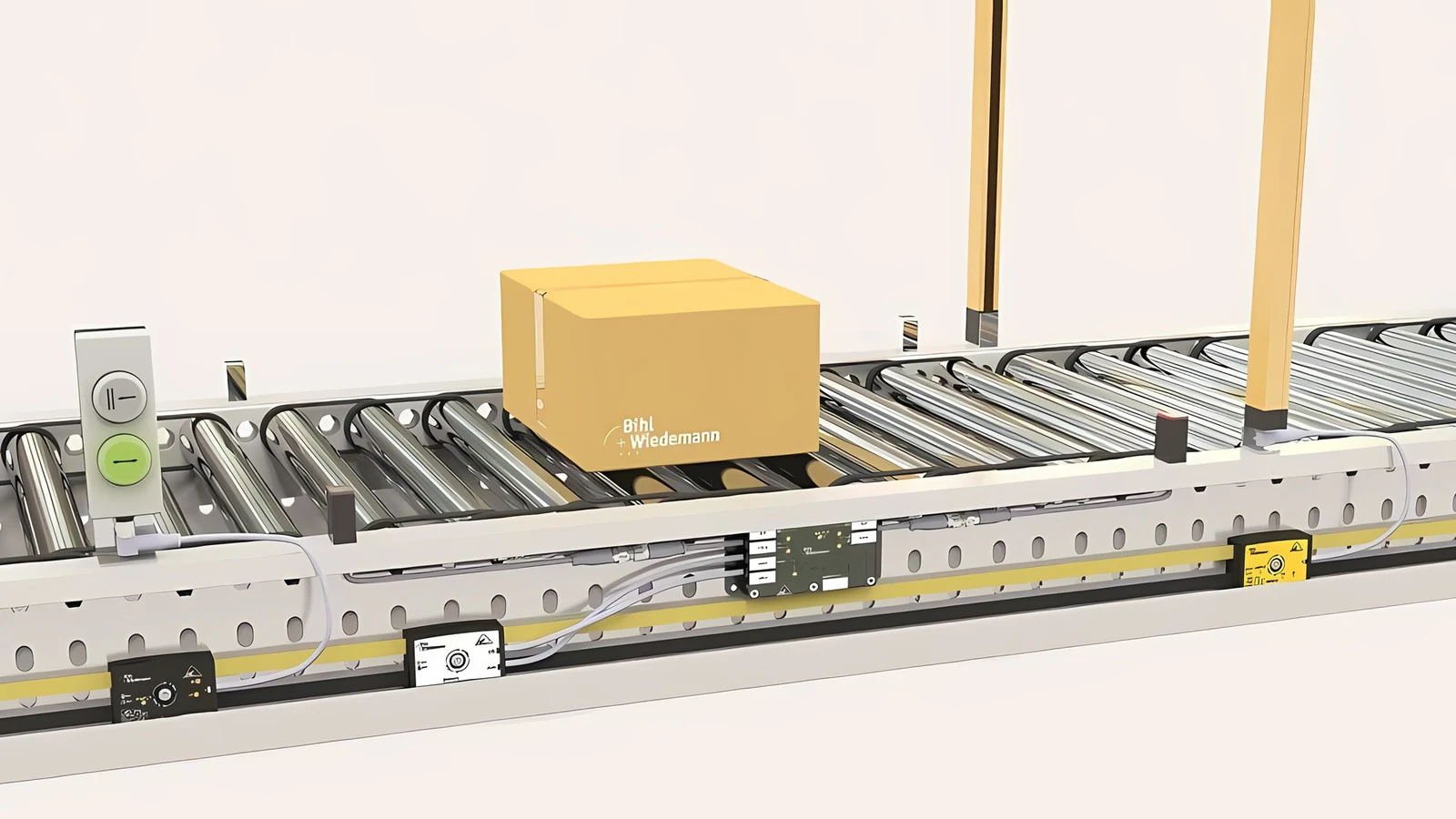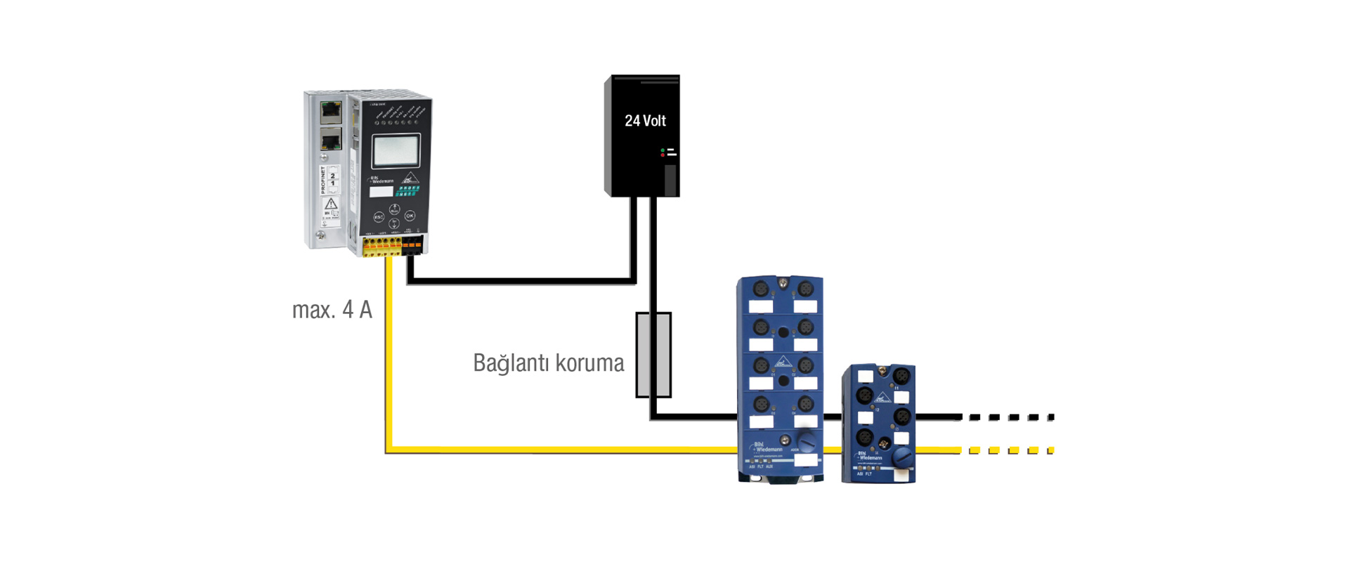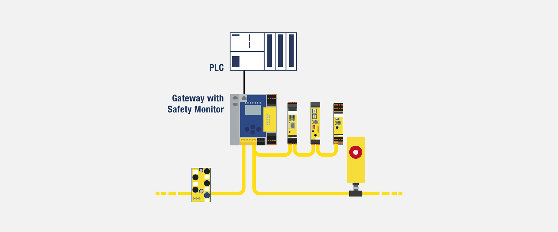
The term “PLC-independent safety technology” does not mean that a machine can operate without a PLC or that safety functions are completely separated from production control. The fundamental approach here is to separate the tasks of evaluating safety sensors, executing safety logic, and managing safety outputs from the high-level standard PLC, regardless of the brand or field network used. This enables the maintenance of the AS-i field layout and a significant portion of the safety functionality, even if the machine’s process control system is changed. Nevertheless, each project must be assessed individually, taking into account factors such as risk assessment, the selected product variant, interface limitations, and verification requirements.
Where does independence begin and end?
In a traditional architecture, standard inputs/outputs and safety signals can be integrated at different control levels within the same manufacturer’s products. When the control platform is changed, field modules, safety programs, and engineering tools can be reconfigured accordingly. Bihl+Wiedemann’s approach that does not rely on PLCs separates safety functionality from the main control system in its official implementation guidelines. The ASi field system transmits process data to the relevant PLCs via gateways compatible with common fieldbus protocols. Safety sensors and actuators are connected to the ASi network, while the safety configuration is prepared in the ASIMON360 environment for use by the Safety Monitor.
This distinction is not absolute. A standard PLC continues to manage machine sequences, HMI messages, and production conditions. A safety monitor may also retrieve certain standard process data to ensure the proper authorization is in place. However, the transition to a safe state should not rely solely on the timely activation of standard PLC bits. The safe inputs, logic, and outputs of a safety function must be properly evaluated within the selected safety architecture. It is essential to clearly identify which data is merely for diagnostic purposes and which signals are actually critical for ensuring safety.
| Architecture | Suitable application scope | Limit to consider |
|---|---|---|
| Basic Safety Monitor | For small or standalone machines: local safety inputs/outputs and ASi extensions. | The Fieldbus interface, the number of local channels, and the need for network expansion are selected according to the specific model. |
| Standard fieldbus gateway + integrated Safety Monitor | Keeping the safety logic within the gateway and transferring diagnostic data and process information to the standard PLC. | Standard fieldbus data is not inherently assumed to enable secure communication. |
| Gateway with support for safe fieldbus systems | Distributed systems that require secure data exchange with high-performance F-CPUs. | The responsibilities of local logic, which is independent of the PLC, and those of the F-CPU should be clearly separated. |
| Monitors connected via Safe Link | Safe interconnection between machine components equipped with different control systems | The region boundaries, data ownership, network load, and error response mechanisms are all verified. |
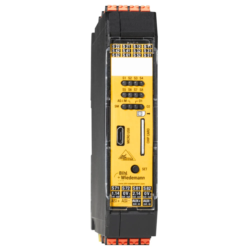
Local safety control for small machines: BWU2700
On the official product page for the BWU2700, it is described as a Safety Basic Monitor with extended functionality and also as an ASi-3 master. This full-range model is equipped with local terminals that can be used as either eight standard digital inputs or four dual-channel safety inputs, as well as two electronic safety output circuits. It can be expanded to support up to 31 dual-channel safety inputs via the ASi interface. Some of the inputs can also be configured for safe speed monitoring using approach sensor signals. Configuration and diagnosis are performed via the Micro-USB interface, and the device boasts a protection class of IP20.
This product can serve as a starting point for establishing local safety controls independent of a standard PLC in a stand-alone system that incorporates multiple safety functions. For example, functions such as emergency stop, protective doors, reset, two safety outputs, and status communication to the standard PLC can all be managed within the same control panel. However, the term “small controller” does not imply that the associated risks are low. Although the product page indicates compatibility for applications up to Category 4/PL e/SIL 3 for local safety inputs and outputs, the actual level of safety achieved is proven through the selected sensors, output components, and the comprehensive functional calculations performed.
Operating benefits of local control
When the safety logic is implemented on the station control panel, changes to the process configuration in the main PLC software do not directly affect the safety settings. If a machine module is moved to another line, the standard communication interface can be reconfigured; local safety functions can be preserved through proper change management. This approach enables standardization in series machine production. To achieve this, the version of the reference safety project, the list of devices, ASI addresses, checksum, validation tests, and permitted settings must all be managed as a cohesive package.
Local safety control is not intended to ignore failures of the main PLC. When PLC communication is lost, it is necessary to analyze how the machine will remain in its current state, how the automatic cycle can be terminated, and whether any unexpected movements may occur once communication is reestablished. Even if the safety monitor maintains the safe output active, the loss of process control can still pose additional risks. Therefore, separate safety or standard response mechanisms are defined for communication timeouts and process failures.
A controller-brand-independent field layer through a gateway
In machines that require communication with higher-level systems, the ASi gateway with integrated safety monitoring functions serves as a bridge between the field network and the PLC fieldbus. Bihl+Wiedemann’s official PLC-independent website explains that it is possible to select protocols compatible with different controllers, and that the basic installation approach using the two-conductor profile cable and field modules from the ASi system is retained. Instead of treating each ASi module individually as a separate fieldbus node, the PLC can access process and diagnostic data via the gateway. This approach can help reduce the number of nodes in the higher-level network and minimize hardware dependencies.
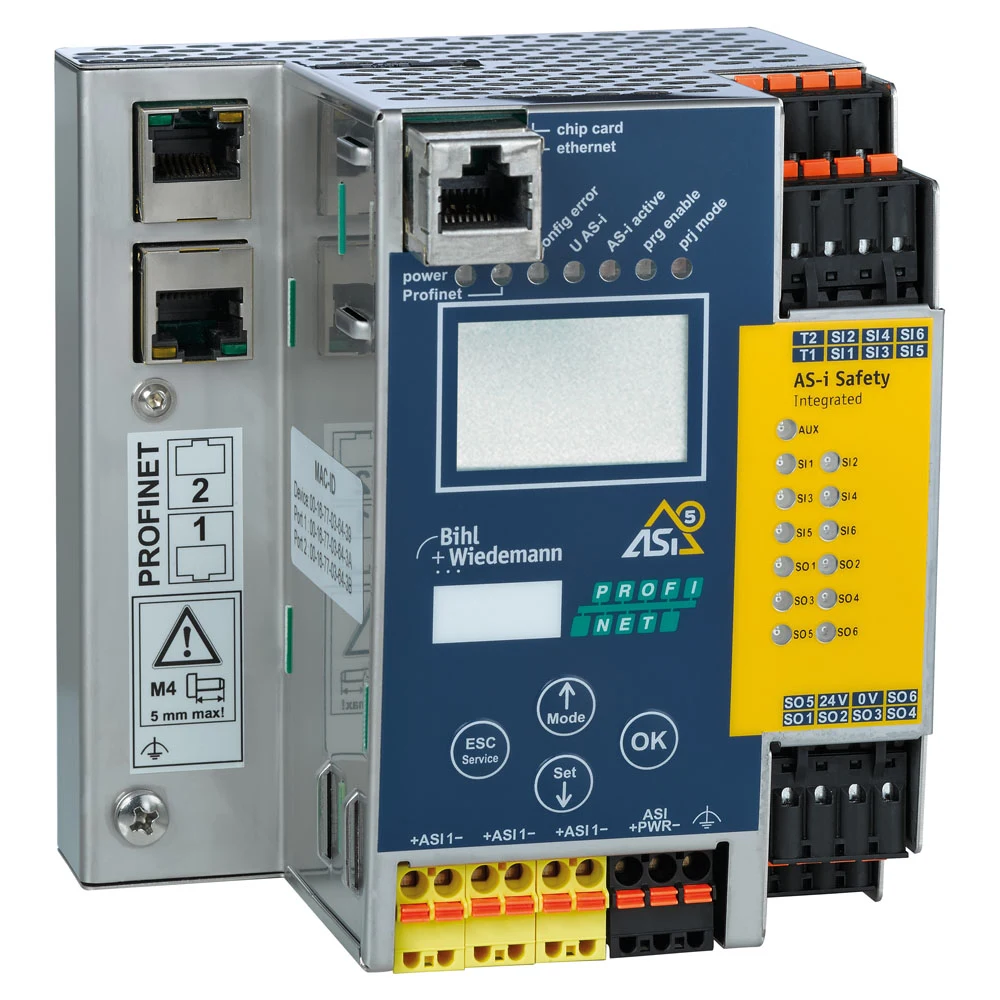
BWU3954 illustrates a safety-fieldbus gateway with one ASi-5/ASi-3 master, an integrated safety monitor, PROFINET, PROFIsafe connection to an F-CPU and Safe Link. Depending on configuration, it has six single-channel or three dual-channel safety inputs and six electronic safety outputs. OPC UA, REST API and a web server provide additional diagnostic and maintenance access. These interfaces do not make all data safety-related: distinguish their diagnostic data from PROFIsafe safety data in the functional design.
Does a safe fieldbus remove independence?
No; however, the distribution of responsibilities changes. When safe data communication is established between the F-CPU via PROFIsafe, some safety functions can be executed on the higher-level safety controller, while others can be handled by the local Safety Monitor. This flexibility allows designers greater freedom in their designs, but it is essential to ensure that no implicit dependencies arise between the two platforms. The location where each safety signal is generated, evaluated, and converted into an output is specified in the safety requirement specifications. In the event of a network disruption, the response times of both parties, the validity of data transmitted upon reconnection, and the functionality of the initial handshake process must all be tested.
Independence from PLCs, in its strongest sense, refers to the ability to verify local safety functions without the use of standard PLCs or F-CPUs. If the safety authorization function originates from a higher-level F-CPU, then the system becomes dependent on that higher-level controller for that specific authorization. This is not incorrect in itself; rather, it is essential to use the correct terminology in such contexts. The goal is not to avoid using a particular brand, but rather to establish a safety layer that features clearly defined interfaces, is maintainable, and can be reused in various applications.
An archived product example for installed systems: BWU3960
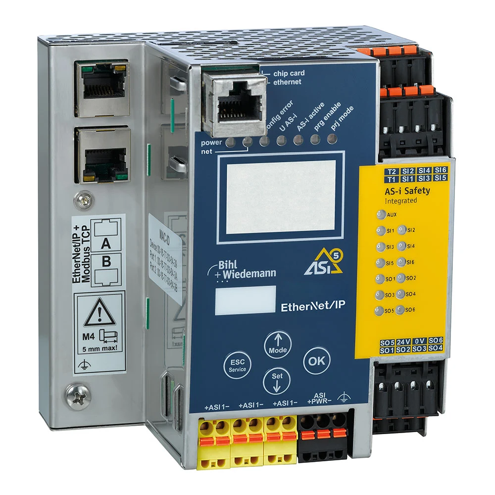
On its official product page, the BWU3960 is described as an ASi-5/ASi-3 EtherNet/IP + Modbus TCP gateway integrated with a Safety Monitor; however, on the manufacturer’s current product list, it is categorized under “Archive Safety Monitors, Safety Ethernet/IP+ModbusTCP.” Therefore, for new projects, it should not be considered an active standard option, but rather an archived product that may be relevant in cases involving existing installations, service requirements, or modernization efforts. This variant, which uses an ASi-5/ASi-3 master, allows ASi field data to be transmitted to higher-level systems via EtherNet/IP or Modbus TCP, and it integrates into the safety architecture via local safety inputs/outputs and Safe Link. For new investments, it is essential to confirm with the manufacturer that the selected variant is current and still supported. Gateways with different protocols or different numbers of masters, even if they share the same housing, cannot be used interchangeably in terms of their order codes.
Such a gateway can facilitate the adaptation of the same machine platform to different customers’ PLCs. While the ASi address scheme, safety modules, and Safety Monitor configuration remain unchanged, the EDS, data structure, and PLC function blocks can be modified at the higher network level. However, a “plug-and-play” approach should not be assumed. The byte order, data length, connection cycle time, timeout settings, connection owner information, input/output words, and diagnostic bits must all be verified on the target PLC. It should also be remembered that standard EtherNet/IP or Modbus TCP data does not inherently possess safety features.
Connecting different control sections with Safe Link
In large facilities, not all machine sections may use the same PLC brand or the same fieldbus system. Bihl+Wiedemann’s Safe Link approach enables the secure exchange of signals over Ethernet between compatible Safety Monitors and gateways. This means that information such as emergency stop commands, safety status reports from adjacent areas, or permission signals at transfer points can be transmitted independently across different control systems. The official product documentation states that up to 31 devices can be connected via Safe Link; however, the actual maximum capacity should be verified based on the specific devices selected, the configuration settings, and the latest technical documentation.
A secure connection must not be implemented in the same manner as ordinary Ethernet traffic connected to any port of the facility’s network. The supported topology, network devices, IP addressing scheme, redundancy approach, as well as response mechanisms for delays and failures must all be configured in accordance with the product specifications. It is essential to verify how other areas can continue operating in the event of a failure in one section, how access permissions are restored once the line is reconnected, and the scope of any maintenance bypass options available. In systems where machines are operated by different teams, having a clear interface agreement and established procedures for collaborative modifications is just as important as adopting the right technical solutions.
ASIMON360: distinguish configuration from programming
The logic for safety monitoring is established within the ASIMON360 software. Function blocks, inputs, restart commands, time conditions, EDM (external device monitoring), and outputs can all be combined within a graphical interface. Although it serves as a useful engineering tool, it does not relieve the user of the responsibility for ensuring safety compliance. The expected safety behavior of each block is first specified in the requirement document; the configuration process then ensures that these requirements are met. Live data displayed during online diagnostics can assist in the commissioning process, but the test protocol should not rely solely on screen images.
Authorization and version control are essential. It is necessary to record who made changes to the safety project, which device software was used for compilation, when it was downloaded, and which verification tests were conducted. Even if the gateway’s backup mechanism facilitates device replacement, automatic transfers are not allowed without verifying the same product number, compatible firmware, and the correctness of the project settings. A version relationship must be established between the standard PLC program and the Safety Monitor project; it is also crucial to check whether changes to the signal names or data structures on one side affect the other side.
Diagnostics, web interfaces and IIoT data
The web server on the gateway can provide information such as OPC UA or REST API data, ASi network status, cycle information, and device diagnostics to maintenance personnel or higher-level systems. This enables faster detection of issues such as cable failures, address conflicts, auxiliary power losses, or specific channel errors. However, diagnostic access and safety control functions are not the same thing. The read-only maintenance interface, write permissions, network segmentation, user accounts, and remote access policies are all determined in conjunction with the facility’s cybersecurity guidelines.
A green indicator on an IIoT screen does not prove that a safety function has been physically tested. Safety verification is accomplished by actuating the actual sensor, disconnecting the communication, and monitoring the feedback from the final switching component. Diagnostic data further enhances the record of this testing process. The synchronization of event timestamps across the PLC, gateway, and maintenance system facilitates the analysis of root causes.
Commissioning scenarios
- Independent testing: In the case of a standard PLC, before it is actually connected to the circuit, each input and safe output connected to the Safety Monitor is tested according to the defined function.
- Interface testing: The status signals sent to the PLC and the standard permission signals generated by it are verified bit by bit; reverse logic and the use of previous data values are also tested.
- Network loss: interruptions in ASi, fieldbus, and Safe Link systems are generated separately; for each, safe and standard output behaviors are recorded accordingly.
- Energy recovery: It is confirmed that when the gateway, the field module, and the PLC are turned on in different sequences, no unexpected restarts occur.
- Device replacement: For spare units with the same product number, the address and configuration are transferred; thereafter, the functional tests are repeated.
- Load test: Response times and diagnostic access are monitored under conditions close to the maximum number of nodes and communication loads.
Quotation and standardisation checklist
- Risk assessment: The PLr/SIL target, safety status, and response time of each safety function.
- Whether a local safety basic monitor is required, an integrated monitoring gateway, or a connection to an F-CPU.
- Upper fieldbus protocol, safe communication protocol, number of masters, and limitations of ASi networks
- Number of safe/standard inputs and outputs, types of OSSD (semiconductor-based safe output signals) and contacts, power and output loads for AUX connections
- Signals to be shared via Safe Link, the number of devices involved, the topology, timeout settings, and regional fault response mechanisms.
- PLC data map, GSDML/EDS/XDD format, data ownership, and diagnostic message standards
- ASIMON360 project version, authorization, checksum, backup and restoration procedure
- Network segmentation for Web, OPC UA, and REST access, user roles, and change logging.
- FAT/SAT scenarios, measured stop times, error injection, and periodic testing plans.
The value of PLC-independent safety technology lies not in merely moving safety functions into some unspecified “black box,” but rather in clearly separating field connections, safety logic, and higher-level control interfaces into distinct layers. Bihl+Wiedemann’s Safety Monitor and gateway portfolio offer various options for adapting these layers to different control systems. Successful implementation relies on a thorough selection of components, a clear definition of responsibilities, and thorough testing using actual fault scenarios.