Not all signals between a controller and field devices are suitable for direct connection. It may be necessary to convert measurement signals, provide electrical isolation, amplify digital outputs, switch loads reliably, or control the direction of motor operation and its protection functions. Phoenix Contact’s interface technologies and switching devices offer dedicated product families for these tasks, including signal conditioners, electromechanical and solid-state relays, monitoring and timing relays, logic and communication modules, as well as CONTACTRON motor control solutions.
The right choice cannot be made solely based on the input voltage or contact current. Factors such as whether the signal is analog or digital, the required electrical insulation, the switching frequency, the type of load, the starting current, the behavior in the event of a fault, the functional safety requirements, and the environmental conditions within the control panel must all be taken into consideration. This catalog guide explains in which applications various product families are suitable; the numerical values provided are specific to the Phoenix Contact product mentioned or to the official product family concerned. The final order code must be verified against the current data sheet, compliance documents, and the risk assessment of the specific application.
What does the interface layer do?
In an automation panel, the interface layer ensures that field signals can be transmitted to the control system in a usable format and that controller commands can be safely executed at the load side. In analog measurement circuits, the primary objectives are often to match different signal levels, minimize the impact of potential differences, and maintain the reliability of measurements in noisy environments. On the digital output side, the focus is on enabling the switching of loads that cannot be directly controlled by the PLC channel, creating potential separation, or providing a replaceable relay interface during maintenance.
Grouping these functions under a single general term such as “relay” may lead to design errors. An analog transmitter, an electromechanical contact, a solid-state output device, and a motor controller each operate based on different principles and exhibit distinct fault behaviors. Details such as contact wear, leakage current, minimum load capacity, response time, switching frequency, short-circuit protection mechanisms, and thermal loads vary depending on the product type. Therefore, when preparing a signal list, it is essential to specify not only the number of channels but also the electrical characteristics and functional roles of each channel.
MINI Analog Pro and MACX Analog for analogue signals
Phoenix Contact positions signal conditioners and measuring transducers as interfaces that isolate, transform, filter, and amplify signals between the field equipment and the controller. The MINI Analog Pro series is ideal for applications with limited space in control panels, as well as various standard, Ex, and safety applications. The MACX Analog series is designed for standard or process applications that require extensive functionality and certification options. However, the presence of the Ex or SIL designation at the family level does not imply that all order codes within the family possess the same level of certification. For applications in hazardous areas, safety-related circuits, or marine projects, it is essential to verify the certification of the specific products selected.
When selecting an analog interface, it is first necessary to define the input and output signal ranges. For example, a current signal ranging from 4 to 20 mA received from the field can be adjusted to fit within the range accepted by the control card; a bipolar voltage signal can also be converted to correspond to another voltage or current range. Subsequently, factors such as the requirement for two- or three-way isolation, the type of active or passive output, the power supply method, the desired transmission accuracy, the response time, and the ambient temperature must be taken into consideration. The use of DIN rail connectors for common power supplies in multi-channel control panels can reduce the number of separate power circuits required; however, the maximum number of modules that can be connected must be calculated based on the current consumption of the individual products.
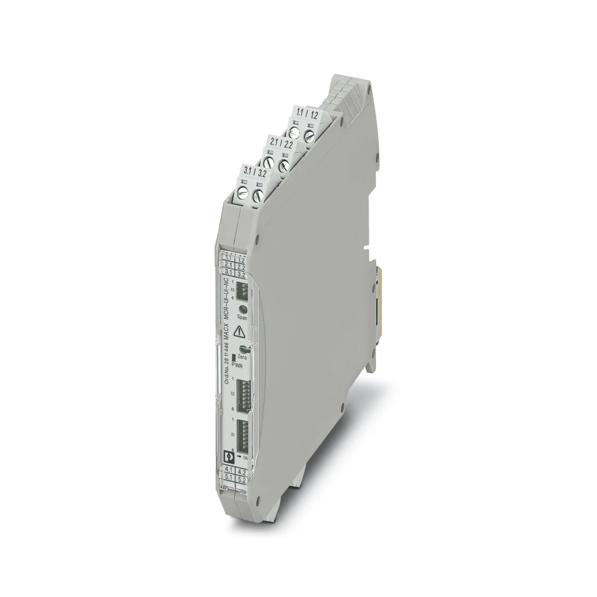
Product example: MACX MCR-UI-UI-NC
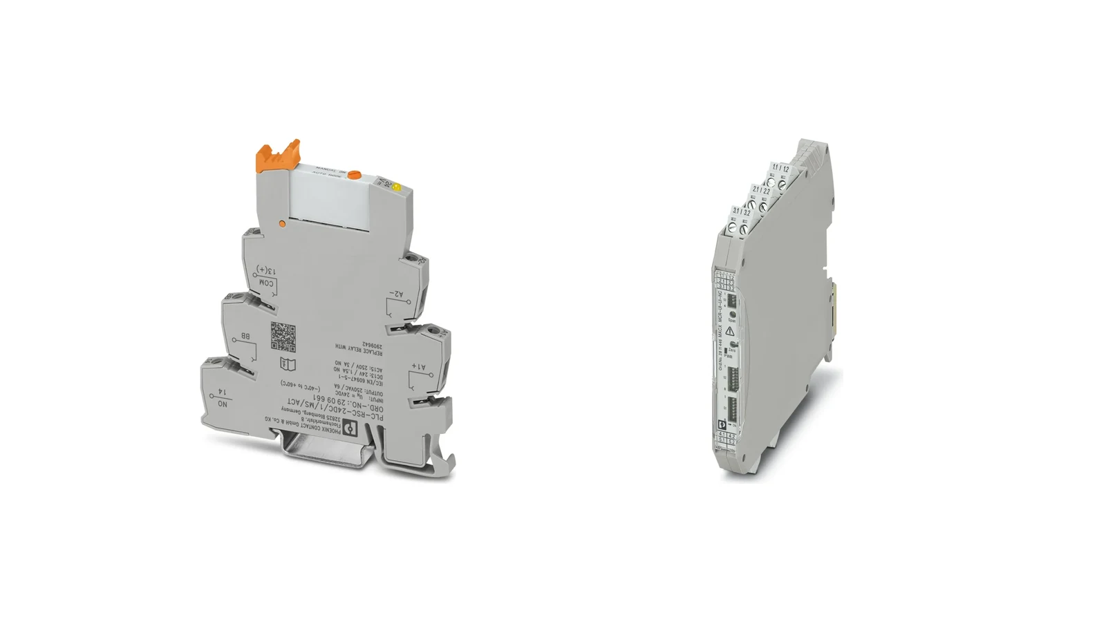
The MACX MCR-UI-UI-NC with the product number 2811446 is a single-channel, three-way isolation amplifier that can be configured using DIP switches. According to Phoenix Contact’s product page, it supports more than 1,600 different signal conversion settings. The standard configuration provides an input range of 0–10 V and an output range of 0–20 mA, with electrical isolation between the input and output signals. The device’s nominal operating voltage is specified as 12–24 V DC, while the allowable voltage range is 9.6–30 V DC. It should be noted that these specifications apply specifically to this particular product code and not to all MACX models.
For the same product, the limit frequency of 10 kHz can be switched to 30 Hz; the manufacturer specifies a typical response time of 35 µs at 10 kHz and 11 ms at 30 Hz. The maximum transmission error is stated to be 0.1% based on the final value; the total width of the device is 12.5 mm, and its operating temperature range is −20 to +70 °C, making it suitable for use at altitudes of up to 2,000 meters. The product page also indicates that it complies with SIL 2 standards according to IEC 61508. However, compliance with SIL standards does not solely depend on the device label itself; the architecture of the safety function, its scope of application, error rates, and operating conditions must also be taken into consideration within the overall system design.
PLC-INTERFACE relay interfaces between controller and field
PLC-INTERFACE is a compact relay system used for signal switching, isolation, and signal amplification between controllers and system I/O components or field devices. Phoenix Contact offers a range of electromechanical and solid-state relay modules within this family, along with input/output functions, specialized contact configurations, and various accessories. The modular remote control relay system enables PLC-INTERFACE terminals to be connected to networks such as PROFINET, EtherNet/IP, and Modbus/TCP. The official product page specifies that the maximum configuration allows for 56 I/O channels; however, this capacity is determined by the limitations of the associated network gateway and expansion architecture, and cannot be assigned individually to each PLC-INTERFACE module.
In a relay interface, the coil or input voltage is connected to the PLC output, while the contact side is matched with the actual load. The maximum value specified for resistive loads cannot be directly applied to inductive loads, contactor coils, or capacitive inputs. For DC coils, the suppression circuit must be considered; for AC and DC loads, the relevant application category must be taken into account. In the case of frequent switching, the electrical life of the components and the thermal effects on adjacent modules also need to be evaluated. A socketed design can facilitate maintenance; however, it is essential to use the same contact material and coil version during replacement.
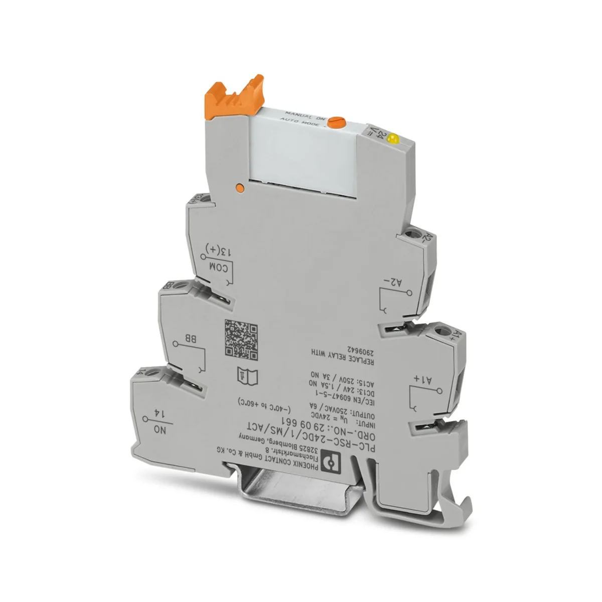
Product example: PLC-RSC-24DC/1/MS/ACT
The PLC-RSC-24DC/1/MS/ACT with the product number 2909661 is a PLC-INTERFACE module that contains a miniature relay with a 24 V DC input, screw connections, and manual operation. The product page specifies that it features a normally open contact, a continuous current rating of 6 A, a width of 6.2 mm, and an operating temperature range of −40 to +60 °C. The manufacturer also provides data indicating an input voltage range of 18.5–33.6 V DC at 20 °C, a typical response time of 5 ms, and a release time of 8 ms. These specifications should not be applied to other coil, contact, or connection variants within the PLC-RSC family.
While the product is specified to have a maximum switching voltage of 250 V AC/DC, the page also indicates that a partitioning plate is required between adjacent modules under certain voltage conditions. The power ratings provided for resistive loads, as well as the application categories for AC-15/DC-13, also differ from each other. This example illustrates why simply stating “6 A relay” in the selection table is insufficient: the load’s voltage, current type, application category, starting current, switching frequency, fuses, and the layout of adjacent channels must all be taken into consideration.
Electromechanical or solid-state relays?
Electromechanical relays use physical contacts to perform switching operations and provide galvanic isolation when the contacts are open. Due to their various contact configurations and the ability to handle AC/DC loads, they are versatile for general-purpose applications. However, the electrical lifespan of their contacts depends on the actual load and the frequency of switching. Solid-state relays, in contrast, do not rely on moving parts and therefore excel in applications requiring fast and high-frequency switching. Nevertheless, characteristics such as voltage drop when closed, leakage current when open, thermal losses, and the specific direction of current or type of load must be carefully evaluated for each individual product.
When making a selection, general terms such as “maintenance-free” or “long-lasting” are not sufficient. Valve coils, signal lamps, resistors, contactor coils, and electronic components exhibit different load behaviors. The leakage current of a solid-state output can cause a sensitive input device to malfunction; whereas very low currents in electromechanical contacts may lead to the breakdown of reliable contact connections. Decisions should not be based solely on nominal currents, without considering the actual current values in the load and the characteristics of the suppression components involved.
When are monitoring and timing relays used?
EMD monitoring relays are designed to independently monitor parameters such as excessive or low voltage, excessive or low current, phase loss, phase sequence, phase imbalance, power factor, active power, motor winding temperature, and fill level. These devices can be utilized when it is necessary to check simple conditions independently of PLC software, transmit fault signals to the control system via dry contacts, or shut down specific sections. The parameters available on a single device and the range of threshold settings vary depending on the order code.
For example, the EMD-BL-PTC with the model number 2906252 is designed to monitor the motor winding temperature and detect short circuits in the thermistor circuit, and it can accommodate up to six PTC elements in compliance with DIN 44081 and DIN 44082 standards. This device is not a general-purpose temperature controller; the connection of the PTC elements and the sensor configuration specified by the motor manufacturer must be verified. Time relays, on the other hand, can perform simple timing functions such as starting, stopping, triggering, or cycle control. Phoenix Contact offers a wide range of time control products, with timing ranges extending from a few milliseconds to several days; the specific range and functionality of a particular time relay should be confirmed on its data sheet.
Motor switching and protection with CONTACTRON
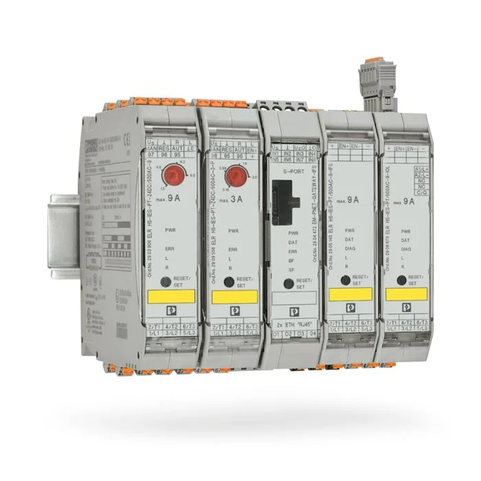
The CONTACTRON product range includes dedicated solutions for directly or inversely controlling three-phase AC motors, switching and reversing DC motors, performing various speed and acceleration control tasks, or protecting loads in modern DC power systems. Hybrid motor controllers combine semiconductor-based and electromechanical switching technologies. The official product page outlines that these standalone hybrid controllers are designed for controlling and reversing asynchronous motors with powers ranging from 50 W to 3 kW. Key features include a width of 22.5 mm, adjustable motor protection capabilities up to 9 A, and in certain versions, SIL 3/PL e safe-stop features.
Within this range, the same product code is not used for all power levels. The motor’s label current, grid voltage, requirement for direction change, starting time, switching cycle, coordination type, short-circuit protection, and selected safety function all determine the appropriate product code. For network-connected options, parameter and diagnostic data transfer via IFS or IO-Link may be possible; the specific communication protocol supported must be verified based on the selected variant and the network gateway used. The emergency stop function is also confirmed not only by the presence of the device itself but also through the machine’s risk assessment and the entire safety chain.
Compare product families by function
| Application task | Phoenix Contact family to consider | Information that determines the decision |
|---|---|---|
| Isolating or converting analog measurements | MINI Analog Pro or MACX Analog | Input/output range, insulation, accuracy, response time, Ex classification/SIL rating, and power supply. |
| Separating the PLC output from the load | PLC-INTERFACE or RIFLINE complete set | Coil voltage, contact configuration, load category, current, and replaceability |
| Switching at high frequencies | Appropriate solid-state relay module | AC/DC direction, leakage current, voltage drop, thermal loss, and frequency |
| Monitoring the status of the system or the motor | EMD monitoring relay | Measured parameter, threshold, delay, output contact, and supply |
| Creating simple time sequences | Time-delay relay | Function, time interval, setting accuracy, and contact load |
| Starting, reversing, and protecting the motor | CONTACTRON motor starter | Motor type, power and current, direction, starting, protection, communication, and safety. |
Details to consider in panel design
When interface devices are arranged on a DIN rail, the total width alone should not be the only factor considered. The distance between cable channels, the space required for connectors or relays, the use of partition plates, as well as measures to reduce heat generation and ensure proper air circulation when devices are mounted side by side, must all be taken into account in accordance with the manufacturer’s instructions. The use of common bridges can speed up the installation process; however, it is essential to establish clear color-coding, separation, and labeling standards to prevent accidental cross-connection of different circuits. The channel number, PLC address, field label, and product function should all be consistently documented within the same project.
In a project that requires functional safety or explosion protection, the product family’s promotional materials do not constitute design documentation. Certificates related to the specific order code, safety instructions, usage restrictions, and current revision documents must be included in the technical documentation. The SIL or PL rating does not mean that the device alone confers this level of safety to the entire machine. Similarly, an Ex certification cannot be deemed valid without specifying the connection type, area of use, gas group, temperature class, and environmental conditions in which the device will operate.
Information required for quotations and project planning
- Source signal, target signal, nominal value, and allowable error for each channel
- For analog channels, the input/output range, active-passive configuration, insulation levels, and response times are important specifications to consider.
- In digital circuits, the PLC voltage, load voltage, AC/DC type, and actual load characteristics are all relevant parameters.
- Contact configuration, minimum and maximum load, starting current, and number of switchings per hour.
- The rationale for choosing between electromechanical and solid-state technologies in terms of maintenance requirements, speed, leakage current, and heat generation.
- Threshold and delay values set according to the desired parameters such as voltage, current, phase, temperature, or time.
- Motor labels indicate information such as power, current, line voltage, direction of rotation, and starting profile.
- The required SIL, PL, or Ex classification, as well as the risk assessment specific to the application.
- Panel temperature, mounting height, vibration, contamination class, and certification requirements.
- Connection technology, common power supply, bridging, marking, and spare parts standards.
The interface list prepared using this information transforms the product selection process from a simple catalog search into a systematic engineering decision-making process. Oskon can analyze the entire chain – from field signals to PLC channels, from control outputs to actual loads – to determine the appropriate Phoenix Contact product family and the exact order code required. Before commissioning, it is essential to record the connection diagram, protective components, torque values, functional tests, and, where necessary, safety certifications.