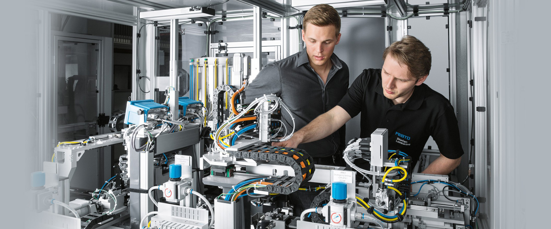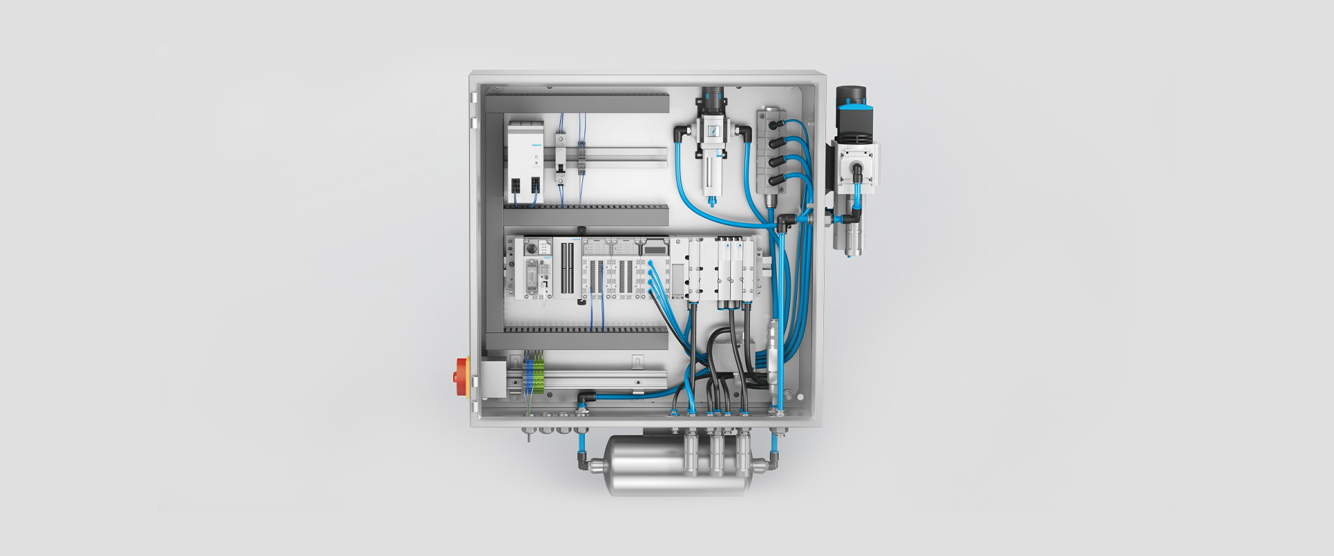
The reliability of a pneumatic axis is not determined solely by the cylinder diameter. Factors such as the direction of the load, stroke length, cycle time, external forces, bearing conditions, valve function, actual flow rate, hose volume, cushioning system, position feedback, and the quality of compressed air are all essential components of the same system design. This catalog and selection guide focus first on the motion requirements of each application when discussing Festo’s pneumatic drive and control components. The technical specifications provided apply only to the examples specifically identified by their name and product number. For final selection decisions, it is essential to refer to the latest Festo data sheets, operating instructions, risk assessments, and the actual operating conditions of the machinery in question.
Start selection with the motion task, before the product code
The first step is to digitally define what the mechanism is intended to do. Information such as the forward and reverse loads, vertical or horizontal mounting, stroke length, target time, number of cycles per hour, waiting times, and the risk of impact must be recorded separately. Even if the horizontal axis that pushes a component and the vertical axis that lifts and holds a load have the same diameter, they do not necessarily have the same safety and control mechanisms. The center of gravity of the load, its distance from the connection point, and the position of the mechanical guides also affect the torque applied to the cylinder.
The theoretical force of a pneumatic cylinder depends on the product of the pressure and the effective piston area. During the return stroke, the area occupied by the piston rod is reduced; therefore, the reverse force generated at the same pressure is lower than the forward force. When factors such as seal friction, guide friction, acceleration, pressure drops along the line, and other losses are taken into account, the theoretical value cannot be directly applied to determine the actual load. The design pressure should not be the instantaneous value at the compressor outlet, but rather the lowest operating pressure that can be maintained at the machine inlet under the condition of maximum simultaneous consumption.
Cycle time is not simply stroke divided by speed. Valve switching, filling the cylinder chamber and hoses, exhausting air, the cushioning zone and control delays all contribute. Increasing cylinder diameter solely to obtain more force can be counterproductive: a larger volume requires more air, a larger valve and longer filling time. The smallest suitable actuator that retains sufficient force reserve often provides a better balance of energy use, motion quality and hardware size.
| Task | Solution to consider | Key data that determines the decision |
|---|---|---|
| Standard linear pushing, pulling, or lifting actions. | Cylinder with piston rods that comply with ISO standards; for example, DSBC. | Force, stroke, installation, piston rod load, cushioning, and sensing. |
| Short, rigid movement under the action of force or torque | Integrated drive system with guidance function; for example, DFM/DFM-B | Guidance type, force-moment combination, stroke length, speed, and braking energy. |
| Linear motion with long stroke and limited mounting height. | Rodless cylinder suitable for the application | Stroke, load being transported, external guide, leaky connections, and the surrounding environment. |
| Rotation or oscillation within a limited angle range | Pneumatic rotary drive | Rotational angle, torque, inertia, braking energy, and mechanical stop. |
| Central pneumatic control for multiple axes | Appropriate valve terminal; for example, VTUG. | Valve functions, total/ simultaneous flow rate, pressure zones, and communication. |
Standard linear motion: DSBC ISO cylinders
Festo’s current technical documentation for DSBC systems defines this product family as cylinders that meet ISO 15552 standards regarding standard dimensions, dual-action functionality, and contactless position detection. The standardized mounting interfaces in the new design facilitate the selection of accessories and the evaluation of mechanical compatibility in existing machines under appropriate conditions. However, the term “ISO-compliant” does not imply that the cushioning properties, sensor sockets, accessory range, or material selection are identical across all manufacturers. Both dynamic performance and environmental characteristics should be compared on a product code level, in addition to installation dimensions.
The DSBC series offers options including elastic end buffers, self-adjusting pneumatic buffers, and adjustable pneumatic buffers. The function of these buffers is to dissipate the energy of moving masses in a manner that is acceptable at the end of each stroke. The speed control valve, on the other hand, regulates the speed of the shaft throughout its movement; these two functions are not interchangeable. In cases where large masses are involved, high speeds are required, or the buffering distance is short, it is necessary to calculate the allowable energy levels and adjustment ranges. If needed, additional external shock absorbers or mechanical stop mechanisms should be considered.
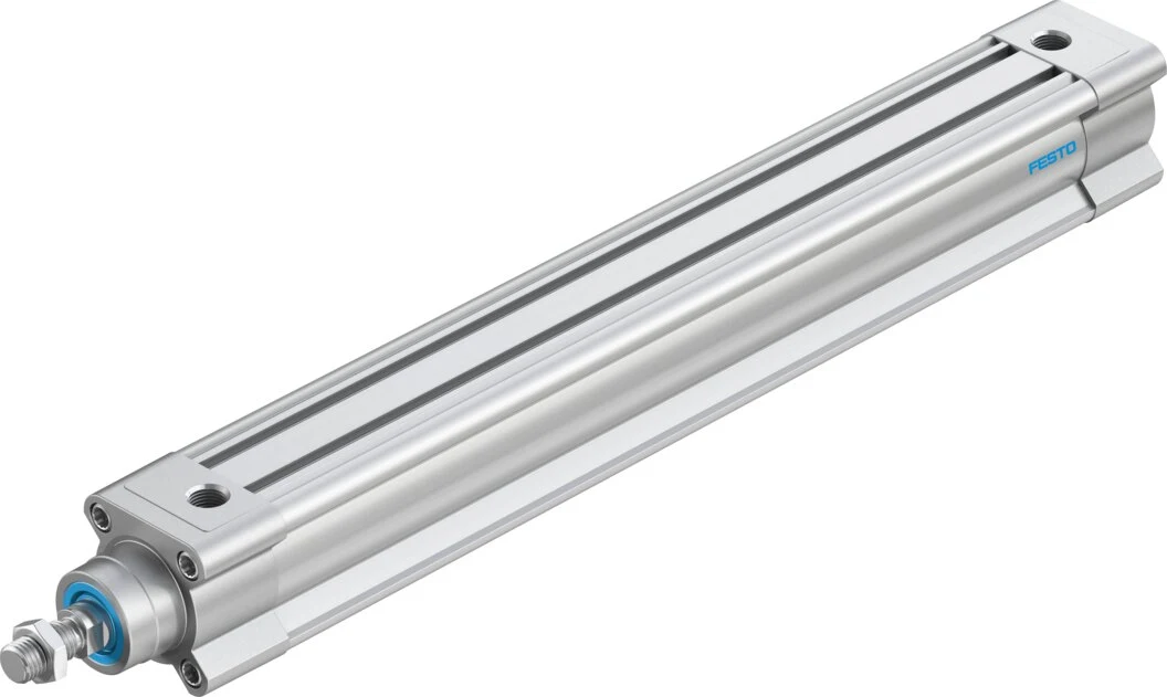
Variant example: DSBC-40-320-PPSA-N3
Festo’s August 2026 data sheet specifies DSBC-40-320-PPSA-N3, product number 1376912, with a 40 mm piston diameter, 320 mm stroke, double-acting operation and self-adjusting pneumatic end-position cushioning. Operating pressure is 0.6–12 bar; theoretical force at 6 bar is 754 N extending and 633 N retracting. It complies with ISO 15552, supports proximity-switch position sensing and has a G1/4 pneumatic connection. These figures apply only to this variant and must not be transferred to other diameters, strokes, cushioning or special-material options.
Even if the piston rod appears to be capable of withstanding the pulling loads during long strokes, its bending limits in the pushing direction must also be carefully monitored. The type of joint or flange used must ensure that the load is aligned with the cylinder axis; the piston rod should not be used as a guide element. Any angular misalignment in the connection, loads applied without proper guidance, or the rigidly connected parallel cylinders can lead to premature wear of the seals and bearings. The assembly drawings must include details of the piston rod connections and the load guiding mechanisms.
Lateral forces and moments: DFM guided drives
Consider an integrated guided actuator when a workpiece must be moved while preventing rotation, carrying a fixture or resisting a moment at the end plate. Festo DFM combines the drive and guide in one housing, with GF plain-bearing and KF recirculating-ball-bearing options. Plain bearings suit high rigidity and impact resistance; recirculating ball guides can suit precision motion and moment loads. Select using load diagrams and the actual cycle, rather than broad labels such as ‘more precise’ or ‘stronger’.
For DFM, the catalog specifies stroke lengths of up to 200 mm; for DFM-B, the range extends up to 400 mm. However, the permissible forces, torques, and speeds depend on factors such as piston diameter, stroke length, guide rails, cushioning systems, direction of motion, and the composition of the simultaneous loads. When interpreting a single maximum torque value in the catalog, it should be assumed that all other torques and forces are zero. In the event of multiple loads acting simultaneously, the manufacturer’s integrated load control system must be utilized; the mass and center of gravity of the device attached to the end plate must also be taken into account.
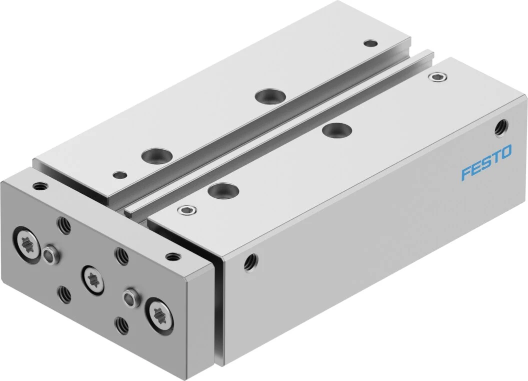
Variant example: DFM-16-50-B-PPV-A-GF
The data sheet for the product DFM-16-50-B-PPV-A-GF, with the product number 8162433, specifies the following specifications: piston diameter of 16 mm, stroke length of 50 mm, double-acting operation, pneumatically adjustable buffers at both ends, and guide rails with sliding bearings. The operating pressure ranges from 2 to 10 bar; the theoretical force at 6 bar is 121 N in the forward direction and 104 N in the reverse direction. Position detection can be achieved using a proximity switch, and the connection thread is M5. It should be noted that these values do not fully determine all the external forces and moments that the actuator can withstand at its end plates; the load diagrams and mounting geometry of the DFM component must also be considered for a comprehensive assessment.
The stopping energy must also be considered separately from the rated capacity. The kinetic energy of the moving component must not exceed the maximum allowable position energy specified in the drive’s catalog. Possible solutions include reducing the permitted speed, decreasing the mass of the component, or adding external shock absorbers. The sensor cable and pneumatic hoses must be routed in such a way that they do not rub against moving parts; centering bushes and connection surfaces must be used in accordance with the installation instructions.
Match valve function to cylinder behaviour
A single-acting actuator is typically controlled by a 3/2-way valve, while a double-acting actuator generally uses a 5/2-way valve or a 5/3-way valve if the task requires it. This is only an initial classification. A monostable valve returns to its spring-defined position when electrical power is lost; a double-solenoid or bistable design may retain its last switching state. Assess axis direction and speed on the circuit diagram for loss of electrical power, air supply or control signal.
A 5/3-way valve may have a closed, exhausted or pressurized center position. These descriptions alone do not guarantee safe mechanical load holding. Air is compressible, valves and cylinders leak, and stored energy remains in the hoses. If a vertical axis requires load holding, controlled lowering or prevention of falling after pressure loss, design mechanical locking, braking, counterbalancing or other measures based on the risk assessment. Festo’s DSBC documentation also states that certain locking options must not be treated as safety-related control elements without additional measures.
The nominal flow rate of a valve should not be selected solely based on the larger value listed in the catalog. The required cylinder speed, the effective piston area, and the volume to be filled determine the necessary flow rate. The valve, cable glands, hoses, mufflers, and the common manifold channels all contribute to the overall flow resistance. If multiple valves need to be activated simultaneously, the total flow rate in the common supply and exhaust channels must be taken into consideration. Even if a valve appears to have sufficient capacity, a small hose or a clogged muffler can still reduce the actual flow rate.
Central control and flexible configuration: VTUG valve terminals
On machines with many pneumatic axes, a valve terminal organizes common air supplies and electrical connections. Festo’s 2026 VTUG documentation lists 2 × 3/2, 3/2, 5/2 and 5/3 functions, valve widths of 10, 14 and 18 mm, and expansion to 24 valve positions depending on configuration. Options include multi-pin, I-Port, IO-Link and fieldbus connection through a CTEU bus node. Verify the actual protection rating, interface and functions against the completed configuration.
Multiple VTUG pressure zones can support different operating pressures or separate pilot-air arrangements on one terminal. Limits depend on the manifold, separating elements, pilot supply and valve type. Requirements such as vacuum operation, external pilot air, control-cabinet installation or hot swapping must be verified beyond the family name. Clearly mark pressure zones on the pneumatic schematic with every working port, supply, exhaust, pilot and silencer connection.
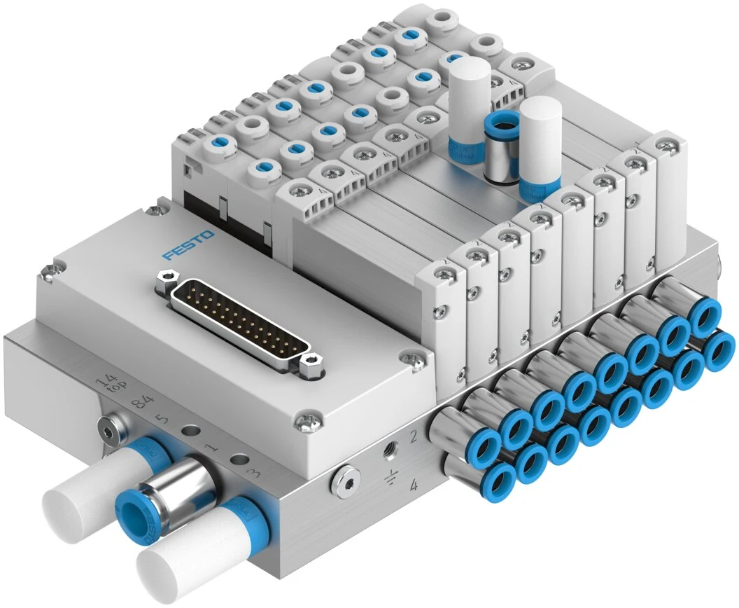
The data page for the VTUG series with product number 573606, as of August 2026, lists the maximum standard nominal flow rates based on various configurations, such as up to 24 valve positions and 13 pressure zones, as well as a nominal operating voltage of 24 V DC. For the 10, 14, and 18 mm sizes, the maximum flow rates specified are 330, 630, and 1200 liters per minute, respectively. However, this does not mean that the terminal will achieve these flow rates in any configuration or when all valves are operating simultaneously. The actual flow capacity must be verified based on the complete product code, valve function, port configuration, common supply/exhaust arrangement, and operating pressure.
Design speed control, cushioning and exhaust paths together
A one-way flow control valve allows free flow in one direction and regulates the flow in the opposite direction. Festo states that these components are used to adjust the speed of pneumatic cylinders. In most applications, restricting the exhaust air in double-acting standard cylinders ensures stable movement by creating counterpressure on the piston’s output side. However, in cases of very low speeds, variable loads, vertical movements, or special processes, a supply-side regulation or proportional control approach may be necessary. The specific application circuit should be determined based on the manufacturer’s documentation and test results.
When the throttle valve is located near the cylinder port, its influence on the hose volume setting may be reduced. The two operating directions must be adjusted separately, and the adjustment mechanism must be secured to prevent unauthorized modifications. If fully opening the throttle valve is not sufficient to achieve faster movement, the problem may lie with the valve itself, the hose, the fitting, the supply pressure, or the exhaust line. Before increasing the speed, it is essential to reevaluate the energy requirements of the moving components, their cushioning capacity, their mechanical design, and any potential safety risks for the operators.
Tubing and fitting selection are part of motion performance
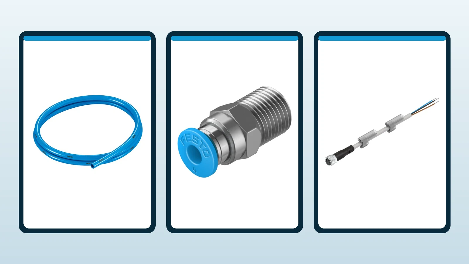
The inner diameter and length of the hose between the valve and the actuator determine both the pressure loss and the dead volume that needs to be filled. A hose with an excessively small cross-section can result in speed losses under high flow rates, while a large and long hose may increase air consumption and response time. Moving the valve closer to the actuator, using a hose with the appropriate cross-section, and avoiding unnecessary hose lengths are often the most effective adjustments that can be made before upgrading to a larger valve. In the case of hoses used in mobile cable carriers, their flexibility, wear resistance, and compatibility with the surrounding environment must also be taken into consideration.
Fitting thread size alone does not determine flow capacity: the internal bore, elbow geometry and installed hose affect the actual cross-section. Match the hose outside diameter to the fitting series, cut it squarely and insert it to the manufacturer’s specified depth. Standard hose–fitting pairs should not be selected automatically for welding spatter, food areas, chemicals, UV, high temperatures or hydrolysis exposure. Festo offers different materials and designs for these environments.
Position sensing and control signals
The cylinder sensor detects the magnetic field generated by the magnet inside the piston and transmits this position data to the control system via the connector. The sensors located at the forward and rear ends can be used to confirm that the movement has been completed, the part has been released, or that the next step of the process can begin. It is not sufficient for the sensor to simply fit physically into the corresponding socket; the appropriate sensor type, switching logic, supply voltage, output configuration, cable connections, and environmental resistance requirements must all be verified to ensure compatibility with the selected actuator.
Set the sensor within a reliable switching window before the mechanical end stop, and test at the worst-case pressure, speed and load. PLC timeout and plausibility checks should detect a missing sensor signal, both sensors active simultaneously or an unexpected intermediate position. For analog position feedback, select a suitable position transmitter and control architecture; two standard end-position sensors do not provide continuous position measurement.
Compressed air preparation: process stability as well as product life
In the current specifications for Festo DSBC, DFM, and VTUG, the working medium is specified as compressed air in accordance with ISO 8573-1:2010 [7:4:4]. However, this does not imply that only one type of filter is sufficient for every application. The particle, moisture, and oil content of the plant air, as well as the ambient temperature, pressure dew point, and the specific requirements of the process, must all be taken into consideration. The filter, regulator, dryer, pressure measuring device, control valve, and soft-start function must be selected according to the capacity requirements of the machine.
The regulator pressure should be set at the lowest level that still provides the required force. Unnecessary high pressure not only increases consumption but may also lead to increased vibration, noise, and component strain. As the filter becomes clogged, the pressure drop increases; therefore, the pressure indicators and maintenance thresholds must be easily accessible. If a product is switched to lubrication, it may be necessary to continue using lubrication according to the recommendations in Festo’s data sheets. The decision to use lubrication should be made in conjunction with the entire maintenance procedure.
Information required for quotations and bills of materials
- Direction of motion, stroke length, mounting position, forward/reverse times, waiting periods, and number of cycles per hour.
- The total mass that is transported and moved, external forces, center of gravity, and the components of force and moment.
- Minimum, normal, and maximum pressures at the machine inlet, axes operating simultaneously, and the current flow rate.
- For cylinders, these components include piston diameter, stroke length, cushioning systems, piston rod ends, mounting accessories, and position sensing devices.
- For guided drives, guide types, combined load calculations, braking energy, and device connections are required.
- Valve function, monostable/bistable behavior, middle position, pilot air supply, as well as the need for vacuum and pressure zones.
- Valve/terminal interface, coil voltage, PLC connection, IO-Link/fieldbus selection and diagnostic requirements
- Length of the hose, outer/inner diameter, couplings, mufflers, flow control valves, and exhaust route.
- Air quality class, temperature, dust, water, chemicals, welding sparks, cleanroom conditions, or explosive environments.
- The expected safe conditions regarding energy and air loss, vertical load, maintenance isolation, and risk mitigation measures.
Commissioning and acceptance testing
Before commissioning, the product codes, flow directions, port numbers, hose diameters, electrical diagrams, and torque values must be recorded in the as-built documentation. The initial pressurization process must be carefully monitored, and the movement generated by the soft-start function should be observed. The pressure regulator is adjusted from the low value to the target pressure; any leaks must be checked, and the manual operation of each valve should only be tested under safe conditions. The cylinder speeds must be adjusted separately in both directions, and the final position, cushioning effects, and sensor switching points must be verified.
During the acceptance test, the axis must complete the specified number of cycles at the minimum system pressure and within the allowable maximum load. Subsequently, by activating multiple consumers simultaneously, pressure drops, movement times, and terminal supply conditions are monitored. Simulations of power or air supply interruptions must be conducted in accordance with established safety procedures, and it must be confirmed that the load and valves operate as expected. Test records should also include data on PLC timeout events, sensor discrepancies, and restart scenarios.
The maintenance plan should include checks for filters and condensate levels, leakage detection, hose wear, gland integrity, silencer blockages, sensor stability, guide clearance, and the surface condition of piston rods. A gradual change in cycle time should not be solely attributed to cylinder failures; instead, pressure, flow rate, exhaust conditions, friction, and load trends should all be examined together. As a result, Festo’s drive and control components are designed as a pneumatic subsystem with measurable performance parameters and identifiable acceptance criteria, rather than as individual components.