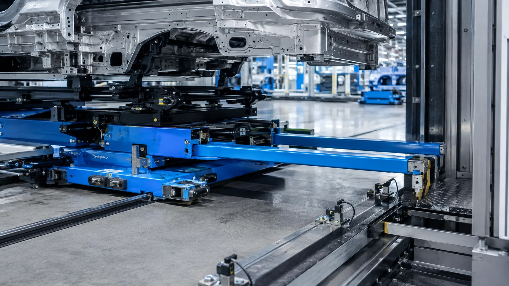
Design load handling, motion envelopes and position verification together for automatic carriers and telescopic bars. Product handover between stations depends on the control interface as well as mechanical compatibility.
The handled load is the starting point for design
The product mass, center of gravity, contact points, and variety of models determine the choice of the carrier. In the case of a telescopic mechanism, not only the closed length but also the range of motion during extension must be taken into consideration. Nearby equipment, the arrangement of cable routing, and maintenance accessibility should also be factored into this consideration. The target cycle time is determined in conjunction with the mechanical capacity, acceleration capabilities, and stopping behavior of the system.
Verify position for each task
Knowing that the carrier is moving does not prove that the load has reached the correct delivery location. Necessary verification steps are defined at the starting, intermediate, and delivery locations. The sensor or position measurement method chosen must take into account mechanical tolerances and operating conditions. When signals that are supposed to verify each other conflict, the system’s behavior must be clear and predictable. The display screen should clearly indicate the expected position and any missing feedback.
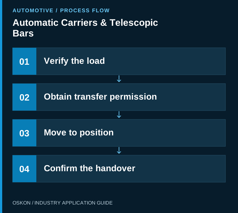
Transfer is a two-sided operation
The receiving station must be able to accept the load as well as the sending station being ready. Manage load presence, mechanical support and transfer-complete signals in a shared sequence. Define timeouts and retries for communication delays or interruptions. Assess restarting incomplete transfers for scenarios such as moving the load twice or leaving it unsupported.
Separate the motion modes
The tasks performed during automatic production, adjustment, maintenance, and fault resolution are different. Permissions and movement restrictions are defined based on the risk assessment of these tasks. A simple confirmation on the standard PLC screen does not suffice to replace the required safety functions. Equipment design must include appropriate recovery procedures in case of power loss, loss of position information, or mechanical jamming.

Mechanical trends provide maintenance data
Longer cycles, changes in drive load or recurring warnings at particular positions can guide maintenance investigation. These signals do not provide a definitive fault diagnosis alone; interpret them alongside mechanical inspection. Maintenance records for bars, bearings and contact elements can be matched to motion data. Repeat position and transfer verification after intervention.
Acceptance testing must use actual loads and variants
The idle motion test demonstrates the basic functionality; however, actual load distribution and tests with different products are also necessary. Scenarios such as waiting when the adjacent station is not ready, controlled interruptions during movement, and restarts are tested. The acceptance report includes the load used and the verified tolerances. In this way, the system’s performance in production is assessed in a much broader context than just during nominal operation.
Key information to monitor in the automation system
| Control point | Monitored information |
|---|---|
| Position feedback | Verification of movement and handover positions |
| Load status | Product presence and handover tracking |
| Drive data | Cycle and load trends |
Three questions to ask at the start of the project
- Has the motion envelope of the extended mechanism been checked?
- Is transfer confirmation consistent at both stations?
- Has recovery from an interruption been tested with an actual load?
Explore related applications
Explore related processes in Buffer Areas and Hanger Systems. Browse all Automotive articles or visit Automotive solutions.