An industrial connector is not merely a physical connection point between a sensor and a control system. When selected properly, it directly affects the installation time, maintenance requirements, cable routing, and the manner in which the machine can be serviced during operation. Nemus Electronics’ portfolio of industrial connectors encompasses M12 A-coded and M8 A-coded wired connectors, M12-M8 transition cables, field-installable types, and various accessories that complete the connection process—all within the same product architecture. This enables a range of projects of different scales, from a single sensor connection to a production cell containing numerous field components, to have accessible and comparable options available.
The purpose of this guide is not to highlight a particular product code, but rather to provide a proper sequence for selecting Nemus products. The selection process should begin with determining the connector diameter and coding, followed by considering the number of contacts, the male-to-female configuration, whether the outlet is straight or at a 90° angle, whether the cable is terminated on one or both sides, the type of cable sheath, whether the application requires a fixed or movable component, and the required length. The protection class should not be interpreted solely based on a label; the IP ratings listed in the catalog only apply when the components are properly mated and tightened in accordance with the manufacturer’s specifications. For connections that are left unsecured, improperly tightened, or used with incompatible counterpart components, the same level of protection cannot be assumed.
The Nemus industrial connector range
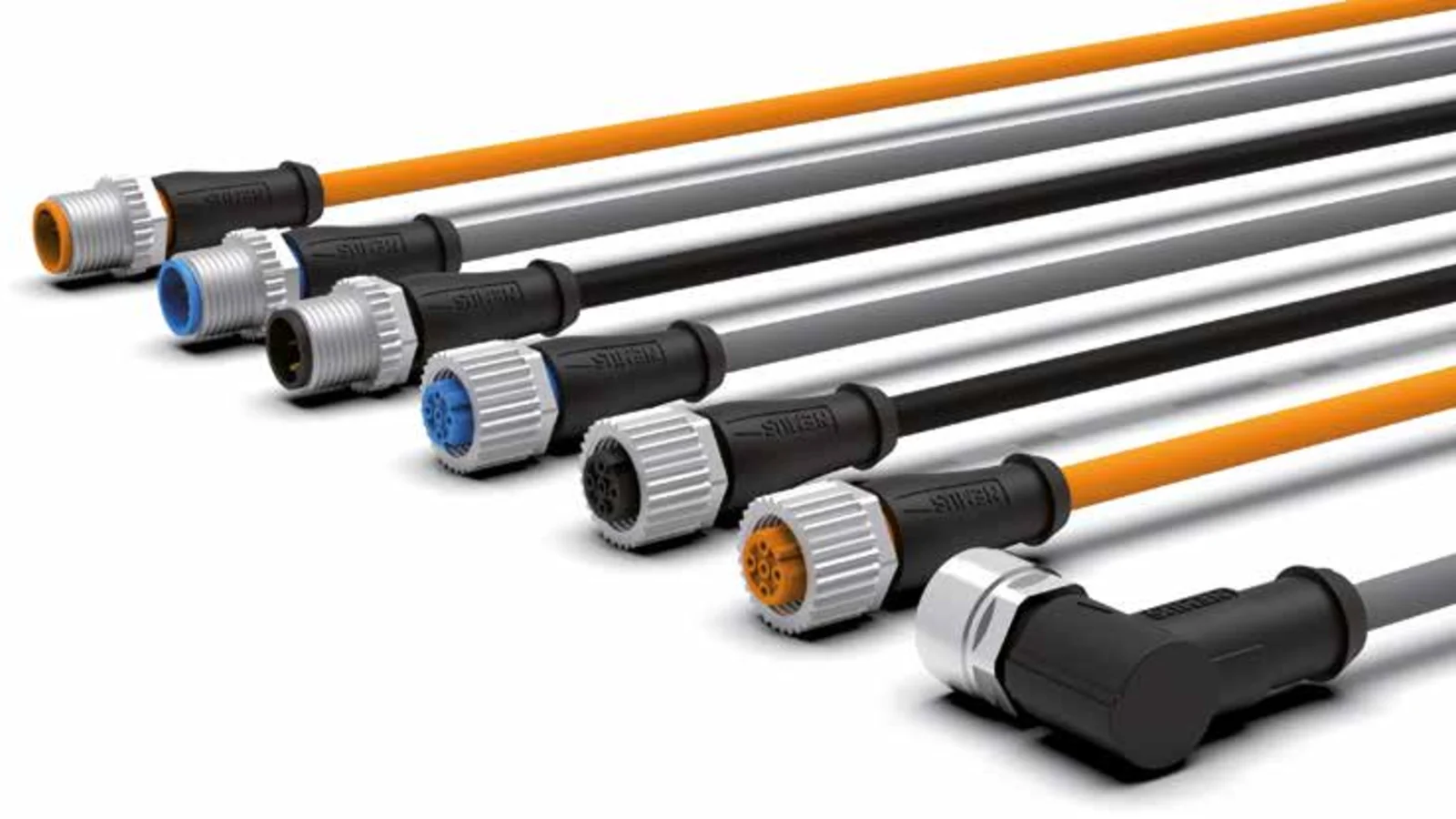
Nemus’ general catalog separates the M12 and M8 product families in dedicated sections for molded cable products. Both families offer various options, including the A-code designation, male and female connection orientations, body shapes with 0° or 90° angles, and cable configurations with either one open end or both ends equipped with connectors. The M12-M8 double-sided connectors are specifically designed for applications where two different mechanical interfaces need to be integrated on the same cable. This indicates that the product cannot be selected solely based on whether it is an M8 or M12 connector; instead, the socket configuration on the device, the pin arrangement, and the interface on the other end of the cable must all be taken into consideration.
The product coding system in the catalog also makes this multi-layered selection process clear. The code includes information such as socket code and diameter, number of contacts, cable characteristics, locking type, cable termination, socket type, color, cable type, and length, all organized in distinct blocks. Therefore, it is not sufficient to determine the order code based solely on the length or type of connector. In particular, two sets of cables that may have the same mechanical appearance could be designated for different applications due to differences in the number of contacts, orientation of the connections, degree of mobility, or the combination of their ends.
When to consider M12 A-coded connectors
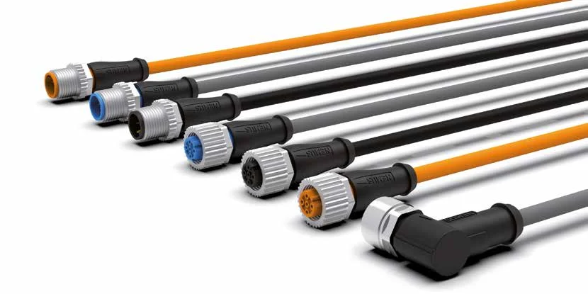
M12 A series products are based on the circular connector design commonly used in automation technologies for connecting sensors and actuators. In Nemus’ catalog, the molded M12 cable sets are available in options with 3, 4, or 5 contacts, as well as in male or female versions with either straight or 90° body configurations. The open-ended types are suitable for applications where the other end of the cable needs to be connected to the appropriate terminal inside the control panel or to the control equipment, depending on the specific requirements of the project. The double-sided types can be used to establish a removable connection between two devices that already have pre-installed sockets.
In the representative technical specifications of M12 A-coded cable products listed in the catalog, the conductor cross-sectional area is specified as 0.34 mm², and the nominal current per contact is 4 A. The maximum operating voltage is indicated as 250 V for four-contact versions and 125 V for five-contact versions; additional limitations may be specified in the product pages or technical tables depending on the specific configuration. It should be noted that these values do not imply that all M12 products have the same capacity under all conditions. When selecting a product, it is essential to verify both the technical specifications of the selected model and the electrical design requirements of the application, taking into account the component with the lowest specified current rating in the circuit.
Applications for M8 A-coded connectors
M8 A series products provide a compact interface in sensor and machine applications where the available space for connections is limited. Nemus’ catalog offers M8 cable-connected connectors with 3 or 4 contacts, available in female or male versions, with 0° or 90° mounting angles, and either single-sided or double-sided configurations. The straight body design allows the cable to extend along the device’s axis, while the 90° body makes it easier to route the cable in spaces where space is limited at the back of the device. However, the orientation of the angled connector must match the natural bending direction of the cable after installation.
In the representative tables for M8 cable-connected products, the conductor cross-section is 0.25 mm²; the maximum voltage ratings for 3- and 4-contact connectors are 50 V AC or 60 V DC; and the nominal current per contact is 4 A. Although the current specifications for M8 and M12 connectors may appear identical in some cases, their voltage ratings, conductor cross-sections, mechanical dimensions, and socket configurations differ. Therefore, classifying M8 connectors as merely “small” and M12 connectors as merely “large” is insufficient for making technical decisions. It is essential to consider the connection scheme and pin functions specified by the device manufacturer; interfaces with the same number of pins but different coding systems or electrical functions should not be used interchangeably.
Straight, 90° and double-ended cable assemblies
Although the orientation of the connector’s outlet may seem like a minor detail, it actually affects the cable’s lifespan and ease of maintenance. Instead of forcing a sharp bend immediately behind the connector, sufficient bending radius should be ensured wherever space permits. If the outlet needs to be placed on the side within a narrow housing, a 90° design can provide a more orderly routing. However, if the angled housing puts the cable in close proximity to moving parts, hot surfaces, or impact zones, a straight-type connector may be more appropriate. It is essential to verify both the CAD layout and the actual mechanical functioning during the testing process.
In options with an open-ended cable, the connector end is manufactured in the factory, while the other end is terminated according to the project requirements. Double-ended cables enable a connection between two pre-existing interfaces, with various combinations of male-female and straight-angle configurations. In the Nemus catalog, these cables are categorized as straight-to-straight, angle-to-angle, or straight-to-angle types. M12-M8 transition cables ensure mechanical compatibility between two interfaces of different diameters; however, it is essential to verify that the electrical functions of the pins correspond correctly. A physically inserted transition cable will not automatically correct any incorrect pin assignments.
Selecting PVC, PVC+ and PUR cables
Nemus’ catalog categorizes cable options based on their application in mobile contexts. PVC is designated for use in stationary environments; PVC+ offers a cost-effective solution for mobile applications; PUR, on the other hand, is considered a high-performance option for both mobile and robotic applications. This classification system requires taking into account the actual movement patterns of the cables, rather than simply relying on their outer sheathing. Even if a cable appears to be stationary, if it moves together with the machine’s cover, is subjected to vibrations, or is constantly bent during maintenance, its path should not be deemed “completely stationary.”
In the comparison table in the catalog, the temperature range for PVC and PVC+ is specified as -15…+80 °C, while for PUR it is -40…+80 °C. For PVC+, a dynamic bending life of 3–5 million cycles is stated under the condition of a bend radius of 10 times the cable outer diameter; for PUR, this value is 4–6 million cycles under the same condition. The maximum accelerations are 10 m/s² for PVC+ and 30 m/s² for PUR, with maximum speeds of 180 m/min and 240 m/min, respectively. These figures should be interpreted in conjunction with the specified bending radius and test conditions in the catalog. In actual applications, factors such as the cycle pattern, stroke length, bending degree, cable carrier type, temperature, as well as exposure to oils and chemicals, can all affect the material’s performance. It is essential to verify the final cable specifications on the corresponding data sheet.
| Selection criterion | Option in the Nemus range | Point to verify in the project |
|---|---|---|
| Connector family | M8 A-coded, M12 A-coded, or M12–M8 | Mating socket, coding, pin count, and pin functions |
| Body direction | 0° flat or 90° angled | Mounting clearance, service access, and the natural direction of cable exit. |
| End arrangement | One-ended or double-ended | Internal panel termination or the connection between two ready-made devices |
| Cable sheath | PVC, PVC+, or PUR | Fixed/movable applications, cycle duration, temperature, and environmental influences |
| Protection | The IP classes specified in the product table. | Ensure that the connection is properly installed, tightened securely, and matched with the correct counterpart component. |
Interpreting IP protection ratings correctly
In Nemus’ standardized M8 and M12 product tables, the IP65, IP66K, and IP67 ratings are specified in accordance with EN 60529, under the condition that the connectors are properly installed and tightened. This requirement should be emphasized prominently in any selection documentation. The IP protection rating does not automatically apply to the exposed ends of cables, the exposed connector surfaces, or connections that have been tightened with insufficient torque. Unused connection points must be protected with appropriate sealing elements; during installation, it is essential to check that the sealing surfaces are free from dirt, damage, or misalignment.
In applications where exposure to washing, heavy dust, splashing, or external environmental factors is present, it is not sufficient to merely check the IP rating of the connector. The counterpart socket, the control panel connection, the cable gland, the exposed end of the cable, and the device’s body all form part of the same protection chain. If the cable’s outer sheath is damaged, the mating surfaces are chemically affected, or the connection is subjected to excessive strain, the system’s performance in the field may be compromised. The level of protection must be assessed based on the completed connection point and the actual installation method used.
Materials, contacts and testing
In the catalog, information on the molded product samples includes details such as CuSn contacts, contact surfaces coated with Ni/Au, nickel-plated zinc casting locking components, TPU bodies, and FKM seals. These catalog specifications indicate that electrical conductivity and environmental resistance were taken into consideration during the design process. However, chemical compatibility should not be inferred solely from the material name; it is essential to obtain current compatibility certifications from the manufacturer regarding the oils, cleaners, or process chemicals that will be used. In particular, applications involving continuous immersion, high-pressure cleaning, or extreme temperature cycles require additional evaluation, as these conditions differ significantly from standard machine operating conditions.
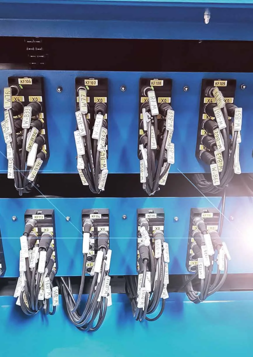
Nemus states in its general catalog that 100% of each connector it produces is tested, including electrical tests, high-voltage tests, performance evaluations, pin-to-pin checks, short-circuit tests, and visual inspections. However, this manufacturing approach does not eliminate the need for ensuring the correct product is used and is properly installed in the field. During commissioning, it is essential to verify the label information, pin assignments, and functional integrity of each cable; cables should not be connected solely based on their color or appearance. Additionally, the entire order code must be recorded in the maintenance inventory.
An important distinction in the scope of UL/CSA claims
On the product pages for wired products in the catalog, terms such as UL AWM and UL 1581 FT-1 are used to indicate certifications and standards. The footnotes on the same pages clearly state that these UL/CSA standards apply specifically to cables. Therefore, the statement “UL/CSA cables are used” does not imply that the entire connector assembly possesses an independent UL/CSA product certification. If a compliance requirement is necessary for a particular project, it is essential to verify, based on the current documentation, which components of the certification are applicable, which order codes are covered, and under what usage conditions the certification applies.
CE and RoHS information should also be obtained from the relevant product page or the compliance documentation. A mark displayed under a product category title should not be automatically applied to all possible combinations of variants. The safest approach is to list the product codes selected during the bidding process and verify the required declarations for each code on the manufacturer’s latest documentation page. This approach not only prevents incorrect generalizations in the technical documentation but also ensures that the right replacement parts are easily identified during maintenance.
Selection steps by application
- Define the interface: Record whether the counterpart socket on the device is of type M8 or M12, the A-code configuration, the male-female orientation, and the number of contacts.
- Verify the functions of each pin. Verify that the power supply connections, signal lines, and any special functions correspond exactly to the device’s schematic diagram.
- Calculate the electrical load: Compare the voltage, continuous current, starting current, and installation standards with the specifications of the selected product code.
- Select the mechanical output option: Select the straight or 90° body type based on the installation space, cable direction, bending radius, and service accessibility requirements.
- Classify the movements: Determine whether the motion is fixed, intermittent, continuous, or robotic in nature; accordingly, select between PVC, PVC+, and PUR materials.
- Assess the environment: Inform the manufacturer separately about the conditions of temperature, oil, chemicals, UV exposure, washing, vibration, and mechanical shocks.
- Clarify the length: Measure the actual cable route, service allowance, and path through the moving cable carrier; avoid unnecessary loops.
- Verify the installation. Include in the installation instructions that the protection class only applies when the connector is properly mated with the corresponding counterpart and securely tightened.
Once these data are available, Nemus industrial connectors can be compared not only based on their appearance but also in terms of their overall functionality for connecting various components. When converting device lists and field conditions into product codes, Oskon takes into account factors such as the connector family, cable configuration, terminal combinations, and environmental requirements. The final decision should be based on the latest information available on the Nemus product page, technical specifications, compliance documentation, and the results of any electrical-mechanical risk assessments conducted for the specific application.