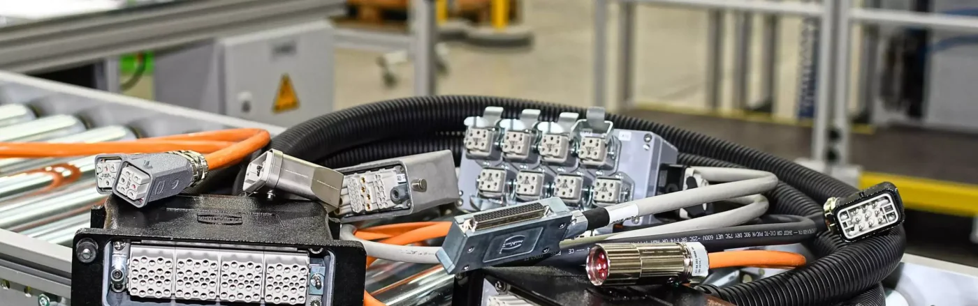
In industrial connection projects, even if the electrical specifications of a standard connector are suitable, the actual implementation may not be possible using off-the-shelf products alone. The mechanical design of the machine, the specific routing of cables, the need to combine different device interfaces into the same cable harness, robot motion requirements, electromagnetic compatibility considerations, the installation sequence, or customer-specific testing documentation may all require a customized solution. HARTING Customised Solutions represents HARTING’s approach to projects that combines its standard connector, cable, and connection technologies with custom-designed cable assemblies, cable harnesses, panel interfaces, and additional mechanical and electronic components tailored to the specific application.
Customization goes beyond simply modifying the cable length of a product listed in a catalog; it represents a more controlled process than designing a completely new, unverified component from scratch. The goal is to utilize HARTING interfaces that are as standardized and well-documented as possible, while addressing any unsolved aspects of the application through engineering efforts. This guide explains how to distinguish between a standard system cable configuration and a truly customized solution, and outlines the steps involved in project initiation, prototyping, and verification. For each project, it is also necessary to verify the feasibility of production, the availability of relevant certifications, the delivery schedule, and the current stock situation.
When is a customised connection solution required?
The first step in the evaluation process is to determine whether the requirement can be met using a standard HARTING system cable. If the appropriate connector family, pin layout, cable type, shielding type, length, and terminal combination are available in the catalog, a standard product is the preferred option – due to its readily available technical documentation, product identification number, and the convenience it offers for reordering. If the system cable configuration can be defined using a configuration tool, this too is usually a structured solution based on existing manufacturing processes. In such cases, each customized product is not necessarily a completely new development.
A custom project becomes necessary when a cable harness with multiple branches, customer-specific pin assignments, special labels and branching points, a machine-specific protective sheath, a custom panel mounting plate, an intermediate PCB, adapters for integrating interfaces from different manufacturers, or a test plan tailored to the specific application are required. According to HARTING’s official website, these solutions can be used in fields such as machinery manufacturing, robotics, and rail systems. They enable the efficient transmission of energy, data, and signals, tailored to the specific application environment. Clearly defining the scope of the project from the outset helps to minimize the number of custom components needed.
The boundary between standard system cabling and custom solutions
| Project situation | The right starting point | Reason for the decision |
|---|---|---|
| The catalog offers options for two types of ends, cable types, and various lengths. | Standard system cable | A selection that can be tracked via the ready-made product number and the published technical data. |
| With existing interfaces, only a configurable length is required. | Configure the system cable. | Within standard production guidelines, the dimensions are customized to fit the specific requirements of the project. |
| Multiple device extensions can be connected from a single main body. | Special cable harness | Application-specific branching, branch lengths, labeling, and mechanical protection |
| The control panel, internal wiring, and field cables all need to be replaced together. | Custom system interface | The connector, circuit board, PCB, and cable assembly must all be verified together. |
| The robot is equipped with specialized motion functions and a set of tools. | Robotic main harness or dresspack | Movement, rotation, arm geometry, and process functions are all designed together. |
| The scope of approval or testing differs from that of the standard product. | Custom development and validation | Technical responsibilities, as well as sample and test documentation, should be established on a project-specific basis. |
Prepare the technical specification before selecting products
The first document detailing a specific connection request includes not only a statement stating “these two devices need to be connected” but also a requirement list that specifies the electrical and mechanical interfaces at both ends. For each circuit, details such as voltage, continuous current, starting or transient current, signal type, communication protocol, as well as the arrangement of protective conductors and screens are provided in writing. The pin assignments are aligned with the current schematic diagrams of the device manufacturer. When power, signal, data, pneumatic, or optical circuits are combined within the same physical connector, their potential interactions and the rules for distinguishing them must be carefully considered.
The mechanical specification must include information such as the outlet direction of the connector, the permitted outer diameter of the cable, the dimensions of the gland or molding area, the total diameter of the cable bundle, the branching distances, and the openings through which the components must be passed during installation. Access for maintenance personnel to the locking elements is ensured, and incorrect connections are prevented through specialized coding systems. The tensile load on the cable and the minimum bending space are controlled by the three-dimensional layout design. HARTING’s engineering services, which include CAD data and product selection tools, are extremely useful at this stage; however, ultimate responsibility for the correct installation still lies with the system designer.
The environmental profile should not be reduced to a single IP classification. Factors such as ambient and surface temperature, oil, cleaning chemicals, UV radiation, ozone, humidity, salt spray, vibration, impact, welding sparks, and cleaning methods constitute separate criteria. For a movable cable, parameters such as stroke, speed, acceleration, number of cycles, bending radius, and bending angle must be specified. The IP rating of a product generally applies when all identical components are properly installed and secured; in addition, the open ends of the cable harness, branching components, and connections to the control panel must also be within the same protective category.
Standard HARTING interfaces as building blocks for custom solutions
In the design of custom connections, the first priority is always to meet the application’s requirements for power, signal transmission, and data communication using HARTING’s existing product portfolio. Han’s industrial connectors, with their various contact and housing options, can be used in machine and control panel interfaces. Circular connectors such as M8, M12, M17, and M23 are ideal for compact field applications, as well as for connecting sensors, actuators, and drives. RJ Industrial, ix Industrial, T1 Industrial, preLink, and fiber optic solutions are ideal for data communication applications. Hybrid interfaces, on the other hand, provide a viable option in cases where multiple types of communication are required to be integrated into a single connection.
In this context, the family name alone does not suffice to demonstrate technical compatibility. For example, the designation “M12” can refer to various types of connectors with different numbers of contacts, as well as those designed for power or data transmission applications; the Han family may include different body sizes, locking mechanisms, monoblock inserts, or Han-Modular components. When customizing a connector, the exact part number, corresponding counterpart, contact configuration, cable cross-section, clamping or termination method, and any additional accessories must be specified on the product data sheet.
Project workflow: from concept to an approved series product
- Application analysis: Devices, signal lists, mechanical layouts, movement patterns, and environmental conditions are all taken into consideration.
- Standard product search: It is checked whether the ready-made system cable or the configurable product meets the required specifications.
- Scope definition: Custom lengths, pinning arrangements, branching patterns, circuit boards, PCBs, protective hoses, and labeling requirements can all be specified.
- Concept and risk assessment: Electrical protection, EMC requirements, mechanical loads, installation procedures, and maintenance methods must all be taken into consideration together.
- Prototype: A representative sample is tested on actual devices, corresponding connectors, and the machine layout.
- Verification: According to the technical specifications, tests such as continuity, high-voltage resistance, functionality, data integrity, shielding, sealing, or environmental testing are conducted.
- Release: The drawing, product BOM, test criteria, as well as label and packaging revisions must be approved by the customer.
- Change management: Subsequent replacements of devices or cables are carried out in accordance with the new revision specifications and, where necessary, involve retesting.
Application example: a pre-assembled interface between a special-purpose machine and control panel
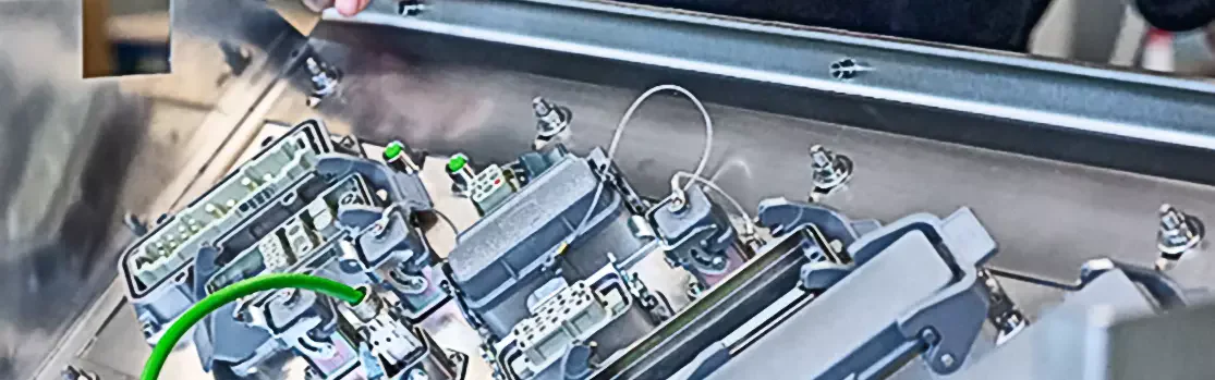
The official case study jointly conducted by HARTING and SUATEC demonstrates why a customized solution can be more comprehensive than using cables of varying lengths separately. In this project, the machine array consisted of 50 individual cables, each containing between 4 and 25 conductors. In a traditional setup, these conductors would need to be prepared on-site and connected individually to the control panel. The proposed solution incorporated pre-assembled cable arrays, industrial connectors, a stainless steel mounting plate, and a specialized PCB designed for use within the control panel.
According to the official case study, a custom PCB took over the function of the terminal block, which contained 200 low-voltage contacts; ready-made adapters were directly connected to HARTING industrial connectors. The project involved various steps, including preliminary discussions, clarification of technical requirements, concept development, sample production, prototype testing, electrical testing, and EMC testing. The reported reduction in assembly time by at least 30% is specific to this customer’s previous methodology and project scope, and should not be used as a guarantee of similar performance or time savings for other machines.
Main harnesses, dresspacks and floor cables in robotic connections
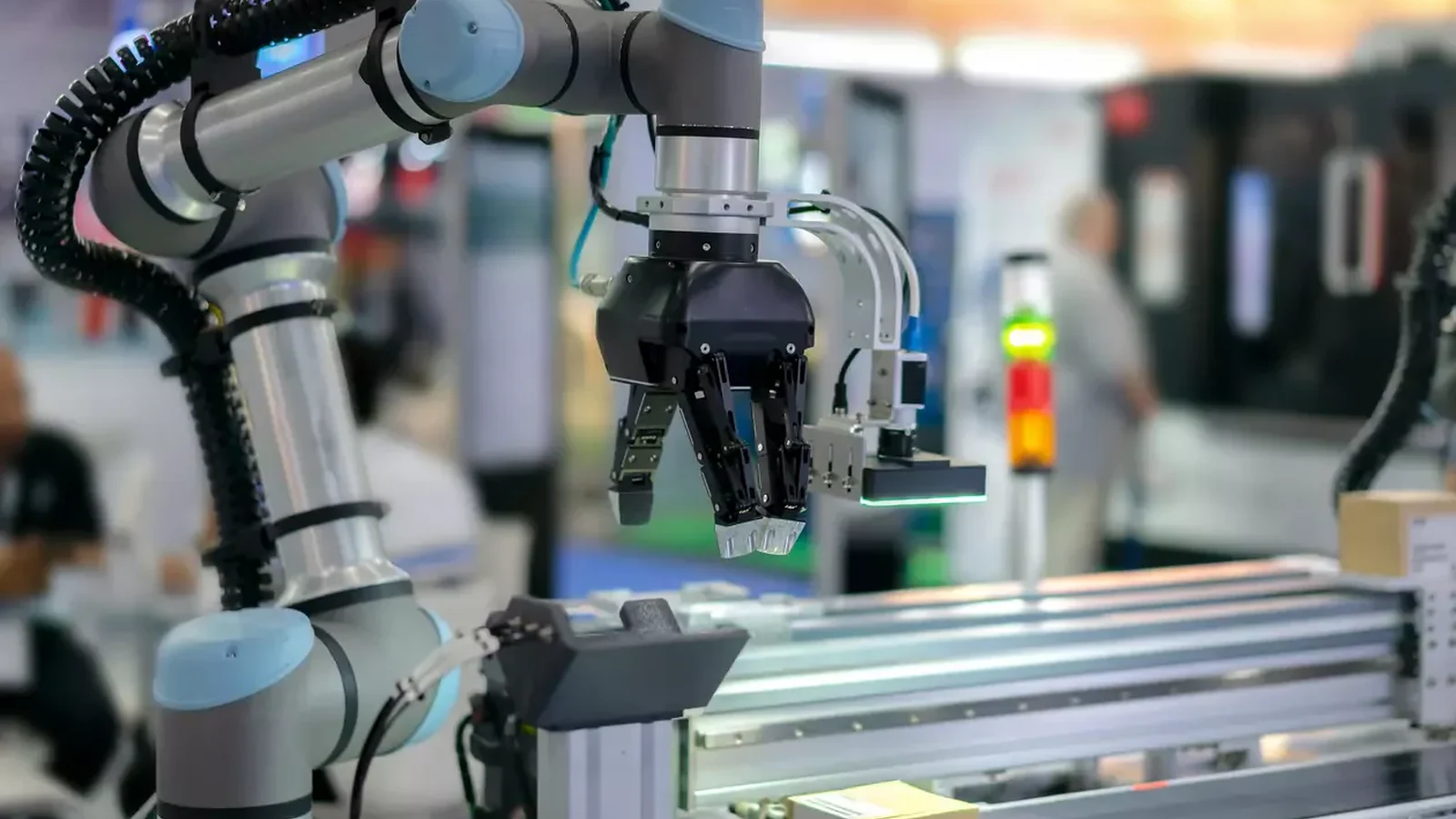
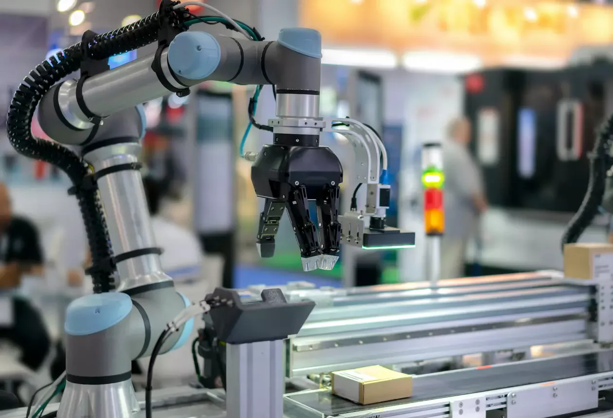
Due to the different movement areas, a robot’s wiring does not consist of a single type of cable. HARTING Customised Solutions’ robotics page describes the main cable harness as an internal wiring solution that extends from the robot base to the motors, actuators, or sensors along its axis. The external wiring, known as “Dresspack,” is designed according to the robot’s specific process tasks, such as welding, material handling, or painting. The “floor cable” serves as a ready-made connection that transmits power and control signals between the control panel and the robot base.
This distinction clarifies the motion profile, service method, and replacement module. An internal robot main harness and an external dresspack removed during tool changes experience different bending, torsion, and chemical exposure. Cable type, protective tubing, clamp spacing, bending allowance, and connector positions must be designed for each assembly. The aim is to transmit power and data reliably while clearing the robot’s movements and allowing practical maintenance replacement.
Interface matching in decentralised power distribution
HARTING’s publication regarding PULS and FIEPOS demonstrates how existing standard interfaces can be integrated into a customer-specific system. The official document specifies that for AC power inputs, FIEPOS variants such as Han Q4/2, Han Q5/0, M12 S-coded, and 7/8-inch cable connectors are used; for DC power outputs, Han Q4/0, Han Q2/0, M12 L-coded, and various 7/8-inch solutions are applicable. For signal transmission, communication, and status monitoring, M12 A-coded cable connectors are utilized.
This list does not constitute a comprehensive power distribution “recipe”; it merely includes examples of interface components in the context of collaborative development. The same coding standards or product families should not be directly applied to other circuits, currents, or devices. The project addressed single-phase and three-phase AC inputs, DC outputs, and signal connections as separate functional components, and utilized prefabricated, tested cables to support a decentralized power distribution architecture. For similar applications, it is essential to first verify the interface specifications of the device to be connected and the current product configuration.
What should the validation plan cover?
The acceptance criteria for special products are defined during the bidding phase. For each cable assembly, parameters such as pin-to-pin continuity, short-circuit testing, conductor resistance, protective conductor continuity, and high-voltage testing (if required) can be specified. For Ethernet or other data lines, not only continuity testing but also transmission tests that comply with the target category and channel structure are necessary. In the case of shielded motor cables, the 360-degree shielding of the wires, as well as the EMC pathways and grounding systems between the cable body and the control panel, must be thoroughly inspected across the entire system.
HARTING’s drive cable product page indicates that IP protection, current-carrying capacity, vibration resistance, as well as data and signal quality tests can be conducted in accordance with customer specifications. However, the specific scope of these tests varies depending on the project. The IP test should simulate the condition of matched components being securely connected; the durability test should reflect the actual bending and torsion patterns; and the temperature test should represent the most extreme installation conditions possible. The sample used in the acceptance report, the revision version, the testing method, and the resulting test data must all be traceable.
Series production and lifecycle management
Just as important as the technical success of a customized solution is its ability to be reproduced. The approved bill of materials specifies connectors, contacts, cables, accessories, protective components, labels, and packaging in detail, including complete part numbers. The cable cutting length, stripping dimensions, crimping tools, and quality criteria are all defined in the controlled production instructions. In cases of machine variations, bundles that may appear similar but have different pin configurations must be distinguished through color, coding systems, mechanical markings, or clear labels.
Life cycle planning: This includes estimating annual production volumes, determining batch sizes, assessing the need for spare parts, revising the product structure, and establishing the approval process for any component changes. Stock levels or delivery times cannot be disregarded in this process; current production and supply conditions must also be verified in the project proposal. When a device manufacturer modifies the function of a connector or pin, merely updating the drawings is insufficient—it is necessary to evaluate the resulting electrical risks, ensure compatibility with existing components, and conduct retesting.
Documentation to prepare for a quotation
- Manufacturer, model, and current interface documentation of the devices to be connected
- Gender, coding, contact count, pin assignment, and locking mechanism for each connector
- Voltage, continuous and peak current, signal or data protocol, and shielding requirements
- Precise drawing of the main route, arm lengths, tolerances, service margins, and branching points.
- Required travel, speed, acceleration, radius, and cycles for fixed installation, cable carrier, torsional, or robotic motion
- Requirements regarding temperature, oil, chemicals, UV radiation, water, dust, vibration, impact, and fire resistance.
- The scope of items including the control panel, cable glands, PCBs, adapters, protective hoses, and mounting components.
- Label content, serial number, traceability, packaging, and management of machine variants.
- The required standards, market approvals, testing methods, number of samples, and acceptance criteria.
- Responsibilities for prototype development, pilot production, mass production, spare parts supply, and revision approvals.
Once this document is completed, the customization process transforms what was initially a vague request for a “special cable” into a well-defined engineering project. Oskon is able to retain those aspects where standard HARTING system cables are sufficient, while designing only the necessary components using HARTING Customised Solutions. In this way, electrical compatibility, installation time, maintenance requirements, quality, and the entire life cycle of the product are all assessed within the same technical framework.