When choosing a coaxial cable, the question “RG6 or RG11?” is just the beginning—not a complete description of the product. The specifications vary depending on the material of the core conductor, the foam insulation, the materials used for the shielding layers, the shielding class, the outer sheath, the impedance, the return loss, the frequency-dependent attenuation, and the CPR class. Birtaş Kablo’s current coaxial cable portfolio offers various options within the RG6/U and RG11/U families, including Cu/Cu, Cu/Al, PVC, PE, and HFFR materials, as well as different levels of shielding and EuroClass certification. This guide explains which additional parameters should be compared beyond the product name in order to select the right coaxial cable for broadcasting and surveillance applications.
The current coaxial cable range
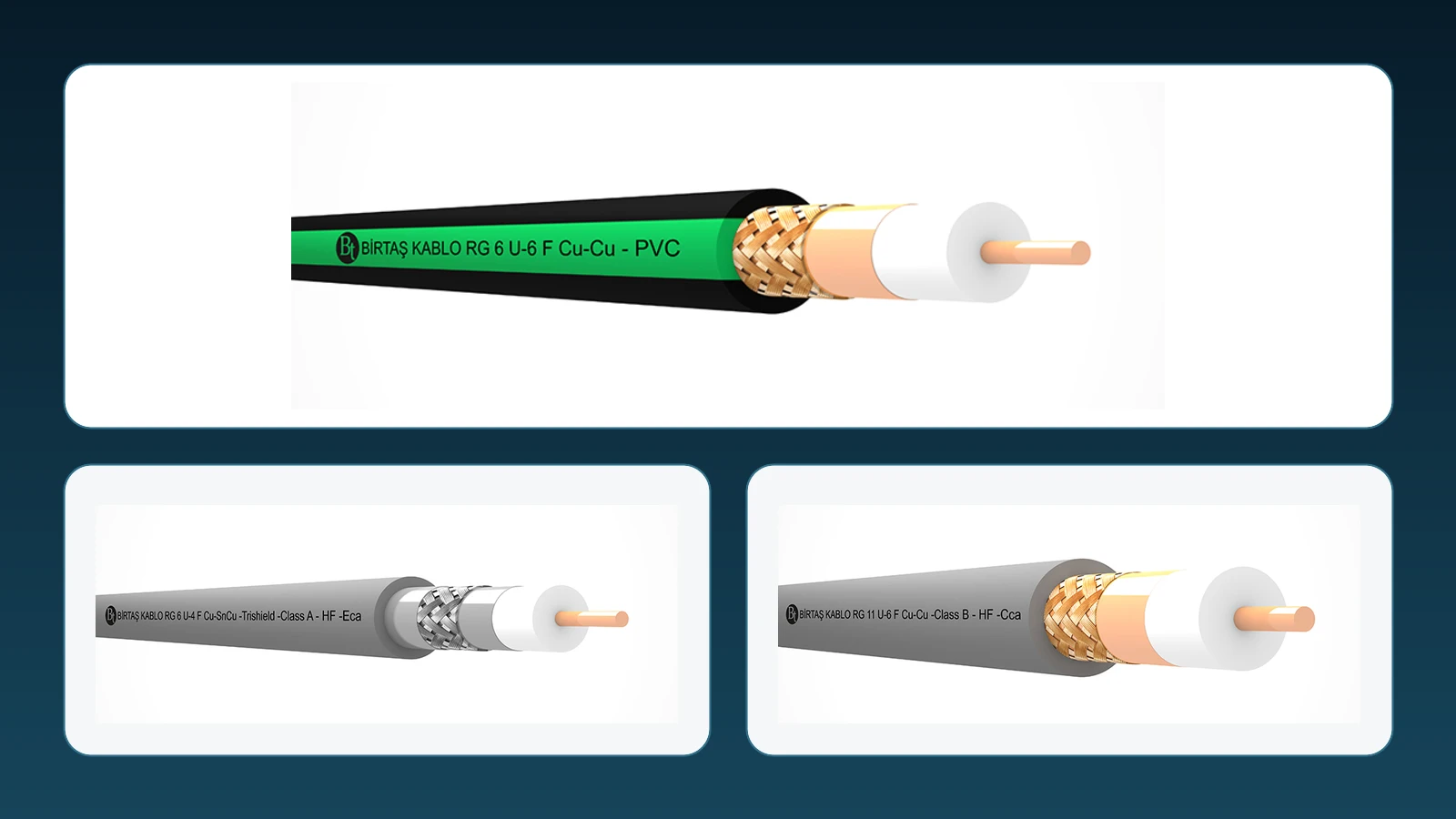
On the official product category page, you can find RG6/U-6 F and RG11/U-6 F types with PVC sheaths; four-layer options using aluminum foil and Cu/Al composite materials; RG6 and RG11 versions with PE sheaths; HFFR-made RG6 and RG11 types; as well as variants classified as Class A or Class B in terms of shielding, and designated as Eca or Cca. The fact that different materials and performance characteristics exist under the same names RG6 or RG11 indicates that it is not appropriate to use only the general description “RG” in the specifications.
The manufacturer’s category description associates coaxial cables with applications in television, camera systems, broadband, and precision signal transmission. However, the selected product pages that provide numerical specifications specifically mention 75 Ω CATV, SMATV, and MATV cables for indoor wiring and distribution purposes. It should not be assumed that these cables are suitable for other protocols or RF applications; instead, the entire cable range must be carefully compared against the system manufacturer’s specified requirements regarding impedance, frequency range, and connector types.
Why coaxial geometry matters
In a coaxial structure, the central conductor is surrounded by dielectric insulation, shielding layers, and an outer sheath, all wrapped around the same axis. The geometry between the signal conductor and the shielding layers is fundamental to determining the characteristic impedance and high-frequency performance of the cable. This geometry can be altered if the cable is compressed, bent excessively, or connected using inappropriate connectors. Therefore, the value of 75 ± 3 Ω specified in the catalog is not merely a property of the raw material; it represents a critical parameter of the transmission line that must be maintained through proper manufacturing and installation processes.
If the impedance matching is disrupted in the system’s components such as sources, cables, splitters, connectors, and termination devices, a portion of the signal will be reflected back. Return loss is one of the indicators that measure this impedance matching as a function of frequency. A higher dB value indicates lower reflection; however, this value is specified using different limits for different frequency ranges. Evaluating a cable solely based on its “75 ohm” rating fails to take into account the impact of attenuation and return loss within its operating frequency range.
RG6/U-6 F Cu/Cu PVC: a basic indoor variant
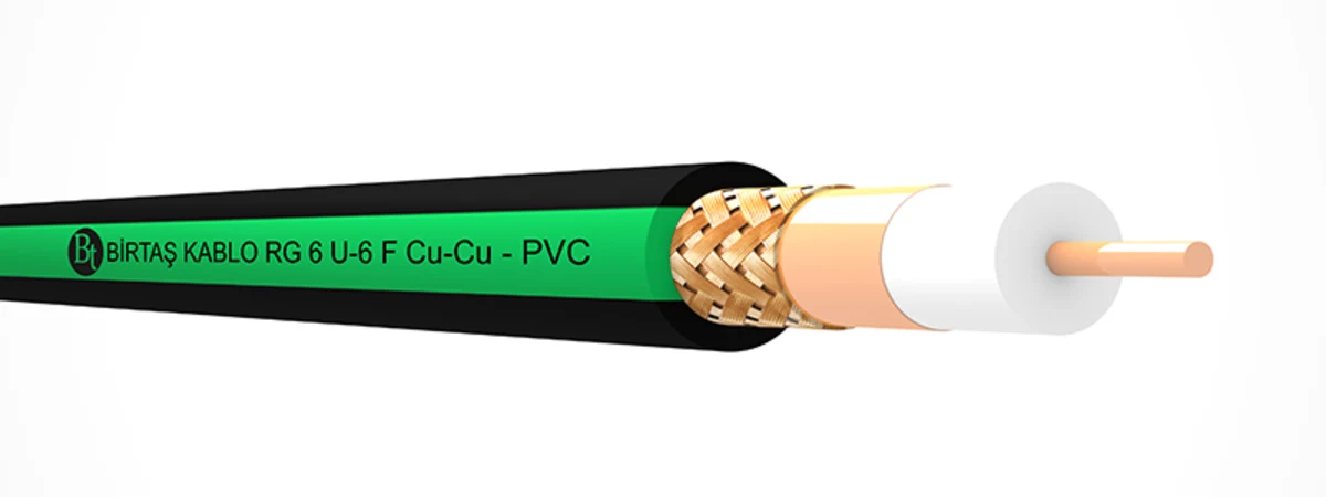
On the product page for RG6/U-6 F (Cu/Cu) / PVC cables, the central conductor has a diameter of approximately 1.02 mm and is made of pure copper. The physically foamed PE insulation has a diameter of approximately 4.60 mm and is covered by Cu-PET tape with 100% coverage and a bare copper braid. The PVC outer sheath, in accordance with EN 50290-2-22/TM51 standards, has a diameter of around 6.80 mm. The product code is 1301 06 006 004, and the approximate weight of the cable is 46 kg/km. This configuration illustrates how the specifications “Cu/Cu” are specifically implemented in terms of the central conductor and shielding components of this cable.
The selected variant is defined in accordance with the EN 50117-9-2 standard; its typical capacitance is 52 ± 2 nF/km, the impedance is 75 ± 3 Ω, and the propagation speed is approximately 82%. The minimum insulation resistance is specified as 2000 MΩ·km, and the minimum bending radius is 10 x D. The official application scope includes indoor CATV, SMATV, MATV systems, as well as the distribution of interactive services; it does not cover outdoor applications or direct burial in the ground. The green stripe on the black sheath should not be interpreted as evidence of outdoor suitability or CPR classification.
RG6/U-4 F HF Trishield: a Class A option with three shielding layers
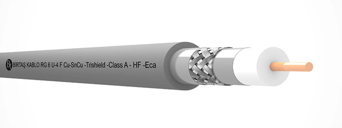
The RG6/U-4 F HF Trishield (Cu/SnCu) / Class A / EuroClass Eca product under examination contains a solid bare copper conductor with a diameter of approximately 1.02 mm, as well as a PE insulation layer made of physical foam with a diameter of approximately 4.60 mm. The shielding structure consists of a 100%-coverage aluminum polyester tape, a tinned copper braid, and another 100%-coverage aluminum polyester tape. The outer sheath is made of HFFR material, with a outer diameter of approximately 6.80 mm, and complies with the EN 50290-2-27 standard. The official product page specifies that this exact variant meets the EN 50117-9-2 standard, has a Class A shielding rating, and its CPR properties comply with the EN 50575 specification, with the Euroclass Eca classification.
In this variant, the transfer impedance in the range of 5–30 MHz is specified at a maximum of 5 mΩ/m, both on the official product page and in the accompanying technical data sheet. However, the shielding performance and return loss values in the HTML product page and the downloadable PDF file differ: the page indicates values of 85/75/65 dB for shielding attenuation, while the PDF shows 75/65/55 dB. Therefore, before specifying exact frequency band limits in the design and approval documents, it is necessary to obtain confirmation from the manufacturer regarding the current revision standards. The Class A, 75 ± 3 Ω, and Eca specifications are consistent in both official documents. If the connector and additional components do not support the same shielding performance, the cable’s classification alone cannot guarantee the system’s overall performance.
RG11/U-6 F HF Cu/Cu: an option to assess for lower attenuation
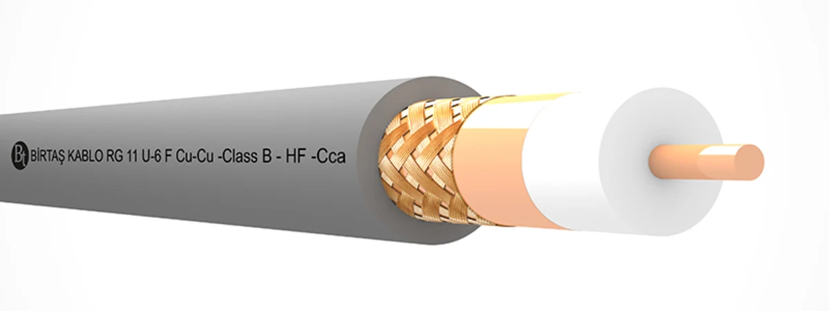
The product page for RG11/U-6 F HF (Cu/Cu) / Class B / EuroClass Cca specifies that it consists of a solid bare copper conductor approximately 1.63 mm in diameter, physically foamed PE insulation approximately 7.15 mm in diameter, Cu-PET tape with 100% coverage, and a bare copper braid. The HFFR outer sheath has a outer diameter of approximately 9.80 mm. The product code is 1305 04 011 702, and its approximate weight is 98 kg/km. The same page clearly indicates that the shielding class is Class B, the transfer impedance at 5–30 MHz ranges up to 15 mΩ/m, and the CPR compliance meets the EN 50575 Class Cca standard.
The attenuation table for this specific RG11 variant indicates that at 20 °C and 5 MHz, the maximum loss is 1.80 dB/100 m; at 1000 MHz, it is 15.30 dB/100 m; at 2150 MHz, 23.00 dB/100 m; and at 3000 MHz, 29.90 dB/100 m. For the RG6 Trishield Eca variant under consideration, the corresponding values at these frequencies are 2.80 dB/100 m, 22.00 dB/100 m, 32.50 dB/100 m, and 39.30 dB/100 m, respectively. This comparison demonstrates why the RG11 variant may be a viable choice for longer distribution lines; however, factors such as the shielding class, sheath material, CPR rating, cable diameter, and connector compatibility must also be taken into account when making a decision.
Comparison of selected variants
| Technical criterion | RG6 Cu/Cu PVC | RG6 HF Trishield | RG11 HF Cu/Cu Cca |
|---|---|---|---|
| Central conductor | Solid bare copper, approximately 1.02 mm in diameter | Solid bare copper, approximately 1.02 mm in diameter | Solid bare copper, approximately 1.63 mm in diameter |
| Approximate outer diameter | 6.80 mm, PVC | 6.80 mm, HFFR | 9.80 mm, HFFR |
| Screen structure | Cu-PET + bare copper mesh | Al-PET + tinned copper braid + Al-PET | Cu-PET + bare copper mesh |
| Shielding class | The class is not specified on the page being reviewed. | Class A | Class B |
| CPR / EN 50575 | The EuroClass specification is not mentioned on the page being reviewed. | Eca | Cca |
| Impedance | 75 ± 3 Ω | 75 ± 3 Ω | 75 ± 3 Ω |
| Minimum bending. | 10 x D | 10 x D | 10 x D |
How to calculate the attenuation budget
Cable loss is calculated by applying the dB/100 m value listed in the manufacturer’s table to the actual length of the cable. This calculation takes into account passive components such as tap-off devices, sockets, connectors, and splices. The output level of active devices, the total loss of the cable at its highest operating frequency, and the receiver’s acceptance range are also evaluated using the same table. If the line is only intended to operate up to 1000 MHz, the 3000 MHz figure does not directly apply as a design parameter; however, if future bandwidth expansion is planned, the high-frequency performance becomes an important consideration in the selection process.
The catalog attenuation is typically specified at the defined temperature and using a standard sample. In the field, factors such as temperature, differences in reel quality, connector manufacturing defects, and cable compression can affect this value. Therefore, it is necessary to include an appropriate allowance within the design budget and record the measured levels and quality parameters during commissioning. Using RG11 for long-distance applications can reduce losses; however, it requires a larger outer diameter, a larger bending radius, and different connectors. These mechanical considerations must be taken into account alongside the electrical performance benefits.
Shielding class and number of shielding layers are different
The presence of two or three shielding layers in a cable is a matter of structural design; the classification of a cable as Class A, Class B, or another category is determined by the transfer impedance and the shielding attenuation measured within specific frequency ranges. Even if two products have similar cross-sectional configurations, the density of the shielding material, the type of foil used, and the actual measurement results can vary. Therefore, the phrase “double-shielded” alone is not sufficient in a purchase specification. The required shielding class, the applicable standard, and the specific frequency ranges must be clearly stated in the product documentation.
The weakest link in an application is often the termination. Cutting off a large portion of the wire, failing the foil to continue along the connector, loose connections, or mismatches in the impedance and shielding continuity of connectors designed for different diameters can all cause problems. The connector body, the crimp dimensions, the separator, and the end plug are all integral components of the same system. If the shielding quality is only guaranteed for the wire coming out of the reel, it cannot be assumed that the installed system will also maintain the same level of protection.
Selecting PVC, PE and HFFR sheaths
The options of PVC, PE, and HFFR serve the same purpose, but they cannot automatically replace each other. The product pages for PVC and HFFR products specify their use for indoor applications only, excluding outdoor use or direct burial in soil. The presence of RG6 and RG11 types with PE coatings in this category does not imply that all PE products are suitable for direct burial, submersed use, or exposure to all types of outdoor environments. Information regarding UV resistance, moisture absorption, water ingress, temperature tolerance, and suitability for different installation methods must also be confirmed on the technical specifications of each specific PE variant.
For HFFR products, the tests regarding non-halogen content, smoke density, and flame retardancy are clearly listed on the product pages. However, the CPR performance is categorized under a separate heading. For example, the RG6 Trishield variant discussed here is designated as Eca, while the RG11 variant is designated as Cca. The term “HFFR” alone does not imply Cca; it cannot be assumed that a product labeled Cca also belongs to the RG11 category. The CPR requirements of a particular project must be carefully matched with the exact product code and its corresponding performance specifications.
Installation, labelling and acceptance tests
When installing coaxial cables, it is essential to comply with the manufacturer’s specified minimum bending radius. The arrangement of the reels and trays must be such that they do not compress the cable. The pulling force should not be applied uncontrolledly to the outer sheath or the braiding. It is important to maintain a clear separation in the routing between power cables and equipment that generates high electromagnetic fields. At both ends, the cable should be labeled with its corresponding outlet port and target plug type. For RG6 and RG11 cables, connectors of the correct size must be used, and the length of the central conductor, as well as the process of folding and clamping the braiding, must be carried out in accordance with the manufacturer’s instructions.
In acceptance inspections, merely conducting continuity tests is not sufficient. Measurements must be taken within the operating range of the installed system to verify parameters such as level, return loss, and compliance with relevant broadcasting standards. During visual inspections, factors such as severe bending, crushing, sheath damage, exposed shield wires, and loose connectors are checked. For projects requiring fire-resistant performance, the delivered reel label, product code, CPR performance declaration, and technical documentation are compared against each other. The Cca or Eca classification is not a result obtained through on-site retesting with a testing device; rather, it represents a class that has been verified through the correct product and documentation chain.
Oskon's approach to coaxial infrastructure
Oskon does not select cables independently of the devices in camera and broadcasting infrastructure. The link budget is determined based on factors such as the frequency range, distribution topology, the longest line length, losses in passive components, and the receiver’s signal range. When comparing RG6 and RG11 cables, one should consider not only the cost per meter but also differences in attenuation, outer diameter, cable-tray fill, bending radius, and connector standards. In environments with high electromagnetic interference, the required level of shielding must be specified as a project requirement.
In the application package, the cable list, one-line diagram, port numbers, passive component values, route details, and test forms are all included together. In the event of a request for modifications, the product’s 75 Ω impedance, operating frequency range, return loss, shielding class, sheath material, and CPR specifications are rechecked. This ensures that no variant with different performance characteristics is deployed under the same model name, and it also helps to establish clear and measurable acceptance criteria for the installed system.
Checklist before purchasing
- Is it a 75-ohm system, and what is the actual operating frequency range?
- Have the losses due to long cable lengths, splitters, sockets, and connectors been included in the link budget?
- Does the choice between RG6 and RG11 depend on the attenuation table of the specific variant being used?
- Are the materials for the central conductor and shield clearly specified as Cu/Cu, Cu/Al, or otherwise?
- Has the required shielding class and frequency range been confirmed in the product data sheet?
- Are PVC, PE, or HFFR coatings suitable for actual installation environments?
- Does the CPR class match the declaration of performance for the exact product code?
- Have the connector and mounting equipment been selected according to the outer diameter of the cable and the system specifications?
- Have the level requirements, return loss specifications, and visual acceptance criteria been defined for the installed line?
Frequently asked questions
Is RG11 always better than RG6?
No. The attenuation of the RG11 variant under consideration is lower than that of the selected RG6 variant; however, the RG11 cable is thicker and heavier, and its mounting requirements and connectors differ from those of the RG6 cable. For short distances, RG6 may be more suitable. The decision regarding which type of cable to use should be based on factors such as the operating frequency, the distance, and the total system losses.
Does Trishield automatically mean Class A?
It is not possible to make a generalization. The RG6 HFFR Trishield product page specifically indicates a Class A rating. The class of any other Trishield product must be verified according to its own technical documentation.
Is an HFFR cable automatically Cca-rated?
No. The HFFR RG6 product under consideration was published under the name “Eca,” while the HFFR RG11 product was published under the name “Cca.” The term “HFFR material” and “CPR EuroClass” refer to different information.
Official Birtaş Kablo resources
- Current Category Page for Coaxial Cables
- RG6/U-6 F (Cu/Cu) / PVC Product and Technical Information Page
- RG6/U-6 F (Cu/Cu) / PVC official technical specification
- RG6/U-4 F HF Trishield Class A EuroClass Eca product page
- RG6/U-4 F HF Trishield Class A EuroClass Eca official technical specification
- RG11/U-6 F HF Cu/Cu Class B EuroClass Cca product page
- RG11 HF Class B EuroClass Cca official data sheet