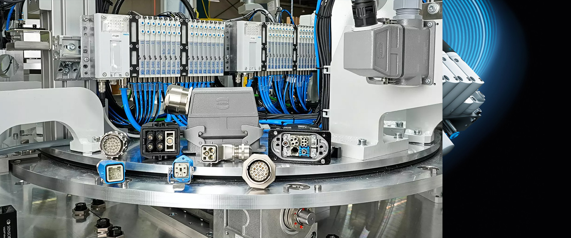
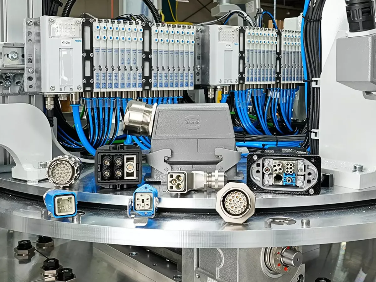
An industrial connector not only electrically connects two parts of a machine but also serves as a reliable separation point during installation, commissioning, maintenance, and module replacement. The rectangular connectors in HARTING Han’s portfolio can be used to integrate power, control signals, industrial data, and, in suitable Han-Modular configurations, compressed air lines in a single interface. However, the term “Han connector” by itself does not refer to a complete product; its use requires the selection of a suitable housing or cover, male and female inserts, a modular frame, appropriate contacts, cable entries, locking mechanisms, and any additional accessories needed for the specific application.
This catalog and selection guide are designed to help match HARTING Han industrial connector options with specific project requirements. First, it is necessary to determine the amount of energy and signals to be transmitted, the cable configuration, the environmental conditions, the mechanical installation requirements, and the maintenance considerations. Subsequently, the body size, inserts, contacts, termination methods, and accessories must be verified based on the product code. The current values for current, voltage, cross-section, protection class, and temperature mentioned in this document apply only to the example specified by its name and product number; they cannot be automatically applied to other variants within the same family. For a final decision, it is essential to refer to the latest HARTING technical data sheets, installation instructions, and relevant industry standards for the particular project.
Treat the Han connector as a component system
The fixed side of a rectangular industrial connector can be connected to the machine body, the control panel, or another cable; the movable side can be equipped with a flat or angled cover, depending on the cable outlet direction. HARTING’s product range includes various mechanical configurations such as panel-mounted bodies, cable-to-cable connectors, bulkhead-mounted types, covers, and panel-mounted interfaces. Designations like “3A”, “6B”, or “10B” refer to the physical dimensions of the connector and the compatible mounting areas; these codes do not indicate the connector’s current-carrying capacity or voltage rating. The electrical specifications are determined by the selected inserts or modules, as well as the contact design, conductor material, and operating conditions.
On the completed product tree, the matching male and female components, the gender of the contacts, the orientation of the module or insert, and the type of locking mechanism must be clearly indicated. The cable gland or other cable entry device is selected based on the cable’s outer diameter, the requirement for sealing, the pulling load, and, where applicable, the continuity of the electromagnetic shielding. Accessories such as blind caps, coding elements, protective covers, and gaskets should be added to the list according to the specific application scenario. It should not be assumed that components that appear next to each other in the catalog are compatible; the combination must be verified using the HARTING Han Configurator and the technical specifications of each individual component.
Monoblock inserts or Han-Modular configurations?
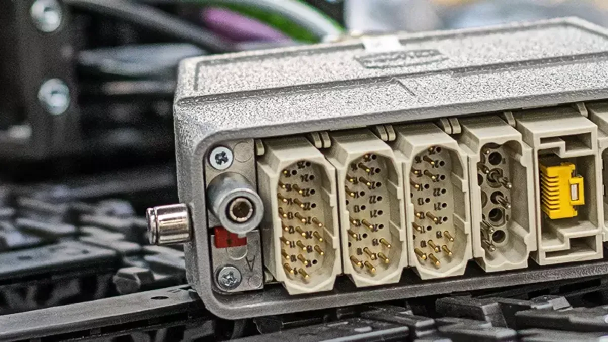
In applications where a uniform type of contacts and a fixed number of poles are sufficient, the monoblock insert can represent a solution that is straightforward and easy to manage. The number of poles of the insert is compared with the requirements specified in the circuit diagram regarding contact current, voltage, conductor cross-section, and termination technology. The Han-Modular series may be an appropriate choice when it is not necessary to separate power, control, and data circuits into separate connectors, or when different connection scenarios need to be integrated within the same mechanical interface. Its modular design allows different functional modules to be installed within a standard industrial housing.
The Han-Modular portfolio includes not only electrical power and signal contacts but also suitable data and pneumatic modules. However, this flexibility does not mean that each module can be installed in any frame or adjacent arrangement without restrictions. The number of module slots, frame type, male/female connector compatibility, permitted operating parameters, cable outlet dimensions, insulation distances, and possible shielding configurations must all be carefully controlled at the design stage. If different voltage classes are present within the same housing, appropriate insulation coordination and application standards must also be taken into account.
Examples on the official product pages show why module specifications must be checked by product code. The male crimp Han DDD module, product number 09 14 017 3001, has 17 contacts, a 0.14–2.5 mm² conductor range, and a 10 A nominal current. Product number 09 14 002 3042, Han 70A crimping module, 1500V male connector , has two contacts, a 6–25 mm² conductor range, and a 70 A rating. Product number 09 14 004 3041, Han CC Protected Module , has four contacts, a 1.5–6 mm² range, and a 40 A rating. Product number 09 14 006 3001, the male Han E module has six contacts, a 0.14–4 mm² conductor range, and a 16 A rating. These values apply only to the specified product numbers; check temperature, adjacent module loading, and derating conditions in the current data sheet.
Han-Eco: define the limits of plastic housing selection correctly
Han-Eco is the product family used by HARTING for the manufacture of industrial connector bodies made from high-performance plastics. Compared to metal bodies, their lower weight and non-conductive material can offer advantages in certain machine and control panel designs. The portfolio includes various variants that can be used with both monoblock and modular inserts. However, the use of plastic bodies is not always a universal solution that eliminates the need for protective grounding or shielding measures. The configuration of the circuits carried by these plastic connectors, as well as the continuity of metal cable shielding and the design of equipotential connections, must be determined on a case-by-case basis.
The level of protection cannot be determined merely by the name “Han-Eco.” It is essential that the cover/body, seals, cable entries, blind caps, locking mechanisms, and all accompanying components be properly installed; an open or unmated connector cannot provide the same level of protection. The effects of chemicals, oils, UV radiation, the external environment, mechanical stress, and temperature must be considered in conjunction with the material properties and environmental factors of the selected product. When deciding between a plastic or metal body, one should consider not only the purchase price but also factors such as weight, corrosion resistance, EMC compliance, earthing capabilities, maintenance requirements, and environmental durability.
Match termination technology to the production process
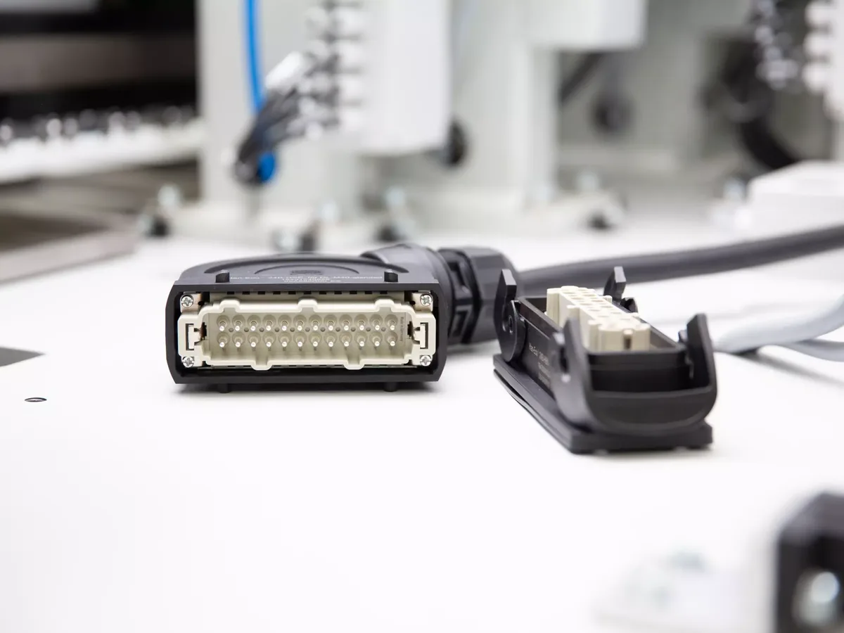
HARTING Han’s portfolio includes various termination technologies such as crimping, screwing, Push-In, Han-Quick Lock, IDC, cage-clamp, Fast, and preLink. It should be noted that not all of these methods are available for every type of connector or module. The selection of a termination method should take into account factors such as the cable’s solid or stranded conductor construction, conductor cross-section, ferrule use, number of installations required, field accessibility, vibration conditions, and quality assurance requirements. While it is important that maintenance personnel are familiar with a particular method, familiarity alone does not suffice to ensure technical compatibility.
Crimping connections aim to create a controlled, gas-tight deformation between the contact and the conductor. HARTING refers to the requirements of IEC 60352-2 for crimping processes. To achieve the desired results, the selected contact type, the permitted conductor cross-section and structure, the stripping length, the crimping die, and the settings of the crimping tool must all form part of a unified process recipe. The crimp height, the pull-test results, and visual inspections must also be verified in accordance with the quality specifications. Failing to use the appropriate die or mixing contacts from different families can result in a connection that appears solid on the outside but is actually unreliable.
In push-in connections, the prepared conductor can be directly inserted into the spring-loaded connection point; the type of conductor and its preparation method must match the product specifications. Screw connections may be suitable for use with common tools in the field, but they require the correct terminal configuration and the specified torque. Methods such as IDC and Han-Quick Lock utilize different mechanical principles to simplify conductor preparation. preLink, on the other hand, is designed to enable the use of pre-ended connection components in various applications for data cabling. For each of these methods, operator training, initial component inspection, and proper disassembly/reassembly procedures must be established.
Housing, locking and environmental protection
The material of the cover and body, the surface coating, and the locking mechanism determine the mechanical performance of the connector. Options such as single or double latches, threaded locks, or other custom solutions are selected based on considerations of vibration resistance, accessibility, and the need for enhanced safety against unintended opening. Whether the cable outlets are located at the top or the side affects the bending radius required when installing the device on a machine, as well as the maintenance procedures. The panel layout, mounting holes, gasket surfaces, and clamping torque must all be carefully designed according to three-dimensional dimensioning requirements.
Product number 09 40 010 0391, Han 10 HPR HBM – Rear-fit version is a recent example that illustrates why specific values depend on the product code. HARTING describes this rear-mounted 10B bulkhead body as featuring threaded locking, corrosion-resistant powder-coated aluminum casting, and an NBR seal. The product page specifies the applicable temperature range as −40 °C to +125 °C in accordance with IEC 61984, as well as a tightening torque of 3 Nm for the fixing screws and 4 Nm for the threaded lock. Information on IP65, IP68, IP69, IPX9K, and UL Type 4/4X/12 is also provided on the same page. These values should only be considered in the context of this specific body being installed in accordance with the instructions and secured with the appropriate accessories; they do not represent common characteristics of all Han or HPR products.
| Application question | Han solution to consider | Data to verify against the product code in the quotation |
|---|---|---|
| Fixed-pole number: for power connection or control connection? | Appropriate monoblock Han inserts and matching covers/bodies. | Number of contacts, current, voltage, conductor cross-section, termination type, and body dimensions |
| Are power, signals, data, or pneumatic signals all transmitted through the same interface? | Han-Modular frames and task-specific modules | Module socket, module combination, insulation, shielding, and cable size |
| Is a lightweight, insulating body required? | Han-Eco product family | Insert compatibility, sealing, protective earth (PE), shielding, environment, and mechanical resistance |
| Are there harsh external environments or washing conditions involved? | The appropriate Han HPR model or the corresponding version with enhanced protection features should be selected. | For specific products, the IP/UL Type classification, materials, gaskets, locking mechanisms, and installation requirements are specified. |
| Is fast cable installation the goal in mass production? | If available on the product, crimping, push-in, or other quick-terminaling methods can be used. | Conductor preparation, approved tools, contact elements, cycle and process control |
| Is it industrial Ethernet or some other type of data line that needs to be transmitted? | Han data module compatible with the protocol and the corresponding cable. | Category, data rate, shield continuity, impedance, pin assignment, and test method |
Managing power, signals, data and pneumatics in one interface
In a connector, combining different transmission media can help speed up the separation of machine modules; however, it is essential to ensure that these circuits do not interfere with each other. The heating of power contacts can affect the operating conditions of nearby signal and data modules. It is necessary to determine how shielding for analog signals, encoder lines, and industrial Ethernet continues through the connector’s body and cable connections. The data capabilities claimed by a module must be verified based on the cables used, the field connector employed, the connected device, and the entire signal path.
When a pneumatic module is used, parameters such as pipe diameter, operating pressure, flow rate, air quality, and leak detection must be managed as a separate system separate from electrical aspects. The pressure that may remain even after power is cut off must be taken into consideration during maintenance procedures. In systems where electrical and pneumatic circuits are combined within the same housing, the installation sequence and error prevention measures are of particular importance. Male-female connectors, mechanical coding, marking systems, and interlocking mechanisms are essential to ensure that the correct module or machine component is connected.
Connect configuration and engineering data to the project workflow
HARTING Han Configurator helps to select compatible components based on application requirements, visualize the configuration in 3D, and generate a shareable identity document. The configuration output is useful for generating BOMs, checking panel layouts, and verifying cable connections. HARTING’s engineering data service also includes CAD models, ECAD data, and technical documentation—these resources facilitate the alignment of machine layouts with electrical project specifications across different revision versions.
The configurator does not assume responsibility for the design. HARTING also emphasizes that it does not guarantee that the device or the configured system meets any specific standards or application requirements. The designer must also verify the load capacity, environmental conditions, insulation coordination, EMC compliance, functional safety, and compliance with relevant regulations. The sharing credentials and product list must be recorded in the project revision documents; any subsequent changes to the cable glands, contacts, or modules must also be documented accordingly.
Quotation checklist for Han industrial connectors
- List the interfaces: For each mechanical section, separately record the power, control, safety, analog signals, data, protective conductors, and any pneumatic lines that are present.
- Provide electrical values: Specify the operating voltage, continuous and peak current values, frequency, short-circuit conditions, data protocol, and required insulation coordination.
- Describe the cable: Provide core count, conductor cross-section and construction, outer diameter, shielding, sheath material, minimum bend radius, and cable movement.
- Specify the body layout: For panel or cable-to-cable connections, indicate the cross-section, holes, straight/angled outlets, access areas, and alignment directions on the drawing.
- Classify the environment: Please list the conditions including temperature, water, dust, washing, oil, chemicals, UV radiation, corrosion, vibration, impact, as well as internal and external environmental factors.
- Select the termination process: Choose from crimping, push-in, screwing, or other methods, and match them accordingly based on production volume, on-site service requirements, available tools, operator expertise, and quality control needs.
- Plan for coding and security measures: Define mechanical coding, labels, protective covers, protective earth arrangements, and energy isolation procedures to prevent incorrect mating.
- Verify the complete product tree: Inspect both sides together, including the insert/module, the frame, the contacts, the cable gland, the seal, the lock, and all accessories.
- Request the documents: For each selected order number, verify the current technical data sheet, installation instructions, CAD/ECAD files, and the required scope of approval.
Once this information is available, the selection of Han industrial connectors can be based not solely on the appearance of the connector body or its family designation, but rather on the actual interface requirements of the machinery. Oskon can create a traceable bill of materials by considering the electrical schematic, cable list, mechanical layout, and maintenance considerations in conjunction with HARTING components. The availability of the products, delivery times, and their suitability for the specific project must also be confirmed at the time of the quotation; the content of this catalog does not constitute any warranty regarding stock availability or suitability for practical use.