On a control panel, although marking, conductor preparation, and assembly may seem like three separate purchasing items, they are actually parts of the same production chain. A terminal block whose label does not match the electrical diagram, a conductor prepared with the incorrect stripping length, or a DIN rail that is not properly secured can reduce the quality of both the circuit’s design and its commissioning and maintenance, even if the circuit itself has been correctly designed. Phoenix Contact’s product portfolio enables the integration of marking materials and printers, as well as tool families such as CUTFOX, WIREFOX, CRIMPFOX, and SCREWFOX, along with DIN rails, stoppers, neutral bars, adapters, and cable routing components, within a unified panel manufacturing process.
The purpose of this catalog guide is not to recommend a single device for every workshop. Instead, it is necessary to first consider the types of labels to be produced and their annual volume, followed by the types of conductors and connections required. Finally, the mounting panel and cable routing must be taken into account. The compatibility of the printer and materials, the tool and the contact elements to be processed, as well as the rail and the components to be mounted on it, must be verified at the product code level. The technical data provided in this content are based on Phoenix Contact’s current official information and do not constitute any warranty regarding availability, delivery times, or the suitability of these products for specific projects.
Start marking system design with the asset structure
The first step in industrial marking is not to choose a printer, but to determine what needs to be marked and with what identifier. Phoenix Contact’s marking materials are divided into four main application areas: terminal block marking, conductor and cable marking, equipment marking, and facility marking. Terminal block labels provide information about the sequence and voltage levels in electrical systems; cable labels identify the connection between two endpoints; equipment labels contain reference information about the devices; and facility signs convey information about functions, directions, or safety requirements. However, the same text size, material, and mounting method may not be suitable for all four of these applications.
The manufacturer’s portfolio includes pre-labeled, ready-to-use materials; printable materials that can be customized; and specially printed materials. For low-volume maintenance applications, ready-printed materials can be used; for projects with frequent changes, in-shop printing is an option; for applications requiring non-standard dimensions or geometries, customizable solutions are available. When making a decision, it is essential to consider not only the cost of the labels themselves but also the time required for data preparation, printing, sorting, application, and quality control. Additionally, the project name, revision number, and material code of the labels to be reordered must be properly recorded.
Match printing technology to the material, environment and volume
Phoenix Contact categorizes its industrial printer portfolio into technologies such as thermal transfer, UV LED, and laser. Thermal transfer systems enable flexible production processes on compatible materials in card, sheet, or roll form. UV LED systems are used on plastic and metal materials for both black-and-white and colored applications. Laser marking is an option particularly suited for environments with extreme environmental or mechanical conditions. No technology should be considered “the most durable” based solely on its name; the test results of the specific material-printer combination are essential to determine its suitability for surface conditions, chemical resistance, exposure to UV light, high temperatures, wear and tear, as well as the required level of readability.
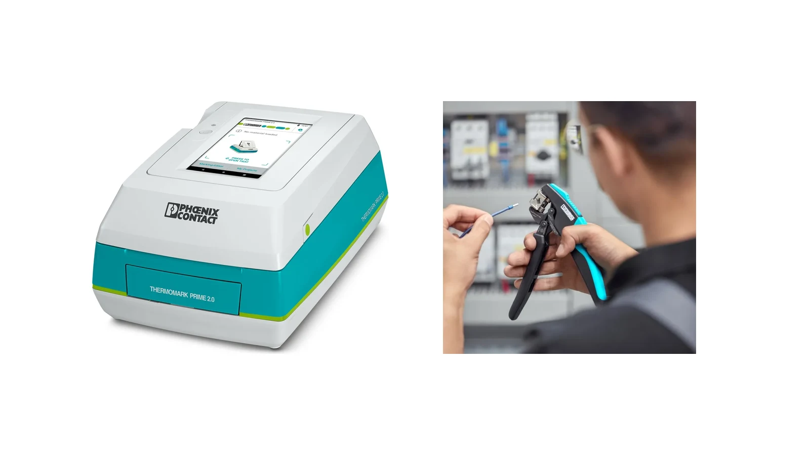
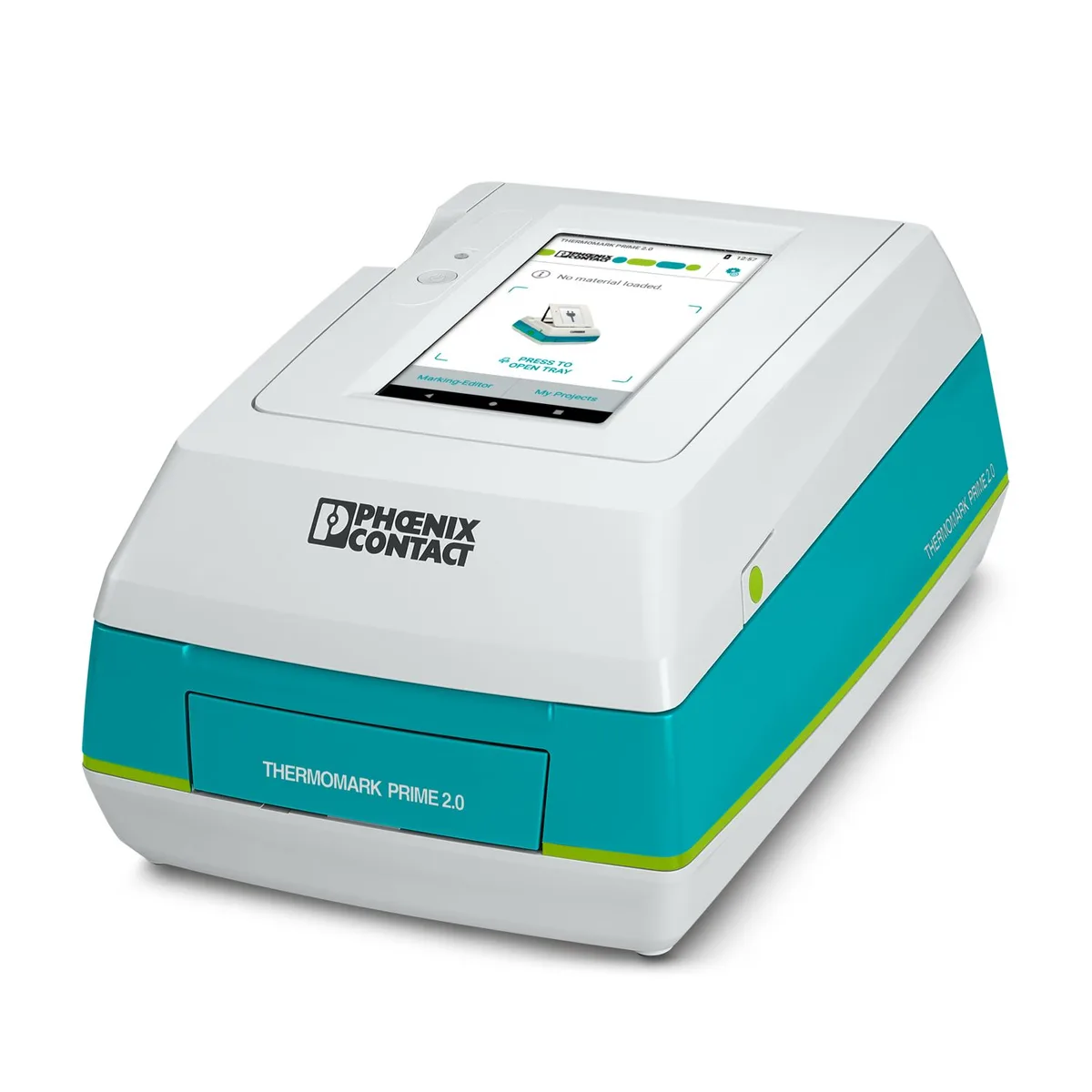
According to the product page, the THERMOMARK PRIME 2.0 is a thermal transfer printer designed for processing UCT, US, and UM card materials. It features a resolution of 300 dpi, a printing width of 104 mm, an integrated MARKING system, a 7-inch touch screen, and a removable battery, offering both stationary and off-grid usage options. These specifications correspond to the current product page with the order number 1472405. The compatibility of label material, cartridges, and ink strips must be verified based on the specific order code; it should not be assumed that older generations of consumables are automatically compatible.
When a more compact approach is required for maintenance and repairs in the field, THERMOMARK GO.K can be considered. The official product page specifies a printing width of up to 24 mm and a resolution of 203 dpi for continuous materials in cartridge format. This solution is suitable for processing various materials suitable for identifying wires/cables, equipment, and systems. However, the convenience of mobile use should not imply that project data can be altered uncontrolled in the field; label templates, character standards, and revision permissions must be strictly managed within the facility’s documentation process.
Automated marking for high volumes
The THERMOMARK E SERIES is a modular system that combines thermal transfer ribbon printers with various applicators. E.VARIO processes material continuously and cuts it at appropriate intervals to fit different marking channels in terminal blocks. E.SLEEVE cuts heat-shrink tubing to the required length and opens it for easy application. E.WIRE is designed for applying both movable and fixed cable labels, while E.WRAP is used for self-laminating wraparound labels on cylindrical surfaces. The manufacturer claims various time-saving benefits based on specific manual comparisons; however, actual performance should be verified considering factors such as product mix, data quality, operator efficiency, and feeding conditions.
The decision to automate a process should not be based solely on the printing time. If the device and wire labels in the CAE data are incomplete or inaccurate, a faster printer will simply reproduce the same errors at an even higher rate. It is essential to establish clear naming conventions, define data sources, implement recurring label verification processes, and establish effective change management procedures. The MARKING system software is designed to centrally manage Phoenix Contact’s marking systems and assign projects to specific devices. The official documentation also discusses how project and status information can be exchanged via two-way OPC UA communication using the THERMOMARK E SERIES. If network integration is required, additional considerations should be given to the software version, access permissions, and the cybersecurity policies of the facility.
Distinguishing terminal, cable, equipment and plant labels
| Marking task | Phoenix Contact solution to consider | Point to verify in the project |
|---|---|---|
| Terminal block series | Card, strip, or continuous material that is compatible with the terminal block family and label channel. | Pitch, channel geometry, character height, and visibility with bridges and accessories installed |
| Conductor wire or cable | Sleeve, label, heat-shrink tubing, or wraparound label | Range of diameters, cable movement, pre-/post-application assembly, and readability at both ends. |
| Equipment inside the control panel | Equipment labels that are detachable, lockable, or adhesive in nature. | Surface, mounting method, detachability, text area, and compatibility with the device. |
| Control panel, field box, or facility. | Sheet and equipment labels | External environment, UV rays, chemicals, temperature, viewing distance, and fixation method. |
| Centralized high volume processing | Thermal transfer, UV LED, or laser desktop systems | Material portfolio, batch size, color, quality control, and consumption planning. |
| Field and maintenance | Mobile options such as the THERMOMARK PRIME 2.0 or THERMOMARK GO series. | Compatible media, power supply, project transfer, and revision capabilities. |
Select hand tools for the operation
Phoenix Contact’s range of electrical tools is categorized into separate product families for cutting, stripping, crimping, screwdriving, testing and measuring, as well as for electronic applications. CUTFOX cutting tools are designed to cut cables without damaging their structure or causing unnecessary deformation of the conductors. The manufacturer indicates that cables with a diameter of up to 100 mm can be processed using different versions of these tools; however, this does not represent the maximum diameter that a single tool can handle. The type, diameter, and material of the cable must be selected in accordance with the current technical specifications of the appropriate cutting tool.
WIREFOX stripping tools offer various geometries for both standard and special insulation applications. For example, the WIREFOX 2.5 product page specifies a stripping range of 0.08–2.5 mm², a stripping length that can be adjusted up to 15 mm, and an integrated cutting function. However, these specifications are not necessarily applicable to all tools within the same product family. To ensure proper insulation removal, it is essential that the conductors are not damaged or cut, any remaining insulation does not enter the contact area, and the length of the exposed conductors remains within the range specified by the terminal manufacturer. Initial inspections and routine checks can be performed using a magnifying glass or appropriate measurement methods.
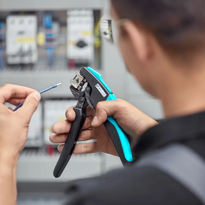
CRIMPFOX crimping tools offer dedicated solutions for various types of lugs, cable ends, and contacts. The official website explains how the integrated pressure locking mechanism and optimized force transmission in the appropriate tools contribute to process reliability and ergonomics. The crimping geometry, die, contact element, and conductor cross-section form a complete system; it should not be assumed that two lugs with similar appearances can be processed using the same die. The required verification measures and pull-test requirements must be determined based on the standard of the contact element used and the corresponding quality specifications.
The SCREWFOX product family includes standard screwdrivers, special tips, as well as cordless or torque-adjustable options. To properly tighten a terminal screw, it is essential to consider the tip geometry, dimensions, and the manufacturer’s recommended torque value. Excessive torque can damage the body of the screw or the component being fastened; insufficient torque, on the other hand, can reduce the quality of the connection. TESTFOX measuring instruments are designed for commissioning and inspection tasks, while MICROFOX tools are specifically for use with PCBs and in precision electronics applications. The selection of measuring instruments must take into account the voltage level, calibration requirements, and the need for personal protective equipment, in accordance with established electrical safety procedures.
Assembly systems: from DIN rails to cable routing
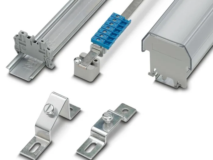
Phoenix Contact’s mounting components include DIN rails, neutral bars, rail stoppers, cable connectors, and various mounting adapters. The manufacturer offers options in NS 15 and NS 35 top-hat profiles, as well as NS 32 G profiles and limited C-profile variants. NS 35 rails are available in heights of 7.5 mm and 15 mm, and in different materials, as well as perforated and non-perforated versions. However, this diversity does not mean that any given rail is suitable for every component or application. The type of rail, material, corrosion resistance, mechanical load capacity, grounding method, and mounting holes must all be confirmed according to the product specifications.
Track stops limit the lateral movement of the terminal block assembly. End caps, profile covers, and adapters further enhance mechanical integrity and provide protection against accidental contact. Neutral busbar carriers are available in various configurations to adjust the height of the busbar relative to the track and mounting panel. Cable ties and cable channels are used to organize the conductors; the CGS cable routing system is specifically designed for pathways extending from the panel cover to the equipment’s body. For movable cover assemblies, the opening angle, minimum bending radius, friction factors, and service margins must be carefully tested on actual prototypes.
RailFIX and pre-assembled DIN rails
The RailFIX mounting adapters are designed for the subsequent installation of pre-assembled DIN rails on a control panel. The procedure described on Phoenix Contact’s official website includes preparing the control panel, inserting the adapters, positioning the rail at the guide and locking points, and completing the final fixation steps. This approach allows the assembly of components onto the rail to be moved to a separate workstation within the panel production process. However, the panel’s hole pattern, M5 connections, allowable load capacity, and installation instructions must all comply with the current application guidelines.
When pre-assembled rails are used, mechanical inspection alone is not sufficient—it is also necessary to verify the arrangement of terminals and heavy equipment, the load-bearing capacity during transportation, the pulling force exerted after cables are connected, and the integrity of protective connections. For rail sets transported between the production cell and the panel assembly area, adequate packaging and labeling measures must be in place. Even if the digital product documentation is accurate, scratches on the marking materials or misalignment of terminals can still lead to errors in the field.
The complete panel manufacturing workflow
- Clean the data: Verify the uniqueness of device, terminal blocks, wires, cables, and facility identifiers in the ECAD project; only the approved version should be sent for printing.
- Separate the marking task from other tasks: Separately record the environmental, dimensional, installation, and readability requirements for terminal blocks, conductors, equipment, and facility labels.
- Establish a printer/material matching system: Verify thermal transfer, UV LED, or laser technology against the official compatibility data for the selected card, roll, sleeve, or plate.
- Describe the preparation recipe for the conductor: Specify the cut length, strip length, ferrule or contact, crimp geometry, and tool code for each cable.
- Perform initial part inspection: Before mass production, verify the integrity of the conductors, the length of the exposed conductors, the clamping method, the content of the labels, and the readability of the barcodes.
- Prepare the installation infrastructure: Compare the dimensions of the DIN rail, adapter, stopper, neutral busbar, cable channel, and cover connectors with those specified in the mounting panel drawing.
- Keep track of cable connections and torque values: Follow the connection method outlined in the product instructions; use a calibrated torque tool and perform traceable inspections at the required points.
- Create an as-built revision: Re-input the changed label information, cable length, or mounting components into the digital project, and update the maintenance list accordingly.
Information required for a quotation
- Annual number of control panels, number of labels per project, batch size, and expected variety of products.
- Terminal blocks, conductors/cables, as well as the dimensions, materials, colors, and mounting methods for equipment and facility labeling.
- Internal/external environment, UV radiation, temperature, oil, chemicals, moisture, wear, and the desired service life.
- Whether central, mobile, or automated printing is required; integration with existing data sources and software.
- Conductor type, cross-section range, outer diameter, insulation, and ferrule/contact family to be processed
- Quality criteria and shift volumes for cutting, stripping, crimping, screwdriving, and testing
- DIN rail profile, height, material, hole pattern, length, and the total weight of components mounted on it.
- Cable channel, cover transition, shield connection, neutral busbar, and service interface requirements
- The required technical documents, compliance certificates, software version, and operator training scope.
Once these data are prepared, Phoenix Contact’s marking, hand tools, and assembly products can be considered as part of a traceable production system, rather than individual components. Oskon can analyze the existing panel structure and production volume to ensure that the printer/material compatibility, conductor preparation tools, and assembly infrastructure are all properly matched within the same quotation. The specific order numbers, consumables, and accessories must be verified against the latest manufacturer data at the time of the quotation.