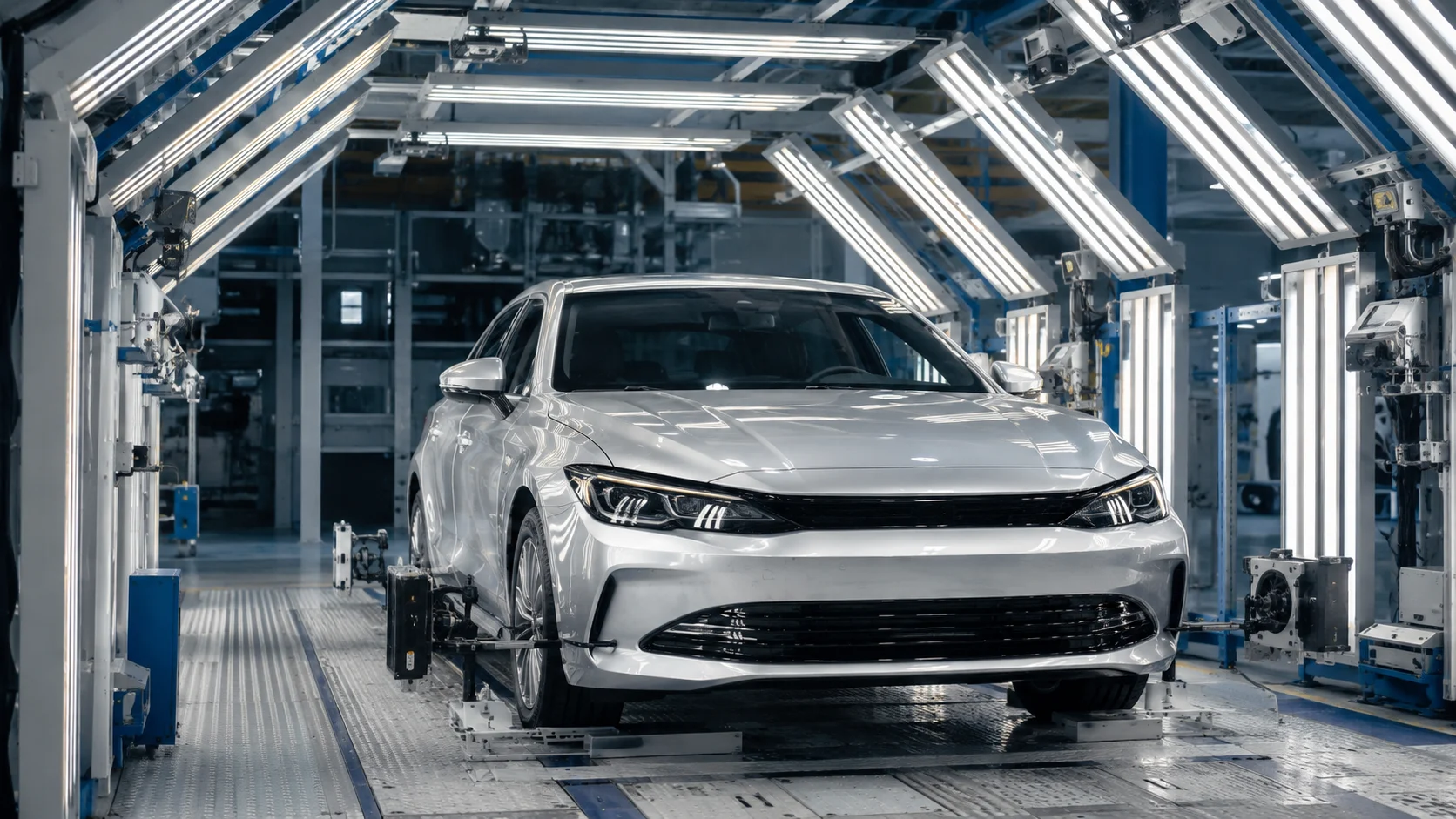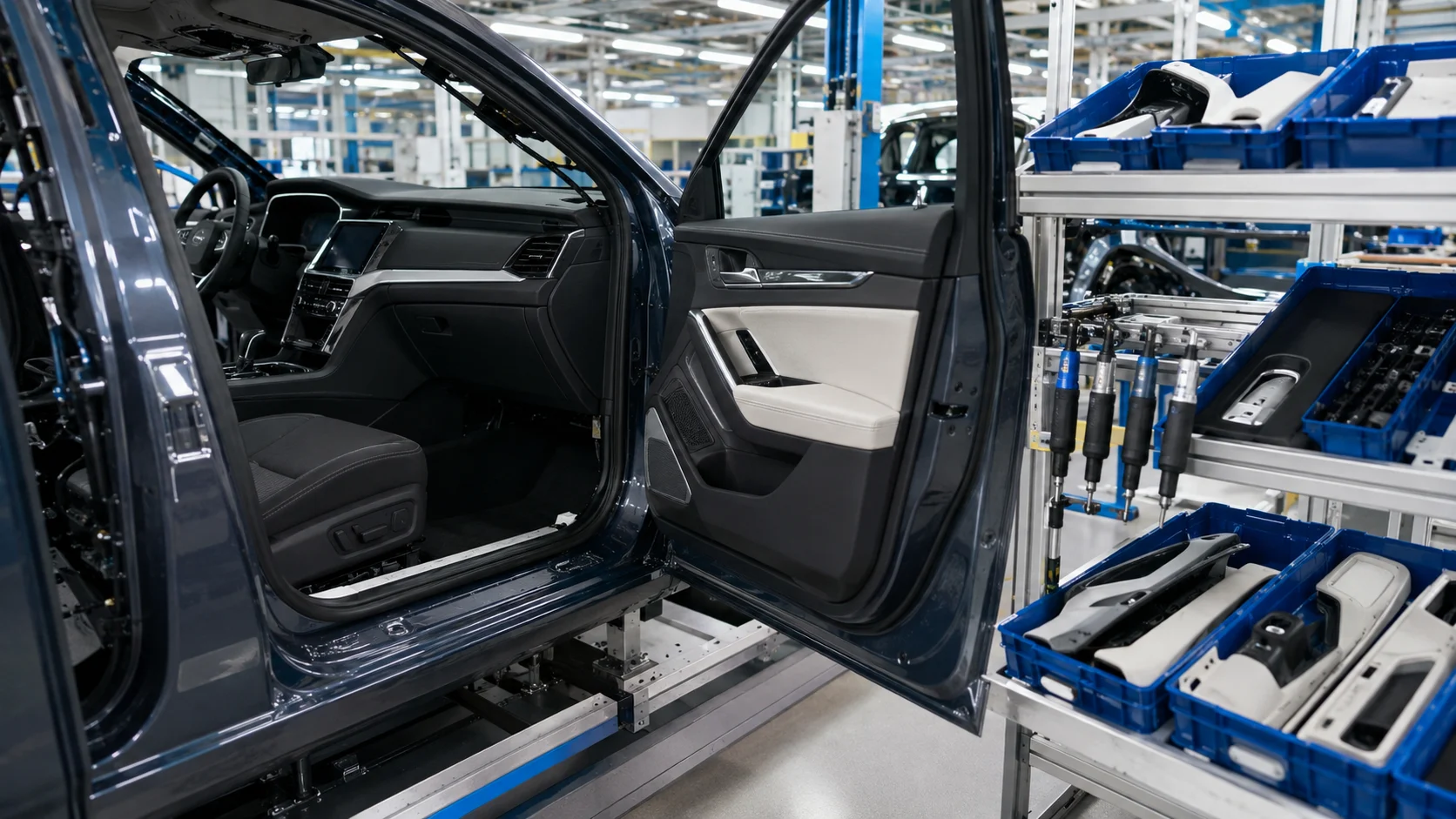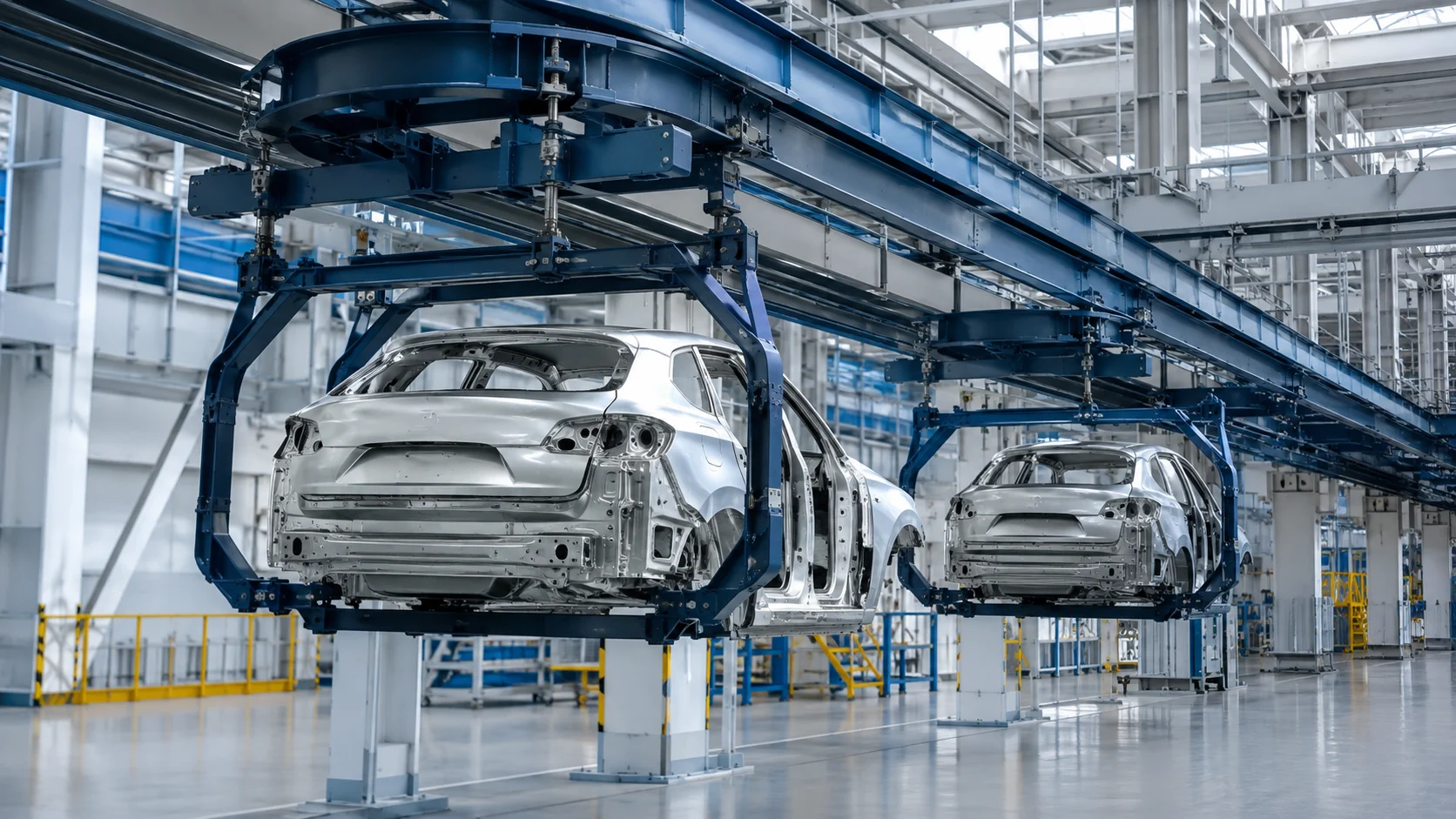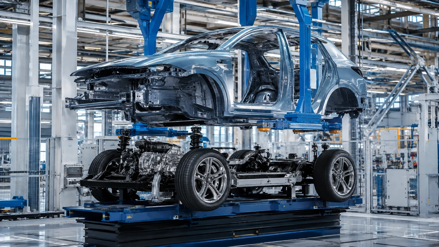
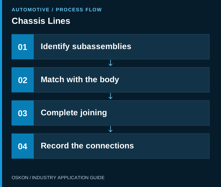
Match subassembly IDs, conveying positions and assembly results to the vehicle on chassis lines. A successful joining station brings the correct parts together in the correct sequence under verified conditions.
Translate the product structure into the station layout
The chassis line scope varies with the vehicle architecture; subassembly preparation, handling and joining to the body may take place at different stations. Define from the outset which subassemblies are tracked under which IDs, along with the assembly sequence and product variants. The mechanical layout follows this product structure.
Match subassembly and body IDs
The compatibility of axles, power transmission components, or other subgroups included in the project with the vehicle is confirmed based on the job order information. The identifier of the carrier component must not replace the identifier of the part it carries. In the event of part replacement or reprocessing, the relationship between these components is updated while the historical records are preserved. The sequence of actions required to prevent the wrong variant from being assembled is clearly defined.
Mechanical positioning and motion control work together
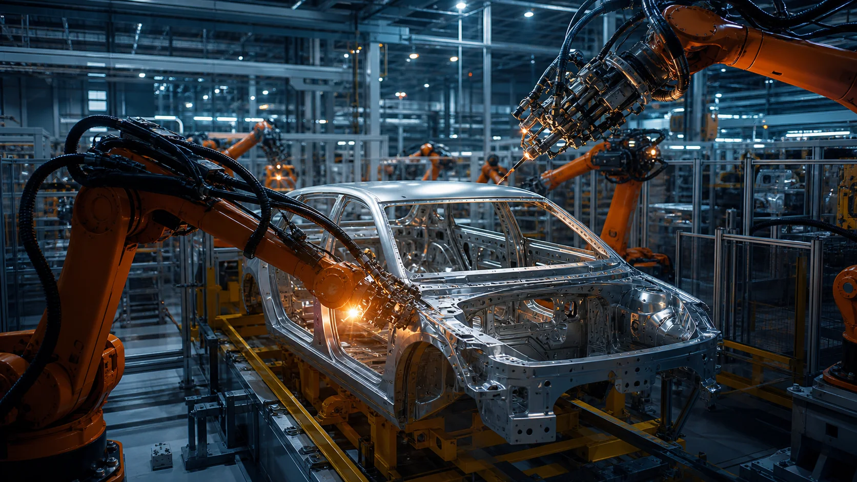
Coordinate datums, support points and lifting or positioning movements during joining. A movement-complete signal does not always prove that every mating surface is correctly positioned. Select the necessary position and process checks with the mechanical designers. Risk assessment determines how equipment reaches a safe state in the event of jamming, missing parts or unexpected load behaviour.
Add fastening results to the vehicle history
In controlled tightening operations, link the program, result and any required detailed process data to the fastening and vehicle IDs. Reworking a fastening must not erase its previous record. Display tool communication faults, unacceptable tightening results and operator cancellations as separate states. It must be possible to identify the first vehicle to which a recipe change was applied.
Carry incomplete-operation records forward to the next line
When an incomplete step is assigned to rework, the open task list follows the product. Production transfer and quality release are separate decisions. Record authorised interventions with reasons and timestamps. The operator interface should clearly show which subassembly is awaited and which fastening is incomplete. A generic error message unnecessarily prolongs troubleshooting.
Acceptance testing must cover different variants and interruptions
Identity matching, positioning, connection results, and top-level system transfer are tested end-to-end with actual products. Sequence changes, incorrect subassemblies, tool failures, and returns from incomplete cycles are all included in the validation process. Mechanical tolerances and control inspections are also taken into consideration. In this way, the assembly station is proven to function not only as a moving piece of equipment but also as a fully traceable assembly process.
Key information to monitor in the automation system
| Control point | Monitored information |
|---|---|
| ID compatibility | Matching vehicle and subassembly variants |
| Position verification | Mechanical readiness before joining |
| Fastening result | Vehicle-specific tightening and retry records |
Three questions to ask at the start of the project
- Are carrier and part IDs kept separate?
- Are incomplete fastening operations tracked as open tasks?
- Has recovery from an incomplete cycle been tested with an actual product?
Explore related applications
Explore related processes in Buffer Areas and Automatic Carriers and Telescopic Bars. Browse all Automotive articles or visit Automotive solutions.