Flow measurement is not an area where a single type of flowmeter can be used uniformly for gases, liquids, and bulk materials. The measurement of compressed air consumption, the volumetric flow rate of liquids in pipes, the prevention of pump dry running, and the volumetric flow of materials on conveyor belts all require different physical principles and installation guidelines. This catalog guide compares SICK’s current FTMg, T-Easic FTS, FFU, and Bulkscan product families based on their measurement capabilities. The technical specifications listed apply only to the specific family or model identified by its name and product number; the final choice should be made based on current data, process conditions, and practical field considerations.
Define the flow measurement task correctly
Before selecting the appropriate measurement method, such as “how many liters?”, it is essential to consider the physical state of the fluid and the specific requirements of the application. For example, in a cooling system, it may be necessary to verify that there is sufficient flow; in a filling machine, one might need to determine the total volume processed per cycle; in a compressed air system, information on consumption, pressure, and temperature trends is required; and on a mineral conveyor, the volume flow rate based on the material profile on the belt can be essential. The unit of measurement, the reference conditions, the update interval, the acceptable tolerance range, and whether the data is to be used for control purposes or simply for monitoring should all be specified in the initial paragraphs of the technical specifications.
Volumetric flow rate, the volume of gas converted to standard or normal conditions, mass flow rate, and the total amount measured cannot be used interchangeably. Since the volume of gas varies with pressure and temperature, the reference conditions must be specified clearly. In the case of bulk materials, a laser scanner does not measure the weight directly; instead, the volume is calculated based on the surface profile, and the mass is derived from the defined density. If the moisture content or particle distribution of the same material change, the accuracy of the calculated mass will also be affected.
Match the measurement principle to the application
| Product family | Medium and measurement principle | Main task | Most critical installation point |
|---|---|---|---|
| FTMg | Pressurized air and specified non-corrosive gases; flow/temperature measurement by calorimetry, pressure measurement by piezoresistance. | Consumption, leakage tendency, pressure, temperature, and energy visibility. | Gas type, reference conditions, pipe diameter, and selected communication protocol. |
| T-Easic FTS | Calorimetric probe immersed in liquid | Flow and temperature monitoring, limit monitoring, empty-pipe detection, and pump protection | Probe tip, pipe centerline, medium teach-in, and connection adapter |
| FFU | Conductive and non-conductive liquids; inline ultrasonic technology | Continuous volumetric flow measurement, totalization, and dosing support | Full pipe, no bubbles/cavitation, straight inlet/outlet, and chemical compatibility. |
| Bulkscan | Solid material being conveyed; laser flight time and belt speed. | Non-contact measurement of volume flow, profile, center of gravity, and derived mass flow rates | Empty belt reference, scanner geometry, encoder, and material density |
These four approaches are not successive, “more advanced” versions of each other. While T-Easic FTS is useful for flow threshold detection and pump protection, FFU offers a more suitable architecture for precise in-line measurement. FTMg is designed for monitoring gas flow and pneumatic energy consumption and is not suitable for use with liquids. Bulkscan, on the other hand, does not require any connection to the pipeline and is specifically designed for measuring material profiles on conveyor belts. The right technology is not necessarily the one that offers the most features; rather, it is the one that directly meets the specific requirements of the application, while allowing for acceptable levels of measurement uncertainty and maintenance needs.
Compressed air and gas monitoring: FTMg
FTMg is a family of multi-functional sensors that measure gas flow and temperature using calorimetric techniques, and process pressure via piezoresistive principles. According to SICK’s current product page, these sensors are designed for non-corrosive gases such as compressed air, argon, carbon dioxide, and nitrogen. They can provide up to eight process parameters, including flow rate, volumetric flow, total volume, mass flow, total mass, energy, pressure, and temperature. Their built-in seven-day data logging and statistical analysis functions help users monitor changes in consumption and detect potential leakage trends.
The connection architecture is selected based on the specific application. The industrial version includes switching/analog signals and IO-Link; the Ethernet version offers options such as web-based access, as well as REST API, MQTT, and OPC UA. However, the names of these protocols alone are not sufficient to ensure seamless integration. The PLC data map must specify parameters such as the sampling interval, reference unit, timestamp, network security settings, and the amount of historical data to be stored in the higher-level system. The pneumatic energy consumption value calculated by the FTMg should not be presented as a direct measurement of the electrical energy consumed by the compressor.
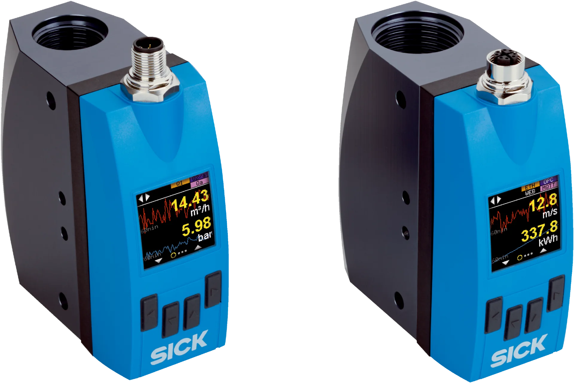
Variant example: FTMG-ISN50SXX
On the data sheet for the product with the model number 1122525, the FTMG-ISN50SXX, the following specifications are listed: connection dimensions of DN50 and 2-inch NPT; a standard measurement range of 58.9 to 11,780.9 liters per minute, with an extended range reaching up to 17,671.5 liters per minute; a process pressure of 0 to 16 bar and a process temperature of −20…+60 °C. The response time is stated to be less than 0.3 seconds, the communication protocol is IO-Link 1.1, and the body protection level is IP65/IP67. The flow rate values should be interpreted in accordance with the DIN 1343 reference conditions. These specifications are specific to this product number and must not be applied to other FTMG variants with different diameters or connection types.
In a compressed air line, the selection of the sensor diameter should not be based solely on the diameter of the main pipe, but rather take into account both the minimum, average, and maximum flow rates. A measurement diameter that is excessively large may limit accuracy at low flow rates, while one that is too small can lead to pressure losses and capacity issues. The quality of the gas, as well as the contents of condensate and oil, the arrangement of filters, and the flow direction, must be monitored in accordance with the operating instructions. If leakage detection is required, the base flow rate, as well as shift and recipe information, must be recorded on the same time axis during periods when production is halted.
Liquid flow monitoring and pump protection: T-Easic FTS
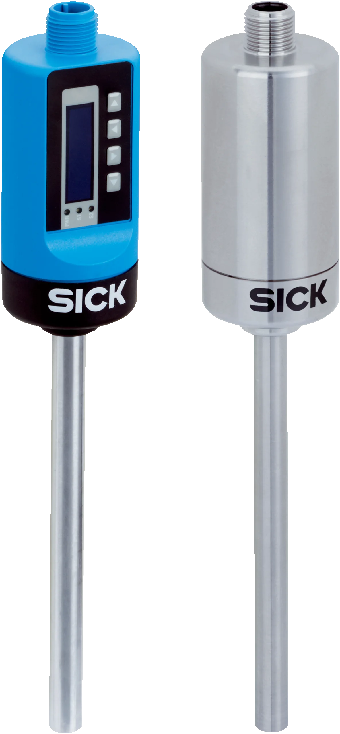
The T-Easic FTS measures flow rate and temperature in a calorimetric manner using a probe that extends into the liquid. SICK provides pre-programmed settings for water and oil, as well as the option to customize these settings for other liquids. The integrated empty-pipe detection function evaluates the contact between the probe tip and the medium, providing an additional safety mechanism to prevent the pump from running dry. The device comes with digital outputs for limit monitoring, a pulse output for volume measurement, an analog output for continuous value monitoring, and the ability to configure parameters via IO-Link. The specific output configuration is determined by the selected model’s data sheet.
The industrial models with VISTAL housings and displays and those made of hygienic stainless steel belong to the same family but are designed for different applications. The current product page specifies IP67/IP69 protection levels, IO-Link 1.1 compatibility for these models, while the hygienic variants are compatible with CIP/SIP protocols and can operate in process temperatures up to 150 °C. However, this maximum temperature does not mean that all connecting components are suitable for such conditions. Gaskets, T-piece fittings, welding adapters, and pipe materials must all be verified to meet their respective performance requirements.
Variant example: FTS-I061F14A
For the FTS-I061F14A with the product number 1114951, the official data sheet specifies a flow rate range of 3–300 cm/s for water and oil in pipes with a diameter of at least 25 mm, and 3–600 cm/s for a taught-in medium, with a 60 mm probe. The sensor can operate within temperature ranges of −40…+150 °C and pressure ranges of −1…100 bar; however, the actual process pressure allowed may be lower, depending on the selected T connection. The same data sheet also indicates that the sensor requires straight inlet and outlet runs of 5 × DN and 3 × DN, respectively. This example demonstrates that both the sensor itself and its mounting accessories play a crucial role in determining the measurement capabilities of the device.
The probe tip must be placed within the representative flow area inside the pipe and kept away from any walls or surfaces that could affect the flow. If the flow profile is disrupted due to the presence of elbows, valves, pumps, or narrow sections near the sensor, the measurement results may become unreliable. It should not be assumed that previous calibration settings will still be applicable to a new type of fluid when the operating conditions change. If dry-run protection is being used, the switching threshold, response time, pump shutdown duration, and the normal operating conditions of the process must all be tested in actual operating conditions.
Inline liquid flow measurement: FFU ultrasonic sensors
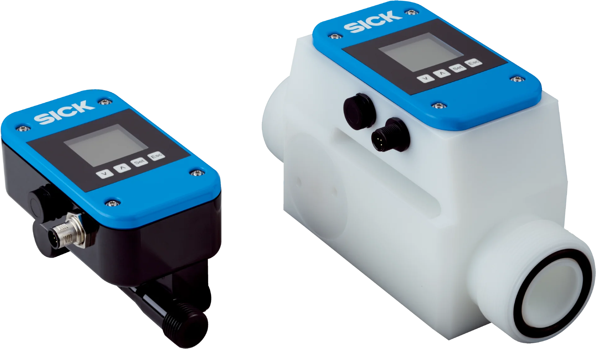
The FFU measures the volumetric flow of conductive and non-conductive liquids using non-contact ultrasonic technology. The term “non-contact” here does not mean that the sensor is clamped outside the pipe; rather, the measurement channel is located inside the process line, but no moving parts are involved in the measurement process. SICK’s product page lists the following features as standard: a high-quality polysulfone measurement body without seals, IP67 protection, integrated empty pipe detection capabilities, process temperatures up to 80 °C, and process pressures up to 16 bar. The exact pressure range may vary depending on the specific connection and model selected.
In ultrasonic in-line measurement, it is of critical importance that the pipe is completely filled with the fluid, that there are no excessive air bubbles or cavitation within the fluid, and that the required straight inlet and outlet runs are provided. Chemical compatibility should not be assessed solely based on the general material composition of the device; compatibility with the specific process conditions—such as temperature, concentration, cleaning agents, and contact duration—must also be verified. If data acquisition is performed via pulse output, the volume per pulse must be selected to suit the maximum frequency of the PLC counter.
Variant example: FFUC25-1N1SR
The data sheet for the FFUC25-1N1SR with the product number 6056879 specifies a DN25 connection, a 1¼-inch NPT thread, a measurement range of 5 to 240 liters per minute, a process temperature of 0 to 80 °C, and a maximum pressure of 10 bar. The same document also mentions a 40-cm inlet and a 20-cm outlet with straight sections, as well as analog current outputs and pulse/status outputs. The calibrated accuracy claim is dependent on conditions such as non-gaseous water, a fully filled pipe, no cavitation in the flow, and compliance with the specified stabilization requirements. It should not be assumed that the same accuracy level will be maintained outside of these conditions.
Bulk materials on conveyor belts: Bulkscan
Bulkscan scans without contact the surface profile of bulk materials on a conveyor belt using laser time-of-flight measurement. The difference between the reference profile of the empty belt and the measured profile of the loaded belt, when combined with the belt speed, provides information about the volumetric flow rate. The system is capable of recording the total amount of material, calculating the mass flow based on the known material density, and even determining the center of gravity of the load to indicate whether it is being loaded unilaterally. The direct measurement provided by this method is the volumetric profile of the material; the accuracy of the mass calculation, however, depends on the accuracy of the density input.
The latest SICK product page highlights the LMS511-based Bulkscan model’s robust features designed for harsh outdoor environments, such as multiple echo evaluation, an IP67-rated housing, and integrated heating. On variable-speed belts, encoder data is essential for accurate volume measurements. It is also crucial to ensure that the scanner’s line of sight is not blocked by fixed structures or dust accumulation; proper empty-belt calibration must be performed, and belt tension as well as the loading geometry need to be carefully monitored. Additional information, such as the material’s height and center of gravity, can be utilized to enhance process safety.
The data sheet for the LMS511-20190, with the product number 1059529, specifies the following specifications: a 905 nm class 1 laser, an operating range of 0.5 to 20 m, scanning options at 35/50/75 Hz, five echo evaluations, a band speed of up to 30 m/s, IP67 protection, and an operating temperature range of −40…+60 °C. It is equipped with Ethernet, RS-232/RS-422, USB, and digital I/O interfaces; if an analog signal is required, an additional BAM100 module must be used. These specifications apply exclusively to the specified model of this scanner.
Sizing and installation checks
The dimension of the flowmeter should not be determined merely by the name of the pipeline or the connection thread. Information such as minimum, normal, and maximum flow rates; process pressure and temperature; allowable pressure loss; measurement accuracy; response time, and the need for data accumulation must be specified in writing. For liquids, parameters like viscosity, conductivity, gas content, solid particles, cavitation, and chemical compatibility should be recorded; for gases, the type of medium, humidity, oil content, and reference conditions must also be noted. The installation direction and the requirement for straight pipelines should be indicated in the operating instructions according to the layout of the piping system.
The measurement point must be accessible for maintenance; the display screen must be readable, and the connector must remain readily accessible. In cases where heavy pipe loads are present, these should not be transmitted directly to the sensor body; appropriate supports must be used instead. For hygienic applications, the suitability of the dead volume design, drainage systems, surface conditions, and connection features must be assessed for the entire mounting assembly. When using bulk materials, the scanner bracket must be sturdy, the empty-belt reference must be maintained, and proper cleaning procedures for the window areas must be established. No matter how carefully a sensor is selected, it cannot compensate for incorrect installation geometry.
Information required for a quotation
- The name of the medium, its gas/liquid/solid state, composition, density, and expected variations.
- Minimum, normal, and maximum flow rates; desired unit of measurement, reference conditions, total quantity, and tolerances.
- Inner diameter of the pipe, connection standard, pressure, temperature, straight line length, and available mounting distance.
- Probe or inline installation; seals, wetted materials, hygiene, and cleaning requirements
- For conveyors: belt width/velocity, scanner distance, material profile, as well as dust and environmental conditions.
- Analog, pulse, digital, IO-Link, Ethernet, and requirements for higher-level system protocols.
- Control cycle, alarm/threshold behavior, data recording interval, and reporting objectives.
- Required calibrations, certifications, acceptance tests, spare parts, and maintenance services.
Commissioning and acceptance testing
During commissioning, zero flow, normal operating conditions, and, if possible, a known reference point are measured. The unit of measurement and the reference conditions must be consistent on both the PLC/HMI and the sensor display. The analog signal range, peak values, IO-Link process data, and network register settings are all recorded. The low and high alarm thresholds are tested in conjunction with actual process conditions. If a totalizer is used, a reference quantity is measured over an adequate period of time, rather than comparing instantaneous flow rates over a short interval.
The maintenance plan varies depending on the technology used. For the FTMg line, key parameters include gas quality and consumption; for the T-Easic FTS system, accumulation on the probe and the validity of the teach-in process are monitored; for the FFU, factors such as the fill level of pipes, the presence of bubbles, and the chemical compatibility are checked; for the Bulkscan system, the optical window, brackets, encoder, and the status of the empty belt are monitored. Parameter backups, product numbers, software versions, and recent inspection results are all recorded in the facility documentation. In this way, the flow data becomes not just a temporary value displayed on the screen, but a reliable and traceable process variable that can inform decisions regarding energy consumption, quality control, and maintenance schedules.
Official SICK resources
- SICK: Product category for flow sensors
- SICK FTMg product family
- SICK T-Easic FTS product family
- SICK FFU product family
- SICK Bulkscan product family
- Official data page for FTMG-ISN50SXX (1122525)
- Official data page for FTS-I061F14A (1114951)
- Official data page for FFUC25-1N1SR (6056879)
- Official data page for LMS511-20190 (1059529)
- SICK DOSIC archive product record
- SICK DOSIC official catalog – Life cycle documentation
- SICK and Endress+Hauser announce their partnership in process automation.