Automatic identification refers to the process of matching a product, carrier, pallet, crate, or production component with the correct record at the appropriate moment. A successful system consists not only of devices capable of reading codes, but also requires careful consideration of various factors such as the quality of the markings, triggering mechanisms, reading ranges, object speeds, data verification, integration with PLCs or software, and contingency plans for cases where codes cannot be read. SICK’s portfolio of automatic identification solutions includes camera-based code readers, fixed-barcode scanners, RFID readers/writers, mobile handheld terminals, as well as the connecting components and software needed to turn these devices into fully functional system solutions.
The real purpose of an AutoID system
The mere appearance of a barcode on the screen does not constitute a sufficient measure of success. The reading result must be assigned to the correct object, verified against the corresponding production order or shipping record, and then transmitted to the subsequent equipment in a timely manner. If two boxes on a conveyor are too closely spaced, the correct reading may be associated with the wrong box. If a code is read twice, it may lead to duplicate inventory movements. In the absence of a physical separation mechanism for unread codes, even if the system generates the relevant data, operational control will be lost.
Therefore, the AutoID project is implemented in three layers: the device that physically captures the identifier; the control layer that associates the reading result with object and time information; and the processing layer that transmits the result to systems such as WMS, MES, ERP, or tracking applications. The SICK device serves as the detection point in this chain, and the overall system performance depends on the proper functioning of all three layers.
When should each identification technology be selected?
Camera-based code readers
Image-based readers can decode 1D, 2D, Data Matrix codes, or any other types of codes supported by the specific product, by analyzing an image. These readers are particularly useful in applications where the orientation of the code may change, where code quality needs to be monitored, where direct part marking is required, or where it is essential to retain the image in case of failed readings. The lens, focus settings, resolution, illumination color, and polarization properties are selected based on factors such as code size, cell dimension, surface texture, and working distance. Simply having a “higher number of megapixels” does not necessarily guarantee better reading performance; the overall optical performance also depends on the number of pixels per code cell and the exposure time used.
Fixed laser barcode scanners
Laser scanners are an excellent option, especially for high-speed reading of 1D barcodes. Their wide depth of field and adjustable scanning lines enable them to adapt to various box heights. The orientation of the code, the layout of the scanner, and the geometry of the conveyor system are all important factors. If multi-directional reading is required, multiple scanning lines or a multi-faced system architecture may be necessary. In cases where damaged 2D codes are present, or if OCR or image recording is needed, comparisons with camera-based technologies should be considered.
RFID identification
RFID utilizes radio waves between the transponder and the reader; its key advantages include the lack of the need for a direct line of sight, as well as the ability to write data onto tags in suitable systems. It can serve as an alternative to optical codes for objects that are dirty, enclosed, or have variable orientations. However, factors such as metal presence, liquids, antenna polarization, frequency band, tag type, and the presence of multiple transponders in the same area can affect reading performance. UHF, HF, and other frequency categories do not share the same range and application characteristics. When choosing an RFID system, factors such as tag cost, reusability, data security, and regional radio regulations must be taken into consideration.
Mobile and magnetic solutions
In cases where the operator approaches the object for re-reading or exception handling, mobile handheld terminals offer flexibility. Magnetic code identification can serve as an alternative to optical and RFID technologies in specialized transportation or positioning applications. If, within a fixed automation system, the handheld terminal is used solely for error correction rather than as the primary reader, the process permissions and software interface must be designed accordingly.
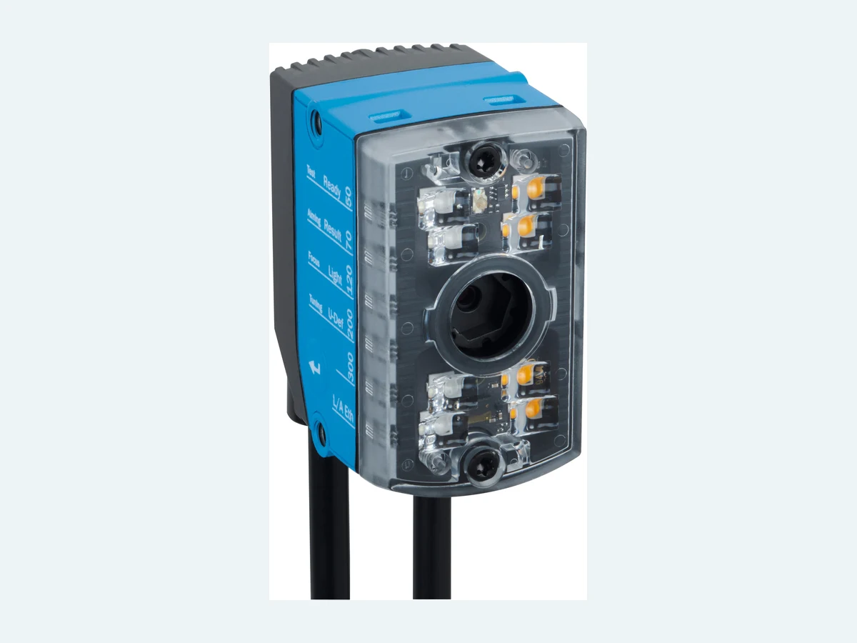
Critical design data for camera-based reading
The first piece of information in a code refers to its type and physical dimensions. In a two-dimensional code like Data Matrix, both the total external dimensions and the size of each individual cell are important factors. If the code is directly laser-engraved onto metal, its contrast differs from that of a printed label. On shiny plastic packaging, reflections may occur; on curved surfaces, parts of the code may fall outside the focal range. The speed at which the product moves determines the exposure time, and the exposure time, in turn, affects the clarity of the code.
The reading range is not a fixed value. It is determined by considering the working distance, the field of view, and the desired code resolution, all in conjunction with the minimum and maximum heights of the product. Within the Lector series, there are various product models designed for different applications, such as compact designs or wider fields of view. For example, the Lector61x series is a camera-based reader designed for use in confined mounting spaces or for reading small codes; the actual resolution, focal range, lighting requirements, and interface specifications should be confirmed by referring to the product data sheet for the specific model selected.
Illumination is just as important as cameras. Internal lighting can simplify many applications; however, bright surfaces, color-printed codes, or deeply engraved markings may require external lighting, different colors, diffusers, or polarization techniques. The angle between the reader and the product can be adjusted to minimize reflective interference from mirrors. For this reason, in sample testing, it is essential to use not only new and clean codes but also the weakest codes that the manufacturing process is capable of producing.
How to design an RFID read point
In RFID, the goal is not to achieve “the longest possible range” but rather to read the desired tag reliably without reading unwanted adjacent tags. The range of detection is determined by factors such as antenna power, antenna type, cable loss, polarization, the placement of the transponder, and any reflective surfaces in the vicinity. In environments like forklift areas, passageways with gates, or conveyor tunnels, the metal structures, as well as the geometry of the motors and loads, must be taken into account when mapping the reading areas.
The surface onto which the label is applied is also an important factor. A standard label applied directly onto metal may detune the tag antenna; packaging containing liquids can affect the UHF signal. In such cases, an “on-metal” label, additional intermediate components, or a different antenna configuration may be required. If the orientation of the label is not fixed, circular polarization or the use of multiple antennas may be necessary. When multiple readings are to be taken, the maximum number of transponders that can be present in the area at the same time and the processing time required must also be taken into account during the acceptance testing.
Triggering, object tracking and result assignment
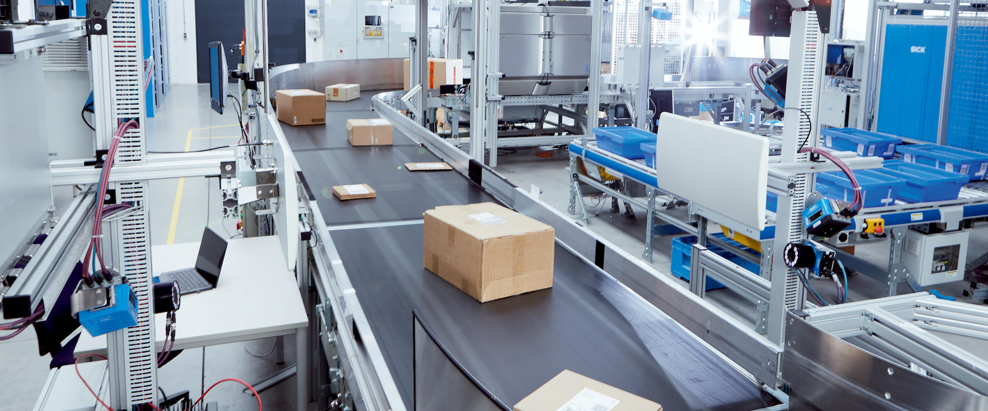
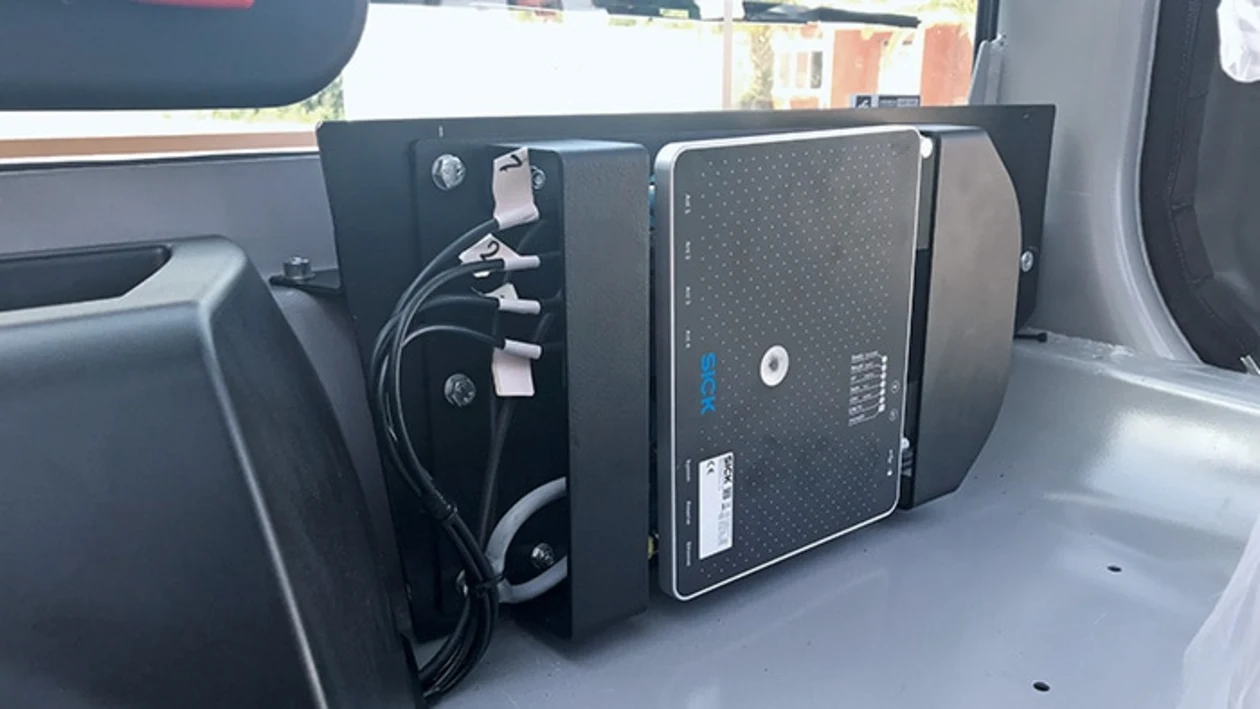
When a fixed reader is required to collect data, this can be determined via photoelectric triggering, an encoder, a PLC command, or a free-running configuration. If the conveyor speed varies, distance-based tracking may be more reliable than time-based delays. When the distance between two products decreases, the triggering windows must not overlap; in a multi-faced system, the results from different readers must be combined to identify the same object.
When multiple codes are present, the selection criteria must be clear. Filtering can be performed based on code type, prefix, length, check character, or a predefined list of expected codes. The “first code read” is not necessarily the correct code; supplier and logistics labels on the package may be within the same field of view. Additionally, information such as reading time, device identity, quality criteria, and, if necessary, image references can be transmitted to the higher-level system.
The read failure management mechanism is designed based on the physical flow of items. Should an unread item be stopped, separated, or sent to a manual station? The distance to the separator and the belt speed are monitored in real-time by the PLC. When re-reading is performed, the initial event must be canceled or combined with the same item. Any operator intervention is recorded along with the user’s credentials and the corresponding audit trail.
4Dpro and system integration
SICK’s 4Dpro concept aims to provide similar connection, configuration, and integration approaches across different identification technologies. Its operational value lies in the ability to adjust camera, laser, and RFID options according to project requirements, enabling maintenance teams to work with a common set of tools. However, it is essential to verify the protocol, connector type, software functionality, and cloning method supported by each device on a product-specific basis.
The readout data can be directly transmitted to the PLC, the industrial Ethernet network, or the higher-level system via the connection module. The cycle time, data volume, network segmentation, device addressing, time synchronization, and fault-handling procedures are determined during the architectural design phase. If image archiving is required, the retention period, access permissions, and potential implications regarding personal data also need to be addressed within the information security policy.
Performance acceptance criteria
A phrase such as “100% accuracy in reading” that is divorced from its context is not considered a technical specification. The acceptance test should specify the defined set of samples, product speed, product range, code quality, orientation, ambient light conditions, label position, and the required test duration. Metrics such as the initial reading rate, incorrect readings, duplicate readings, incorrect object assignments, and the ability to identify no-read cases are all separate evaluation criteria. In the case of RFID, unwanted readings of adjacent tags are also considered errors.
A system that performs well in a FAT environment may behave differently due to the metal structures present in the field or the effects of daylight. During the SAT phase, actual loads, maximum speeds, varying lighting conditions during different shifts, and the worst-case label samples should be used for testing. The results are cross-checked against device logs and higher-level system records. Once acceptance is confirmed, parameter backups, photos of the reading areas, and reference samples are added to the maintenance documentation.
Maintenance and lifecycle
For optical readers, cleaning the windows, checking the focus and brackets is part of regular maintenance. For RFID systems, connecting the antenna and cable, checking for mechanical damage, and ensuring the reading area is unobstructed are also essential maintenance tasks. Changes in packaging design, the introduction of a new label supplier, or the use of different pallet materials can all affect system performance. Any changes to the processing procedures should not be made without the involvement of the software development team; these changes must be re-verified using AutoID validation samples.
During device replacement, the IP address, parameter file, trigger logic, and system-level configurations must be restored in a controlled manner. Even if the replacement device belongs to the same family, its firmware and license may differ from the original device. Running a brief reference test package after the replacement helps prevent any hidden configuration errors from affecting production.
Oskon's AutoID project scope
Oskon designs the identification point in conjunction with the entire material flow process. The selection of code or label standards, sensor triggering mechanisms, readers, and accessories, as well as the related installation, cabling, PLC programming, logic for data processing, HMI displays, and data exchanges via WMS/MES/ERP systems, are all integrated within a single functional concept. When necessary, barcode, camera, and RFID technologies are also utilized for comparison purposes; the final decision regarding which technology to adopt is not based solely on initial investment costs.
In automated warehouse management, sorting systems, production lines, or material tracking applications, the device ensures that the identifier of each carrier is accurately matched with its designated route. Alarm thresholds, retry mechanisms, manual verification procedures, and safe shutdown scenarios are all established as part of the system. In this way, SICK products cease to be mere components of a catalog but become an integral part of a comprehensive, end-to-end identification solution that meets rigorous measurement and acceptance criteria.
A short checklist before purchasing
- What are the types of codes, physical dimensions, cell sizes, and methods of printing or marking?
- What are the speed, height, direction of the object, and what is the minimum distance between the two objects?
- Will codes be read from one face, multiple faces, or independently of orientation?
- If RFID is to be used, what are the frequency band, tag type, material, and the number of tags in the area at the same time?
- How will the results be transmitted, which PLC or software will be used, through which protocols, and within what time frame?
- How should the physical flow be managed in cases of unread data, repeated readings, or incorrect assignments?
- Who is responsible for parameter backup, image storage, user permissions, and maintenance?
Frequently asked questions
Can a camera reader always replace a laser reader?
No. The type of code, speed, field of view, orientation, cost, and image requirements determine the appropriate choice. For 1D codes, laser scanners remain a strong option; whereas in cases where 2D coding, DPM detection, quality analysis, or image recording are required, cameras become the preferred solution.
Can RFID read every tag without line of sight?
The fact that it does not require a line of sight is a significant advantage; however, factors such as metal objects, liquids, the orientation of the label, the antenna range, and the performance of nearby transponders can all affect its functionality. The reading point must be tested using actual materials.
Can one reader cover the entire conveyor width?
Even if the field of view or scanning area appears sufficient, the code resolution, the height of the product, and its orientation may require the use of multiple devices. The system architecture for multi-face reading is also designed accordingly.