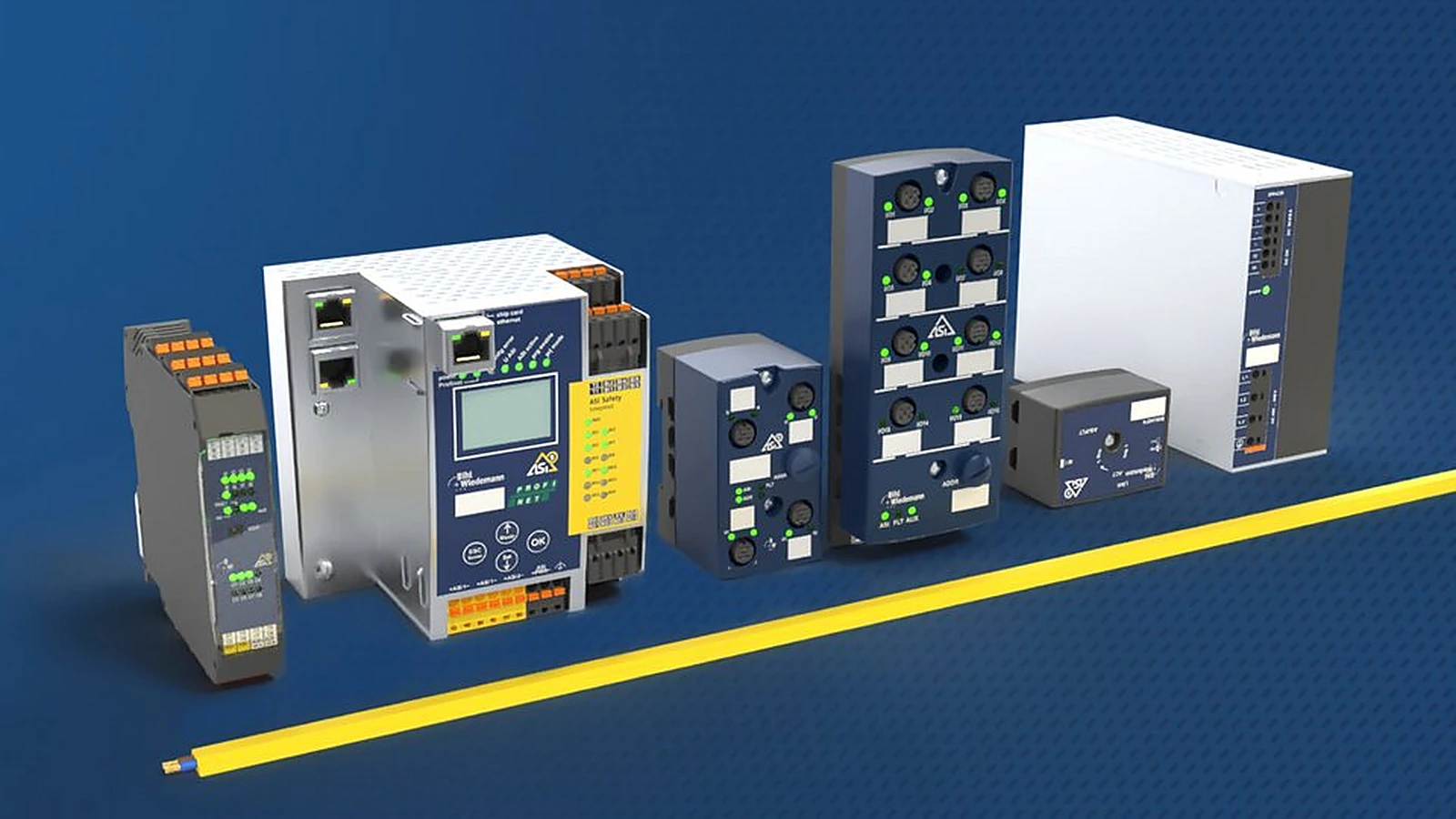
AS-Interface controllers, gateways and modules work together to connect numerous sensor and actuator signals to higher-level control in an organized, diagnosable and expandable architecture. Selection involves more than matching port counts. Consider the upper-level network, ASi generation, cycle time, process-data width, standard and safety-related signals, auxiliary power, cabinet environment and maintenance approach together. This guide presents the Bihl+Wiedemann portfolio through a sequence of engineering decisions.
The roles of gateways, masters and modules in ASi architecture
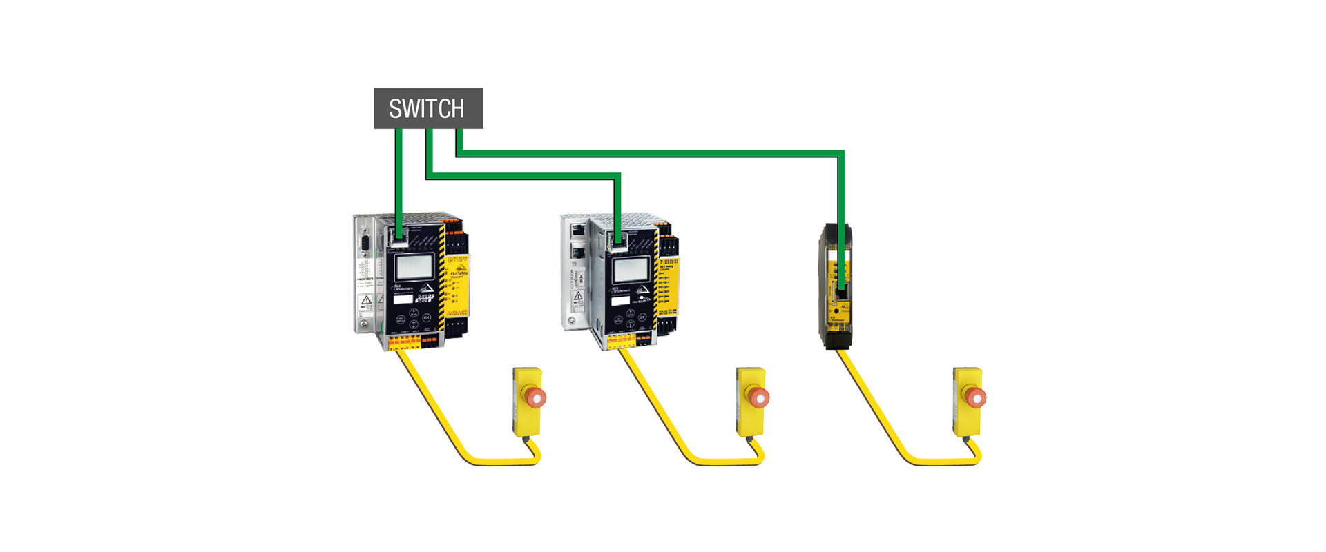
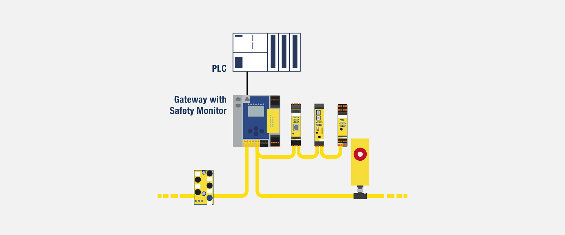
AS-Interface connects devices at the lowest automation level to higher-level control. Sensors and actuators may connect directly through ASi or through digital, analog or IO-Link modules. The ASi master manages cyclic data exchange; the gateway transfers that data to the PLC’s industrial network. Many Bihl+Wiedemann devices combine master and gateway functions. Specifying only ‘gateway’ therefore does not define the number of ASi networks or master generation.
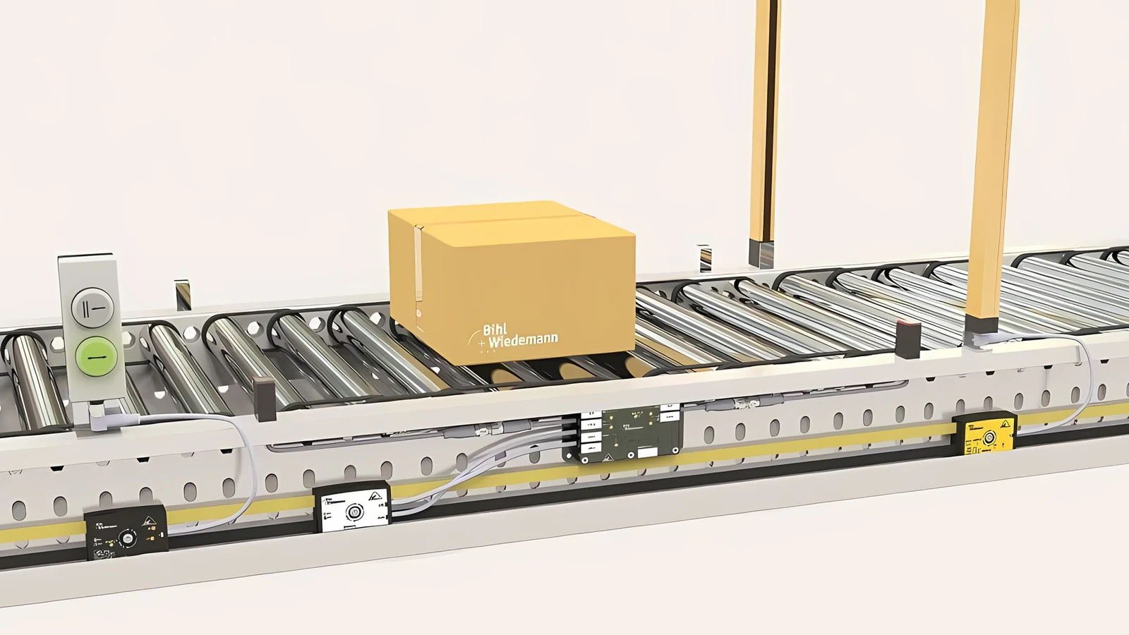
A module is the point where physical field signals enter or leave the ASi network. Signal type, connection, power source and protection rating matter as much as I/O count. An IP20 cabinet module with push-in terminals and an IP67 machine-mounted M12 module may carry the same data but have different installation, cabling and environmental requirements. Some gateways offer optional C programming for mini-PLC functions; this does not automatically make them the main machine PLC or a safety PLC.
Assessing ASi-3 and ASi-5 in the same project
Bihl+Wiedemann’s current product pages show ASi-3 and ASi-5 support across modern gateways and many modules. ASi-5 addresses wider process data, short cycles and integration of intelligent devices such as IO-Link equipment. The manufacturer describes system capabilities including a 1.27 ms cycle for 384 input and 384 output bits with a suitable profile, and up to 32 bytes of process data per node. These values do not apply automatically to every module: verify the master, selected profile, node count and product data width together.
Existing ASi-3 modules that only contain simple on/off signals do not need to be replaced unnecessarily just because new-generation products are available. New, data-intensive functions can be added using ASi-5, and both existing and new modules can be managed using the same automation approach via compatible gateways. However, the address capacity, cycle calculation methods, and diagnostic functions vary depending on the module generation. The ASi profile and address type of each device must be clearly specified in the as-built list; the label “ASi-compatible” alone should not be considered a sufficient acceptance criterion.
Selection steps for the right product family
- Record the PLC and the higher-level network: Independently of the controller brand, specify the protocol, device function, safety communication functions, and the required device configuration file.
- Split your ASi networks: Based on the machine’s geometry, node density, energy budget, standing areas, and maintenance considerations, decide whether to use a single or dual-loop control system.
- Create a data inventory: Count standard and secure digital I/O signals, analog values, IO-Link process data, parameters, and diagnostic bytes separately.
- Select the physical environment: Specify whether you require IP20 control panels, IP67 field-mounted devices, M8/M12 connectors, profiled cables, or open-ended/push-in terminals.
- Calculate your energy usage: Evaluate the ASi line and AUX power supply in terms of sensor performance, actuator functionality, initial current levels, current reduction depending on temperature, and cable voltage drop.
- Describe the diagnostic process and its lifecycle: Include web access, PLC alarms, backup configuration, firmware, certificate management, and spare parts management within the scope of the project.
BWU3852: a dual-circuit PROFINET gateway example
BWU3852, listed as a stainless-steel PROFINET gateway with two ASi-5/ASi-3 masters, is documented in the 29 July 2026 data sheet with two ASi networks, PROFINET and OPC UA, Ethernet diagnostics, integrated data decoupling and up to 4 A per ASi network. One supply can power both networks, but supply capacity, conductor size, protection and the actual load on each network must be calculated separately.
On the PROFINET side of the device, there is an integrated switch with two RJ45 ports, supporting 10/100 Mbit/s communication, PROFINET IO Device functionality, and MRP support. On the IT side, an OPC UA server, a web server, and a REST API are available. These components ensure data availability; however, user permissions, certificate management, network segmentation, and remote access policies must also be carefully designed. The presence of these interfaces does not necessarily mean that MES or cloud integration is secure and ready for use.
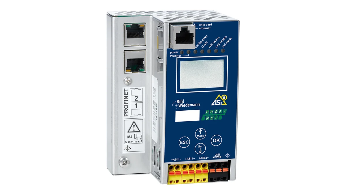
The gateway data sheet specifies a fixed 1.27 ms ASi-5 cycle for 384 input and 384 output bits; ASi-3 cycle time follows a node-count formula. Its LCD displays addresses and fault messages, with duplicate-address detection, ground-fault and interference monitoring. Diagnostics support troubleshooting but do not replace correct wiring and measurements. The DIN-rail device is IP20 with a stated non-condensing operating range of −25 to +55 °C. Do not treat it as a field enclosure; verify cabinet temperature and airflow under load.
Optional C programming enables mini-PLC tasks on the gateway, such as preprocessing, local logic or data organization. Before moving the machine’s main sequence there, assess resource limits, fault behavior, software ownership and maintenance tools. For functional safety, select a suitable safety-monitor or safety-fieldbus variant instead of the standard BWU3852, and independently validate the complete safety function.
BWU4267: flexible digital I/O density in the control panel
BWU4267 is an IP20 ASi-5 self-configuring I/O module with push-in terminals. Connections can be assigned to sensor and actuator tasks in different combinations, or a fixed input/output layout can be set in software. Depending on configuration, the data sheet specifies up to 16 digital inputs and 16 electronic digital outputs, one ASi-5 address and two bytes of process data. This does not mean that every channel performs both tasks simultaneously; the selected configuration determines the actual allocation.
The power supply for sensors and actuators is provided via the AUX interface. The output current, as well as the total power consumption of all sensors, are subject to limitations depending on the ambient temperature. For example, the data sheet specifies separate limits for each output channel and for each group of four channels; it also provides conditions such as the minimum distance required between adjacent devices when the system is used in temperatures above +55 °C. Therefore, it is not sufficient to simply compare the total amperage values. It is necessary to monitor the distribution of loads across different channel groups, as well as the synchronization of these processes and the actual temperature inside the control panel.
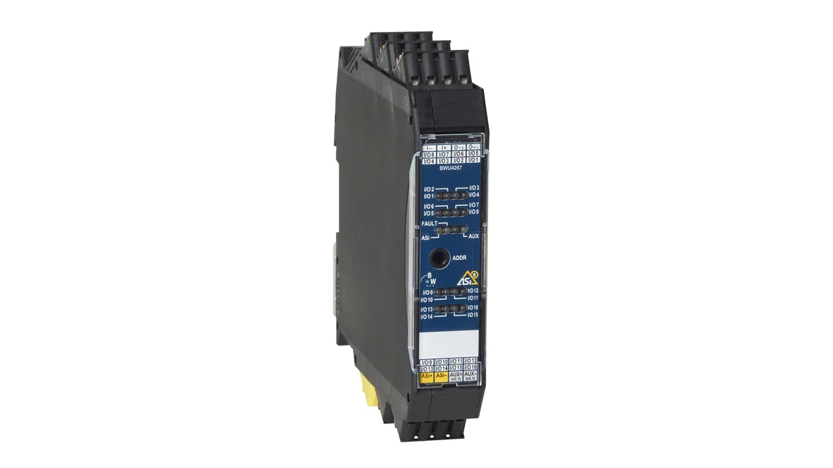
The dimensions of the module, 22.5 × 99 × 114 mm, are listed excluding the terminals. It would be incorrect to determine the panel depth based solely on the body dimensions, without taking into account the space required for cable bending and the movement of the removable terminals. The LEDs provide information on ASi status, AUX signals, channel status, short-circuit detection, and overcurrent conditions. The maintenance instructions should clearly indicate the meaning of each LED, the configured channel direction, and its corresponding address in the PLC. Failing to do so could lead to confusion during on-site operations due to a lack of self-configuring flexibility.
BWU3843: carrying IO-Link data over ASi-5
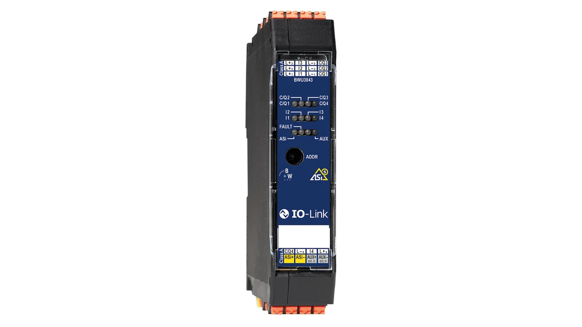
BWU3843 integrates a four-port IO-Link master into ASi-5 in an IP20 housing. The documentation lists configurable Class A or Class B connections, COM1/COM2/COM3 rates, IO-Link 1.1 and up to 32 bytes of process data plus one PQI byte per port. ASi process-data width is 16 bytes and depends on the selected ASi-5 profile. Do not assume all IO-Link parameter and diagnostic data fit automatically into the PLC cyclic process image.
The AUX power supply has a nominal voltage of 24 V. At temperatures up to +40 °C, a current of 500 mA per port is supplied, for a total of 2 A; higher temperatures result in reduced current levels. For Class B devices, the additional actuator power requirements and the need for galvanic isolation must be considered, along with the appropriate terminal assignments. Simply selecting Class B in the software is not sufficient to ensure adequate power supply for high-current loads. Whether the C/Q line is used as an IO-Link signal, a digital input, or a digital output, it must be specified in the same manner within the device parameters and electrical schematic.
Match module families to the signal task
| Requirement | Product group to consider | Detail to verify in the quotation |
|---|---|---|
| A large number of standard digital signals | IP20 or IP67 digital I/O module | Actual input/output configuration, channel current, power supply type, and address type. |
| Smart sensors and parametric devices | ASi-5 module with integrated IO-Link master functionality | Port class, process data profile, AUX power, and IODD signal flow. |
| Current, voltage, and temperature measurement | Analog I/O module | 4–20 mA, 0–10 V; measurement type: Pt100 or thermocouple; high resolution and channel isolation features. |
| Rapid pulse or frequency | ASi-5 counter or function module | Maximum frequency, signal bandwidth, cycle profile, and input voltage. |
| Guard door, emergency stop or safety output | Safety I/O and appropriate safety monitors/gateways | Channel architecture, PL/SIL calculation, test pulse, response time, and certifications |
| Conveyor roller or frequency inverter | Drive interface module | Motor protocol, voltage, current, regenerative energy, and safe stop behavior. |
Addressing, data profiles and device descriptions
When establishing an ASi network, the address table must be an integral part of the electrical design. Information such as the physical location, device label, product number, ASi address, profile, gateway settings, and PLC data fields should all be recorded on the same line. Although duplicate addresses may be detected by the gateway during commissioning, a controlled assignment process ensures greater reliability and prevents errors. In the case of a spare module strategy, it is essential to test the automatic address assignment behavior of devices with empty addresses and determine how to restore previous configurations.
For upper-layer network integration, the manufacturer’s current GSDML, EDS, or relevant device definition files must be used. These files must be included in the project archive, their version numbers must be recorded, and their module sequences must match those in the PLC engineering software. When the ASi-5 profile is changed, not only the node settings but also the gateway hardware catalog and PLC data mappings may need to be updated. The green status indicator on the configuration screen does not in itself guarantee that the physical output is connected to the correct load and exhibits the desired safety behavior.
Power and cable budgets are linked to communication
Although the ASi cable transmits both data and power, it is not necessary for every load to be powered from the same line. Sensor power can be supplied via ASi or AUX, while actuator power may be provided through a separate auxiliary line, depending on the product model. In addition to calculating the total current, factors such as voltage drop, simultaneous outputs, initial energization current, ambient temperature, and short-circuit protection must also be taken into account. The ability of two systems on a dual-master gateway to be powered from the same source does not imply that these systems must necessarily be combined with regard to electrical safety and shutdown procedures.
When using an AUX channel that is switched in a passive and safe manner, it is necessary to verify the compatibility of the selected module with this architecture by referring to the complete data sheet. Two different connection variants within the same family may have distinct error exclusion requirements. In the context of functional safety, simply disconnecting the power to the standard output does not necessarily ensure safe operation; the entire energy supply path, as well as the input of the contactor or drive, must be taken into consideration, along with any feedback and diagnostic mechanisms.
Commissioning and acceptance testing
- Document review: Match the full product numbers of the gateways and modules with their respective current data pages, device description files, and certificates.
- Control without energy: Verify ASi/AUX polarity, shielding and grounding, terminal tightness, address labels and cabinet segregation rules.
- Energize one ASi network at a time: Record the voltages under no-load and load conditions, as well as the gateway’s current measurement values and short-circuit protection responses.
- Node verification: Map every address to each physical sensor or actuator; exercise inputs, outputs and diagnostic bits during testing.
- Upper-layer network testing: Test PLC data mapping, reconnection, gateway power cycling and recovery from the backup configuration.
- Load test: In the most intensive cycle, monitor the ASi cycle time, the freshness of process data, the error counters, and the control panel temperature.
- Maintenance scenario: For the removal of a module, incorrect address settings, loss of the AUX function, or communication interruptions, confirm the corresponding alarm messages and the required corrective actions.
Cybersecurity and remote access boundaries
OPC UA, REST APIs, and web servers are valuable for maintenance and data collection purposes; they also represent network interfaces that require proper management. Gateways should not be arbitrarily connected to the control network, the corporate network, or the internet. Unnecessary services should be disabled, supported authentication and certification options should be utilized, and access should be restricted through firewalls and VLAN policies. Manufacturers’ latest security updates and firmware versions must be monitored throughout the device’s lifecycle.
The fact that the ASi field layer is separated from Ethernet does not make the gateway in the upper network invisible or risk-free. If the backup file contains sensitive information such as passwords, certificates, and network addresses, it must be stored in a securely controlled manner. Remote service connections should only be established when necessary, following a documented and time-controlled process. These measures cannot replace machine safety measures; cybersecurity and functional safety represent distinct areas that affect each other but require separate verification processes.
Project data required for quotation preparation
- PLC protocol, safety protocol, current version of controller and engineering software
- ASi-3 and ASi-5: Number of nodes, option for single/dual circuits, and physical topology.
- List of digital, analog, IO-Link, metering, drive, and safety I/O devices.
- Each device’s process and diagnostic data width and required cycle time
- ASi and AUX power budgets, cable lengths, voltage drop, and protection systems
- Panel/field environment, temperature, humidity, IP rating, vibration, and mounting dimensions.
- OPC UA, REST API, web-based diagnostics, data history, and remote access functionality.
- Spare parts, automatic addressing, configuration backup, and acceptance testing methods.
Oskon and Bihl+Wiedemann consider the entire AS-Interface architecture—from field signals to the higher-level network data structure—in detail before selecting a specific product code. The products listed here are concrete examples from the current portfolio; they are not necessarily automatic solutions for every application. Final suitability must be confirmed based on the technical documentation of the selected product at the time of ordering, country-specific approvals, software compatibility, and actual load conditions.