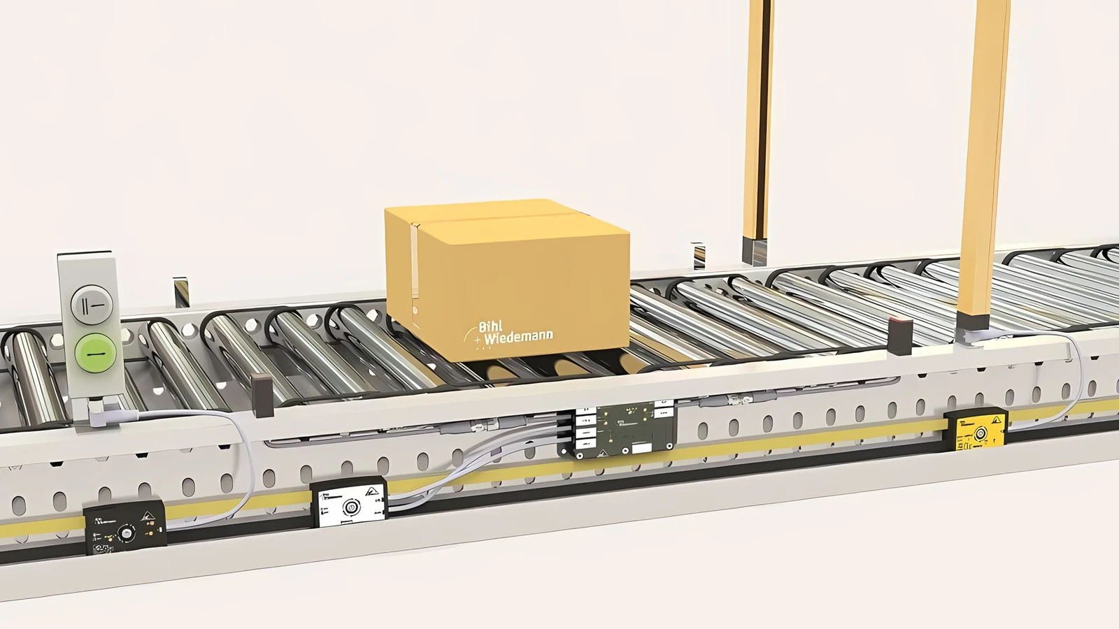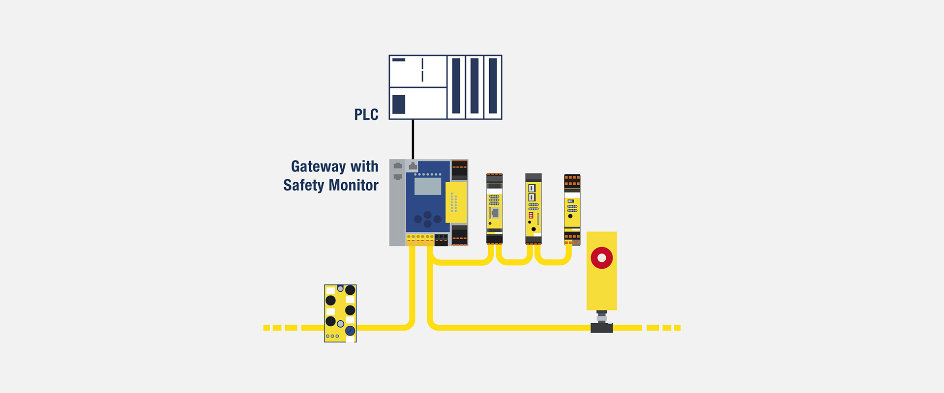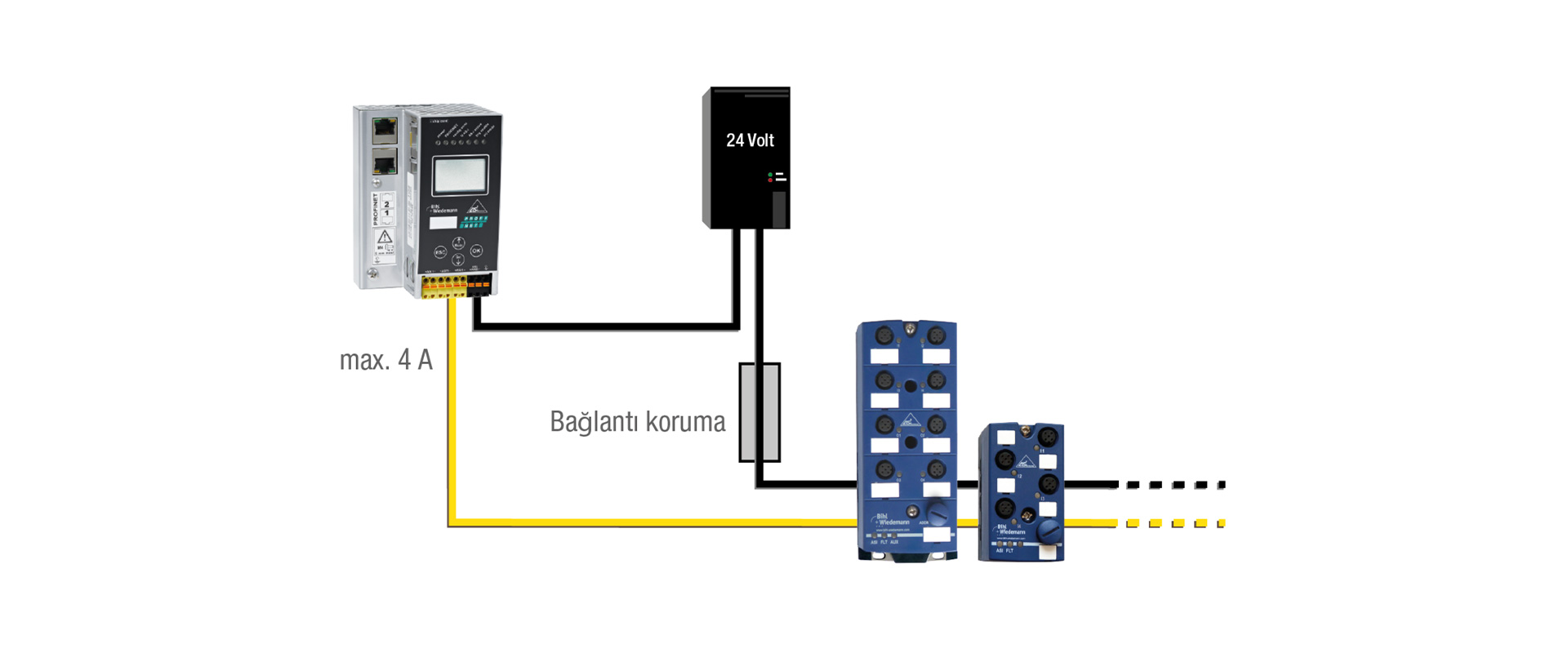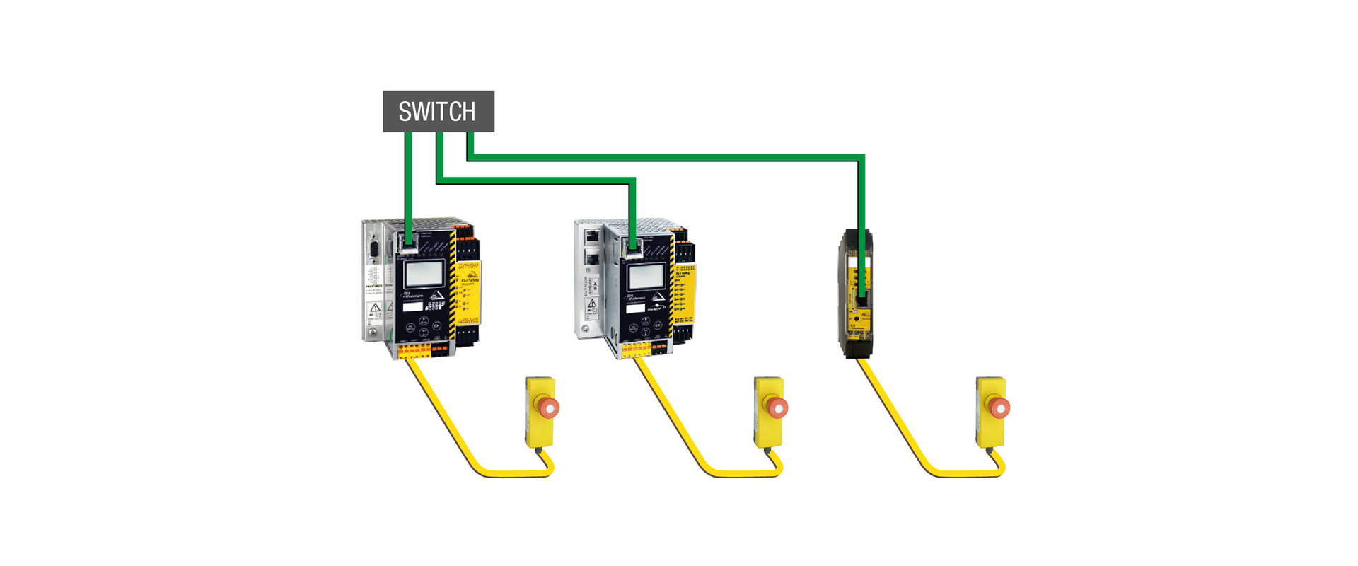
During installation, configuration, fault diagnosis, or cleaning, it may not always be possible to maintain all the protective measures associated with the machine’s normal operating mode. Instead of allowing uncontrolled “bypassing” of these measures in such special circumstances, the Safe Mode Selection function manages these situations through a defined process, specifying who can select which operating mode, how the selection is confirmed, and which safety functions remain active in each mode. Bihl+Wiedemann’s Mode of Safe Operation solution enables preliminary selection via a standard HMI, restricts access using an electronic key system, and ensures that the actual activation is performed in a safe manner by the Safety Monitor. This approach does not replace risk assessments or machine-specific verification procedures.
What does safe operating mode selection address?
In automated production, door locks, light curtains, and fixed protective devices separate the operator from potentially dangerous movements. During setup, it may be necessary for the operator to see the workpiece, tools, or moving mechanisms. Opening the door and bypassing a sensor may seem quick and convenient, but it can blur the machine’s safety conditions, turning a temporary solution into a permanent risk. Safe mode selection defines alternative operating conditions at the design stage and ensures that they can only be activated with authorized safety functions.
A “mode” refers not only to the recipe that changes within the HMI. When the mode is changed, the permitted automatic start, movement speed, direction, axis, or area of operation; the active protective devices; the requirements for operating with manual intervention or approval devices; as well as the reset and restart behaviors may all change. The safety functions associated with each mode must be specified in separate sections. If a function is disabled, it must be clearly indicated which risk-reducing measures have been implemented in its place. A “service mode” in which all protections are turned off in pursuit of production objectives does not qualify as a safe mode selection.
| Design question | Safe approach | Assumption to avoid |
|---|---|---|
| Where is the selection made? | The HMI pre-selection is displayed to the user; the Safety Monitor verifies and activates the selected settings. | Assuming an HMI bit alone is a safety command |
| Who can change the mode? | Authorization levels are restricted through an electronic key or equivalent management | Anyone who knows the password can handle the same risks. |
| What happens if the level of protection is reduced? | Safety measures such as reduced speed, stop, direction adjustment, or approval devices are activated. | Since the maintenance time is short, the risk is considered acceptable. |
| Are there multiple sections? | The mode, boundaries, and interaction with adjacent areas of each respective section are independently defined. | All lines must use the same mode simultaneously. |
| What happens when energy or communication is restored? | The valid authorization and secure selection process are re-verified to prevent unexpected startups. | Assuming the last mode can resume automatically |
The selection chain for a Bihl+Wiedemann solution
The official “Safe Mode Selection” page describes a process in which, on a standard touch panel, the user is presented with only those modes that can be activated using their current permissions. When the user selects a mode, this initial step constitutes a preliminary selection. The Safety Monitor verifies this preliminary selection and displays the confirmed result to the user again. Only with the user’s second confirmation is the corresponding mode actually activated in a safe and secure manner. This feedback process prevents an unintended screen touch or a data mismatch between the HMI and monitor from being accepted directly as a valid safety selection.
Bihl+Wiedemann states that, thanks to the TÜV-certified function blocks within ASIMON360, five different operating modes can be independently configured for up to six individual machine components, and this solution can be applied even in PL e applications. These modes and their levels are inherent features of the solution; it is not mandatory to use all five modes in each machine, and the use of PL e is not automatic either. The selected variant of the Safety Monitor, together with HMI communication, authorization functions, safety features, field devices, and the output circuitry, is thoroughly verified before implementation.
Authorisation and safe selection are different
An electronic key system assigns mode access to user groups such as maintenance technicians, setters and production operators. Bihl+Wiedemann describes five key authorization levels through the Euchner EKS electronic key system. Authorization permits a user to select a mode; Safety Monitor logic processes that selection safely. These are separate functions.
The sharing of keys, their loss, failure to remove them at the end of a shift, or the failure to update the system when a user’s role changes all constitute operational risks. Access matrices should be managed based on user names or roles, and procedures for revoking access and managing backup keys must be established. On the HMI, the currently active user, the selected section, and the active mode should be clearly displayed. Additionally, policies regarding personal data, user registration, and remote access must be implemented in accordance with the organization’s cybersecurity guidelines.
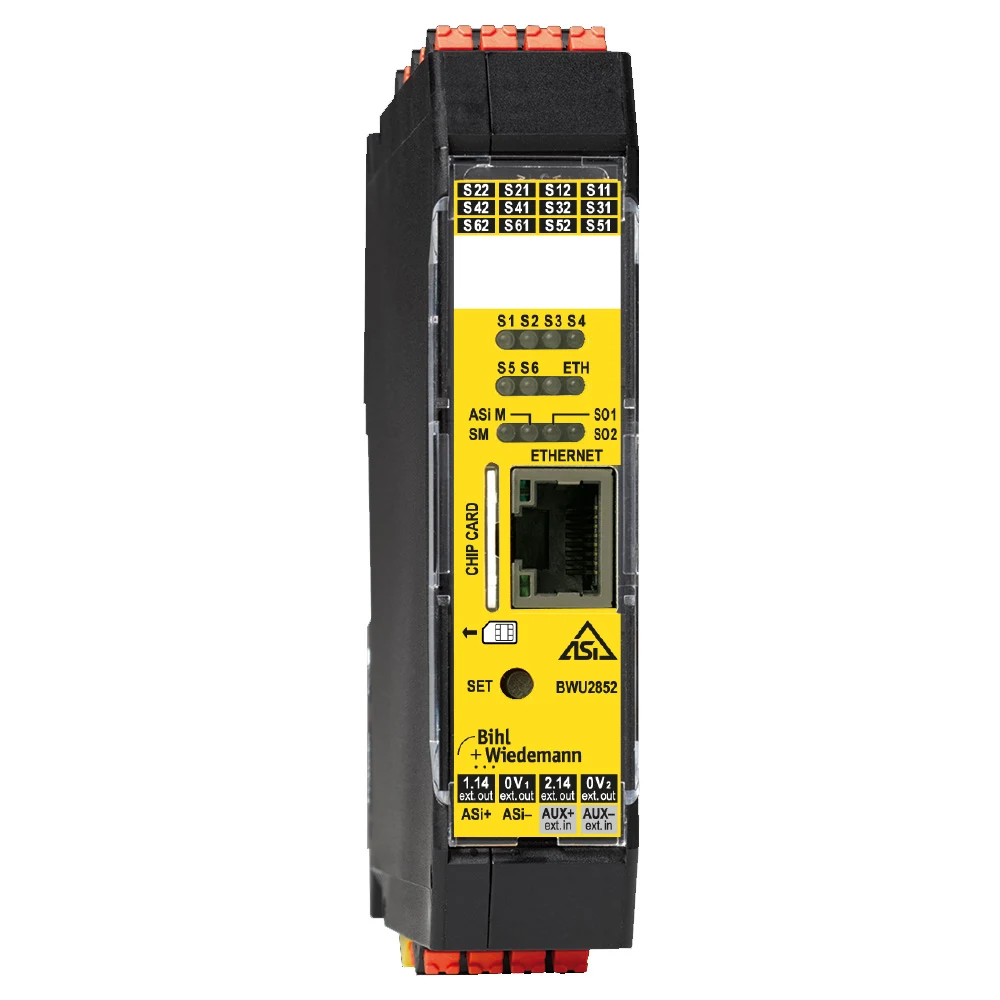
Local safety and speed monitoring: BWU2852
The BWU2852 is an Extended Function Safety Basic Monitor. Its official product page describes it as a compact controller that features local safety inputs and outputs, Safe Link functionality, an Ethernet diagnostic interface, and the ability to monitor stop and running speeds via proximity sensor signals. This combination of features can be utilized for machine-specific applications, such as monitoring only the permitted low speed when the door is open during setup mode. The specific inputs that can be used for speed monitoring, as well as the number of axes and frequency limits, must be selected from the complete product documentation.
Safely reduced speed is more than a low standard drive setpoint. Measure motion independently or through a suitable safety architecture, switch off the safety output within the specified time if the limit is exceeded, and verify an acceptable mechanical stopping distance. Calculate sensor count, channel architecture, gear ratio, pulse frequency and common-cause failure measures. BWU2852 is listed for applications up to Category 4/PL e/SIL 3; the achieved result depends on the selected speed-monitoring architecture and complete safety chain.
How should motion permission work during mode changes?
When setup mode is preselected, the Safety Monitor may evaluate authorization, confirmed selection, guard status, the enabling device and speed-monitoring readiness together. Machine-specific logic can prevent guard unlocking until safely reduced speed is verified, or switch off the safety output if the speed limit is exceeded. An active mode must not itself command motion; standard controls and additional enabling conditions remain separate.
When the mode reverts to production, it must be confirmed that all protective devices are reactivated, doors are closed and locked, and that temporary tools or personnel are no longer in the hazardous area. User confirmation can be one of the conditions required for resetting the system; however, the reset function must not automatically initiate any hazardous actions. This behavior must be clearly specified in the HMI documentation and operator instructions.
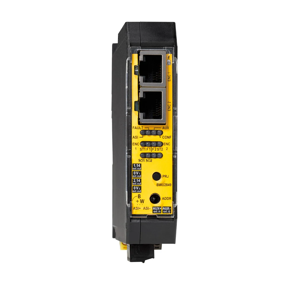
Safe speed and position monitoring with encoders: BWU2849
In some machines, a simple approach may not be sufficient to monitor sensor signals accurately, particularly regarding speed limits or position data with required resolution. The BWU2849 is described in official product documentation as a modular ASi Speed Monitor that supports sin/cos, TTL, and SSI encoder signals. It features two fast electronic safety output circuits and two RJ45 connectors for encoder connections; with the appropriate configuration of sin/cos or TTL signals, it can monitor up to two axes. The manufacturer’s data sheet indicates that when used in safety applications, SSI requires the use of a second encoder as a reference signal; in such cases, the two encoder ports can be used for monitoring a single safety axis. The specific signal types supported, encoder power requirements, adapter cables, and the method of connecting these signals to the control drive must be confirmed in accordance with the complete product instructions.
With the safe mode selection, conditions such as the position range, direction, stop position, or low speed can be defined. For example, manual operation may be permitted only within a specific mechanical area and at reduced speeds. However, this example does not imply that the BWU2849 can perform all these functions independently on every machine. The safe operation features are determined based on the selected encoder architecture, drive behavior, monitor configuration, and the influence of the safe outputs on the actuators.
Central selection for machines with multiple sections: BWU3961
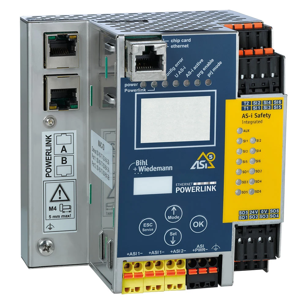
The BWU3961 is a gateway model that includes two ASi-5/ASi-3 masters, a POWERLINK interface, and an integrated ASi-5/ASi-3 Safety Monitor. Its official data sheet lists the following features: Mode of Safe Operation support, Safe Link functionality, six single-channel or three dual-channel safe inputs depending on the configuration, six electronic safe outputs, an OPC UA server, a REST API, and web-based diagnostic tools. Such a gateway can be utilized to enable safe operation functions while displaying the HMI mode selection settings to the higher-level control system, and to integrate the safety-related functions within the same monitor.
Two ASi networks can help organize field devices into physical and logical groups on machines that are long or have been divided into sections. Bihl+Wiedemann’s solution supports up to six independent mode selection options; whether one section can operate in production mode while another cannot is again determined through risk assessment. If there is coordinated movement in the transfer zone, material dropping, jamming, or access by adjacent robots, the sections cannot be considered completely independent. In such cases, Safe Link or local safety signals must be used to establish the necessary mutual authorization.
The role of a standard HMI in a safety system
The solution allows the use of a standard HMI; its advantage lies in the ability to clearly display the machine configuration, section names, and the current operating mode to the operator. The HMI lists the modes that can be selected with the current permissions, provides a preliminary selection, and then reverts to displaying the mode confirmed by the Safety Monitor. Since the safe activation process takes place on the monitor itself, the HMI panel is not considered a safety controller.
In interface design, clear and explicit language should be used instead of similar names and colors. Instead of vague titles like “Manual 1” and “Manual 2”, purpose-based descriptions such as “Mold Setting – Low Speed” or “Cleaning – Movement Prohibited” should be preferred. The active mode, the selected section, and any remaining protective settings must be continuously visible. If the pre-selection on the touchscreen differs from the actual active mode, the user must be able to distinguish between the two clearly.
Function blocks and version management in ASIMON360
The “Mode of Safe Operation” function is enabled in ASIMON360 configurations; the available modes are assigned to specific permission levels and are utilized within the relevant MSO blocks for safety-related logic. According to the official documentation, up to five modes and six individual examples can be freely configured. For each mode, it is necessary to verify that the block connections, active safety functions, and outputs meet the required specifications. Changing the name of a copied example does not guarantee that the safety-related connections have been correctly modified.
The configuration file, device software, HMI screen, and user permission settings must all be part of the same modification package. If the name of a mode is changed on the HMI while its safety logic remains unchanged, it may lead to serious operational errors. The checksum of the approved version, the device’s backup settings, and the restoration procedures must all be properly documented. After any modifications, not only should the new HMI screen be tested, but all affected mode transitions must also be verified thoroughly.
Transition states matter as much as the modes themselves
Transitions from production to setup, setup to maintenance or a regional mode to an overall stop must not leave the system briefly undefined. The previous mode’s safety conditions remain active during preselection; the new mode becomes active only after Safety Monitor verification and user confirmation. Cancel preselection after timeout, contradictory requests or communication loss, and retain the defined safe state.
Whether the active mode can be immediately terminated upon removing the electronic switch depends on the specific application. While immediate termination may cause some machines to stop safely, in other processes it could pose additional risks. Similarly, restoring power may not result in the system returning to its previous state as stored in memory. The appropriate behavior is determined through risk analysis, operational procedures, and configurations permitted by the manufacturer’s specifications; the test results are then used to inform operator training.
Fault scenarios for FAT and SAT
- Unauthorized selection: It is confirmed that prohibited modes are not displayed or enabled when the permission level is insufficient.
- Wrong section: It is observed that the selection made for one section does not cause any unexpected changes to the safety functions in adjacent sections.
- Loss of pre-selection: The HMI communication is interrupted between the preliminary selection and confirmation steps; the system must remain in its previous safe state.
- Speed overrun: In the adjustment mode, the safely specified speed limit is deliberately exceeded, and the safe output response is measured.
- Sensor error: The expected safe behavior is verified in the event of a fault in the encoder channel, the initiator, the door lock, or the authorization device.
- Loss of authorization: Electronic key removal procedures are performed, along with tests for invalid keys and cancelled user scenarios.
- Energy recovery: It is verified that no automatic actions are triggered when the HMI, gateway, Safety Monitor, and field modules are opened in different sequences.
- Version mismatch: Different combinations of HMI and safety configuration settings can be detected, or such combinations may be prevented during the commissioning process.
Project and quotation checklist
- Each operating mode’s purpose, permitted motion, active safeguards and prohibited actions
- Required PLr/SIL targets, safe state, response time and compensating measures for each mode
- Machine sections, common hazards, transfer points, and safe access between areas.
- HMI pre-selection process, validation feedback, two-stage approval, and timeout behavior.
- User roles, electronic key levels, procedures for loss/revocation, and event logging.
- Safety Monitor or gateway – full product code; ASi networks, Safe Link, and higher-level fieldbus interfaces.
- Sensors or encoders are used to determine safe speed, stop position, and location; mechanical ratios, resolution, and error response also play a crucial role in this context.
- Version compatibility, backup, and authorized change management among ASIMON360, HMI, and PLC projects.
- FAT/SAT fault injection, measured stopping times, operator training and periodic tests
The purpose of selecting a safe mode is not to make maintenance activities more difficult, but rather to make non-production operations visible and controllable. Bihl+Wiedemann’s solution combines a standard HMI, authorization mechanisms, a Safety Monitor, and – when necessary – safety motion monitoring within the same architectural framework. However, true safety can only be ensured through a machine-specific mode matrix, as well as thorough validation that includes the right product variants and transition states.