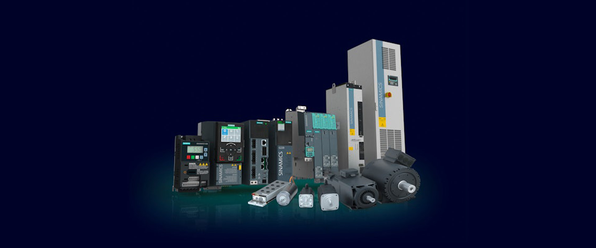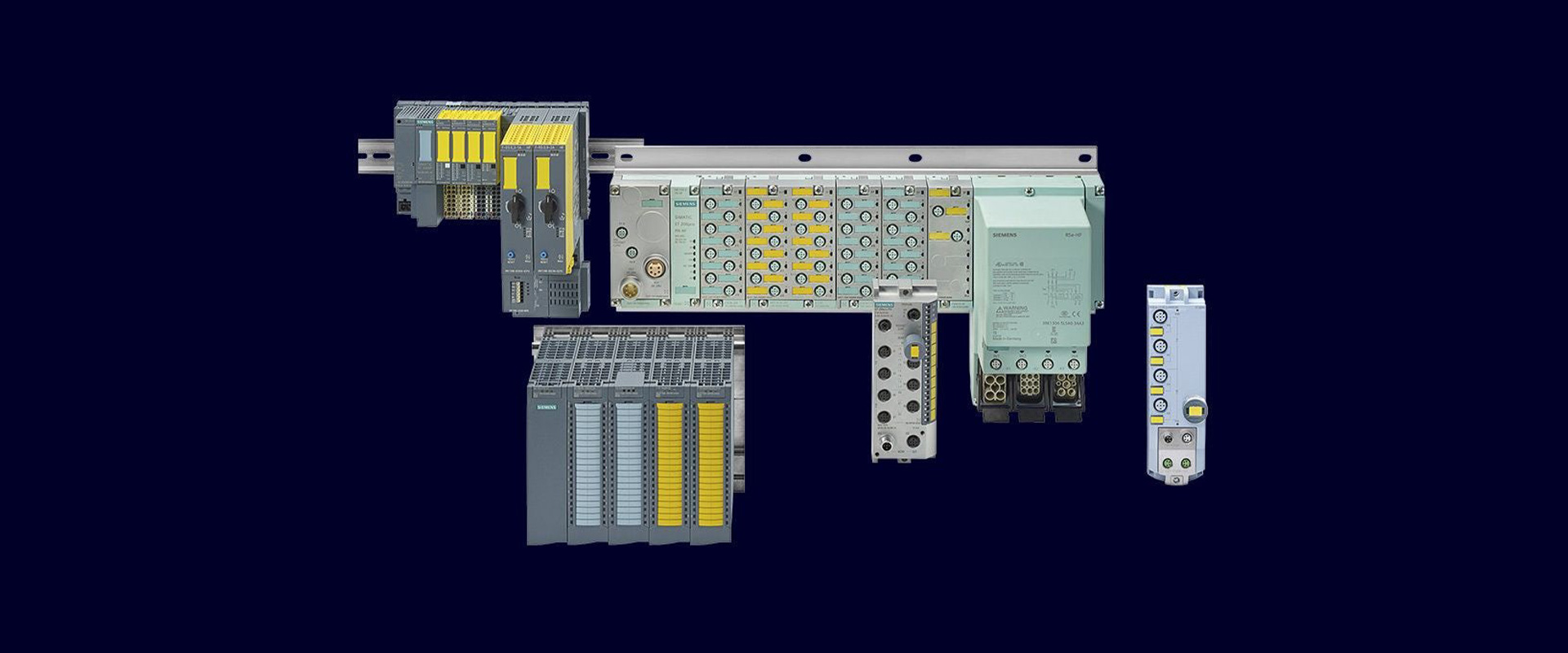
The Safety Specialist approach treats machine safety as an engineering discipline managed throughout the lifecycle, rather than defining it through a relay, a safety PLC or a certificate obtained after an examination. Siemens' current SITRAIN functional safety training and examinations conducted with TÜV cover risk assessment, safety function requirements, EN ISO 13849-1 and IEC 62061, verification, validation, changes and documentation. Successful completion provides evidence of personal competence; it does not by itself demonstrate that a particular machine, project or Siemens product is safe. A safe outcome depends on correct risk analysis, component selection, calculations, implementation and site acceptance testing as well as a competent team.
What does TÜV-certified safety expertise mean?
The program names and requirements listed on Siemens’ official SITRAIN pages may vary depending on the country. In the United Kingdom, the current Machine Industry page lists the “Functional Safety for the Machine Industry Workshop & Certification” program under the code ST-NSST. In the Netherlands, the detailed program description mentions the issuance of a personal TÜV certificate upon completion of the examination, within the framework of TÜV SÜD and “Siemens Functional Safety Professional.” Therefore, it is important not to use vague phrases such as “TÜV-certified system” in offers or resumes; instead, the specific details of the certificate—including its name, scope, issuing organization, number, and validity requirements—must be clearly stated and verified in the relevant documentation.
An important benefit of training is methodological knowledge before product use. Siemens' course descriptions cover legislation and standards, risk assessment, safety requirements specifications, architectures, reliability parameters, software, verification and validation. These extend beyond a product selection list. Instead of copying a circuit, a specialist examines how hazardous motion arises, which event requires which safe state, and what evidence demonstrates that the design achieves it.
| Stage | The specialist's main question | Expected project record |
|---|---|---|
| Risk assessment | Who may be exposed to which hazard during intended use or misuse? | Machine limitations, tasks, hazard list, initial risk level, and risk mitigation measures |
| Requirements | When should the function be triggered? What constitutes a safe condition, and how quickly must it be achieved? | Safety requirement specification, PLr or SIL target, response time budget |
| Design | Is the entire chain, from sensor to actuator, suitable for the desired application? | Architecture, schematic diagrams, calculations, device variants, error responses, and software design. |
| Verification | Do the design and calculations meet the written requirements? | Independent testing, calculation results, code review, and traceability matrix. |
| Validation | Does the actual machine exhibit the correct safe behavior under all anticipated conditions? | FAT/SAT scenarios, measurements, error injection, deviation records, and closure records. |
From risk assessment to a safety function
The process begins not with a hardware catalog but with defining the limitations of the machine itself. Normal production operations, as well as procedures for adjustment, cleaning, fault repair, maintenance, power shutdown, and anticipated misuses, are all examined separately. Hazards such as cutting, crushing, squeezing, flying debris, electrical shock, pressure, heat, and unexpected movements are recorded, along with the ways in which individuals may be exposed to them. Structurally safe design and mechanical safeguards are of primary importance. Safety functions based on control systems are merely part of a comprehensive risk mitigation strategy; they cannot replace proper protective measures or safe operating procedures.
A clear sentence for each function strengthens the design: for example, 'When the guard door opens, hazardous drive energy will be removed within the specified time, and closing the door will not cause an automatic restart.' Then define the input device, logic, safe communication, output and power element. Required performance level PLr under EN ISO 13849-1 and the required SIL target under IEC 62061 derive from risk assessment. Neither is automatically achieved by the highest rating printed on a component. Assess category or architecture, probability of dangerous failure, diagnostic coverage, common-cause failures, duty cycle and software measures for the complete function.
Why are response time and stopping distance separate evidence?
The proper functioning of electrical logic alone does not guarantee that dangerous movements are stopped in a timely manner. The total response time consists of the sensor’s detection time, the safe input and control cycle, the network update time, the safe output time, the behavior of the contactor or drive, as well as the mechanical deceleration process. When installing light curtains or area sensors, the measured stopping time should be taken into account, in accordance with relevant standards. If the machine load, speed, brake wear, or the product recipe change, the previously calculated distances must be reevaluated.
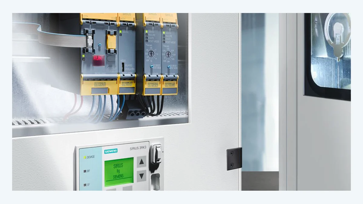
SIRIUS 3SK safety relays for compact functions
The SIRIUS 3SK series offers modular solutions for evaluating sensors and managing safe shutdown processes in machine safety applications such as emergency stop and protective door monitoring. Siemens’ latest product page positions the 3SK1 series for more basic applications, while the 3SK2 series, which can be parameterized via software, is designed to meet more complex requirements. The ability to individually disable the safe outputs of the 3SK2 series, along with its input/output expansion options and diagnostic data transmission capabilities to higher-level control systems, make it an alternative to wired multi-relay systems in compact machinery.
The product-page statement 'up to SIL 3 and PL e' describes the upper application scope achievable with suitable variants and architecture. For a selected 3SK, check the exact order number, input type, output technology, expansion connection, feedback monitoring, reset behaviour, supply and environmental conditions in its documentation. Include contactor weld monitoring, short-circuit and cross-circuit diagnostics, cable routing and common-cause failure measures in the function assessment. A status bit sent to a standard PLC is diagnostic information; it is not a safety control signal without an appropriate safe architecture.
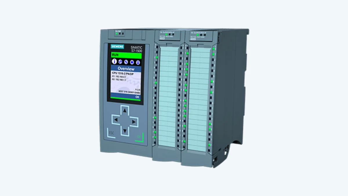
Programmable, scalable safety: SIMATIC F-CPUs
Consider fail-safe SIMATIC controllers as the number of functions, safe data exchange between cells or diagnostic requirements grows. Siemens' current SIMATIC Controller Selection Guide includes fail-safe capability as a selection dimension. S7-1500 F-CPU documentation describes processing standard and safety programs on the same CPU, with fail-safe communication and distributed architectures. This makes standard automation and safety engineering visible within a common toolchain; the safety program still requires its own authorisation, signature, compilation records and acceptance process.
CPU performance is not selected by program line count alone. Consider the safety cycle time, total F-I/O, PROFIsafe connections, motion or technology tasks, network topology, memory, spare parts standard and future expansion together. Divide safety program blocks into clear functions, with explicit reset, reintegration, transition mode, maintenance permission and restart conditions. A software change requires more than testing the changed rung; use impact analysis to define regression tests for the affected functions.
The distributed signal layer: SIMATIC ET 200SP fail-safe I/O
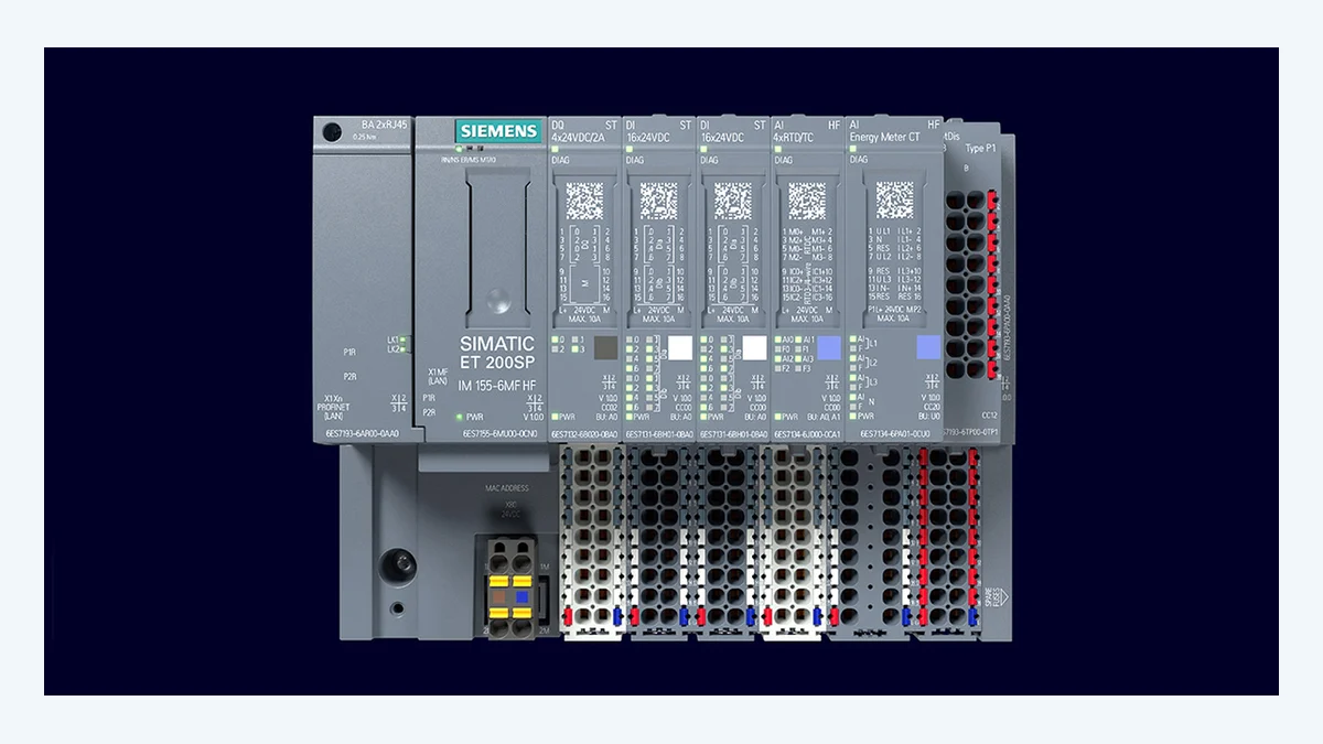
Distributed I/O near the field or production cell can simplify wiring and diagnostics compared with long safety-sensor cables to a central panel. Siemens' current ET 200SP page describes standard, analogue, technology and fail-safe I/O modules within the same station family. The system manual explains PROFIsafe communication between the F-CPU and fail-safe modules. Combining standard and F modules in a station does not change each channel's safety capability: safety sensors require the correct F inputs, and safety outputs require appropriate F output modules and validated circuits.
Include network loss, module removal, channel faults and power restoration in the distributed architecture's test plan. Changing an F-parameter address, device name or hardware configuration is a controlled safety change. Hot swapping and automatic reparameterisation do not remove the need for functional testing. After replacement, verify the module, channel mapping, F parameters and response of the final switching element.
Distinguish verification from validation
Verification examines whether the solution follows written requirements and design rules. It covers schematic checks, reliability calculations, conformity documents, program review, timing calculations and traceability. Validation tests whether the completed machine behaves correctly in its intended use. Physically trigger each emergency stop, guard door, two-hand control, light curtain, safe-speed or torque-off function, observing outputs and hazardous motion. Introduce foreseeable single-channel faults, cross-circuits, welded contactors, network loss and power restoration through feasible, safe test methods.
Independent review is particularly important for high-risk or complex functions. A designer's own checks are valuable, but the project organisation must define acceptance responsibilities, authority and the required degree of independence. A TÜV-certified specialist can support review quality; the evidence nevertheless comes from recorded test results rather than a person's title. Record instrument calibration, test conditions, acceptance criteria, measured values, nonconformities and corrections in the same protocol.
Selection checklist for purchasing and project start-up
- Have the machine limitations, user tasks, maintenance procedures, and potential misuses been clearly defined?
- Are the safe state, PLr/SIL target and maximum response time specified for every safety function?
- Has the selected order variant of SIRIUS 3SK, SIMATIC F-CPU, or ET 200SP F-I/O been verified against the current documentation?
- Has the entire system been thoroughly designed, including sensors, logic circuits, the network, output components, and mechanical stop mechanisms?
- Have the reset and restart functions, as well as the field of vision, accessibility, and the risk of unexpected movements, been thoroughly evaluated?
- Are standard data and safety-related data clearly distinguished on diagnostic screens and in PLC tags?
- Have the procedures for software authorization, version control, signing, backup, and change management been defined?
- Have FAT, SAT, stopping-time measurements, fault injection and periodic proof tests been planned?
- Has the name, scope, issuing organization, and current validity period of the specialist certificate been verified on the document itself?
Maintaining expertise during operation
A safety project does not end with the issuance of an approval document. Changes such as disabling protective devices, bypassing faulty sensors, adjusting recipe settings to increase speed, granting new robot access, or modifying the load can all disrupt the initial risk assessment. The maintenance team should be provided not only with the diagnostic code but also with safe intervention procedures and a test checklist to address the issue. The frequency of periodic tests is determined based on the component manual, reliability calculations, usage frequency, and facility procedures. If failed tests or repeated bypassing incidents are recorded, the risk assessment and availability design should be re-examined, rather than simply replacing the equipment.
Competence is also a dynamic system that requires monitoring of standard revisions, software and hardware updates, new threats, and organizational role changes. In cases where there is a certification validity period or renewal requirements, the current rules established by the certification authority must be followed. It is essential that the person assigned to a project possesses not only the necessary training but also relevant practical experience, product knowledge, and a clear understanding of the scope of their responsibilities. In this way, the term “certified expert” ceases to be merely a marketing label; it becomes a working approach in which decisions are based on verifiable evidence and the actual behavior of the machinery is monitored accordingly.
The Siemens Solution Partner programme also makes partners' expertise in particular technologies visible through training and certification. Company-level partner or expertise records and the actual designer's TÜV certificate are different evidence. During purchasing, verify current partner status through Siemens' official partner channel and the assigned person's certificate through its stated scope and validity, separately.