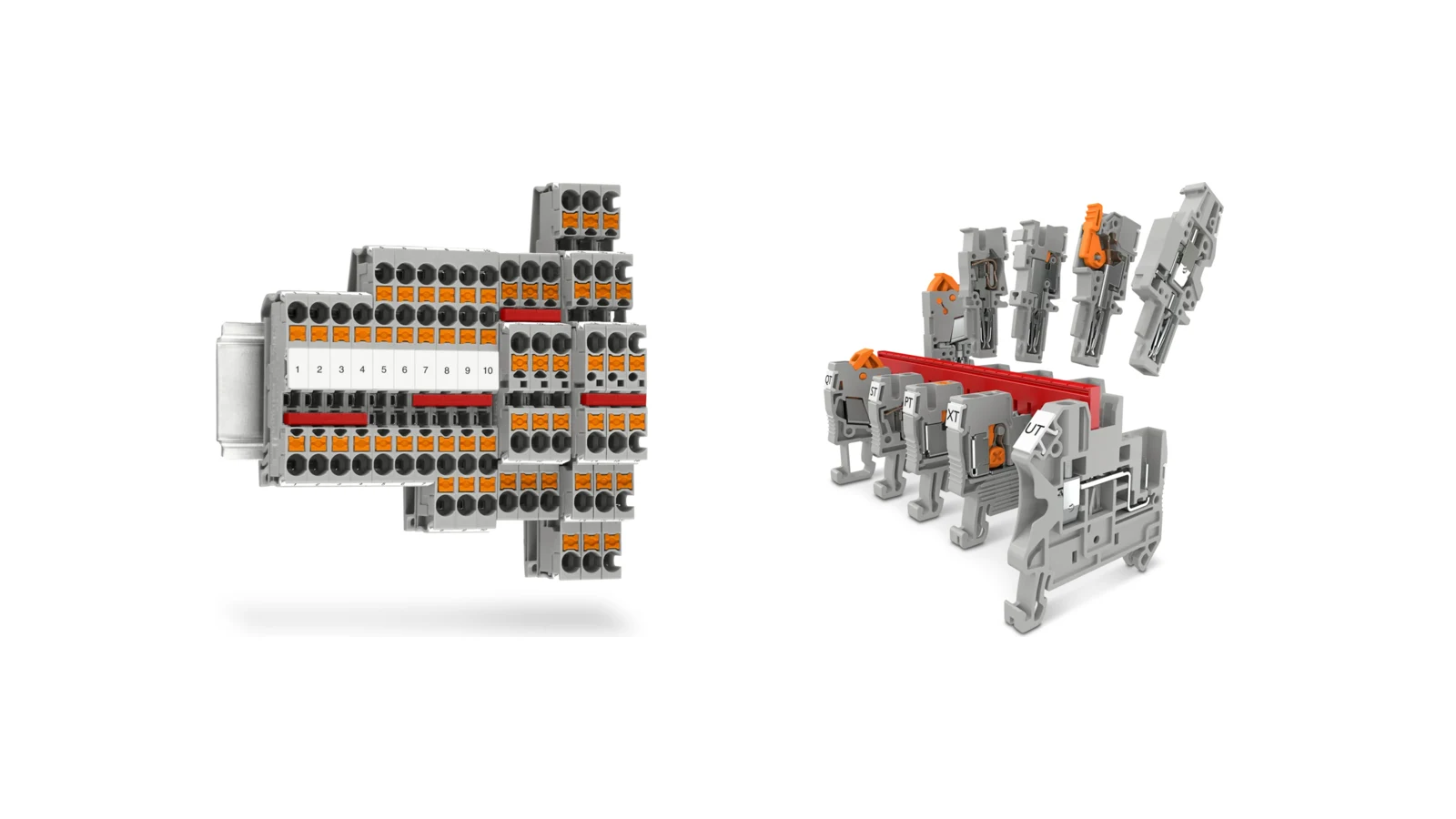
A series of DIN-rail terminal blocks in a control panel serves as the physical interface between conductors from the field and power distribution, control, and measurement circuits. If these components are merely viewed as “gray blocks used to connect cables,” issues such as mismatched cross-sections, limited testing possibilities, unnecessary panel space consumption, and potential voltage conflicts during maintenance can arise. Phoenix Contact’s range of DIN-rail terminal blocks enables the integration of various functions—such as feed-through terminals, multi-conductor units, multi-level designs, isolation components, fused connectors, sensor/actuator interfaces, high-current devices, transformers, and plug-in connectors—within a unified system approach. This allows for selections to be based not only on connection technology but also on the specific functionality of the circuit.
This catalog guide places Phoenix Contact product families within the context of a proposal and design process. First, the electrical function of the circuit and the conductors to be used must be defined; subsequently, the connection technology, nominal cross-section, actual connection range, current and voltage ratings, number of layers, bridging options, testing requirements, marking specifications, and DIN rail mounting requirements must be determined. The values provided here represent manufacturer-supplied data that assist in understanding the product family. For the final product code, it is necessary to verify these values in conjunction with the IEC/UL data from the current technical specifications, as well as the environmental and installation conditions and applicable standards of the project.
Start terminal block selection with the circuit function, before the product code
A feed-through terminal block establishes a reliable connection between two conductors. When it is necessary to distribute the same potential across multiple wires, a multi-conductor design can be used. If DIN-rail width is limited but sufficient cabinet height is available, a multi-leveled configuration may be appropriate. While multi-level connectors offer more space, it is essential that the layers are clearly marked and that tools can easily access each connection point. Therefore, the final dimensions of the complete assembly—including the connector width, bridge pieces, labels, spacer plates, and the space required for cable routing—should be carefully calculated, rather than relying solely on the connector’s specifications listed in the catalog.
Disconnect and knife-disconnect terminal blocks are used to divide a circuit at the wiring level, creating accessible points for measurement and maintenance. Phoenix Contact emphasizes the visibility of the separation point in knife-disconnect terminals, as well as the ability to integrate functions such as fuses or component sockets in basic separation terminals. Fused, diode-equipped, and component terminals also extend these additional functions to the circuit rail level. However, the type of fuse, power loss characteristics, polarity, and replacement procedures must be determined based on the specific component being used; the functions provided by the terminal should not replace the circuit’s built-in protection measures.
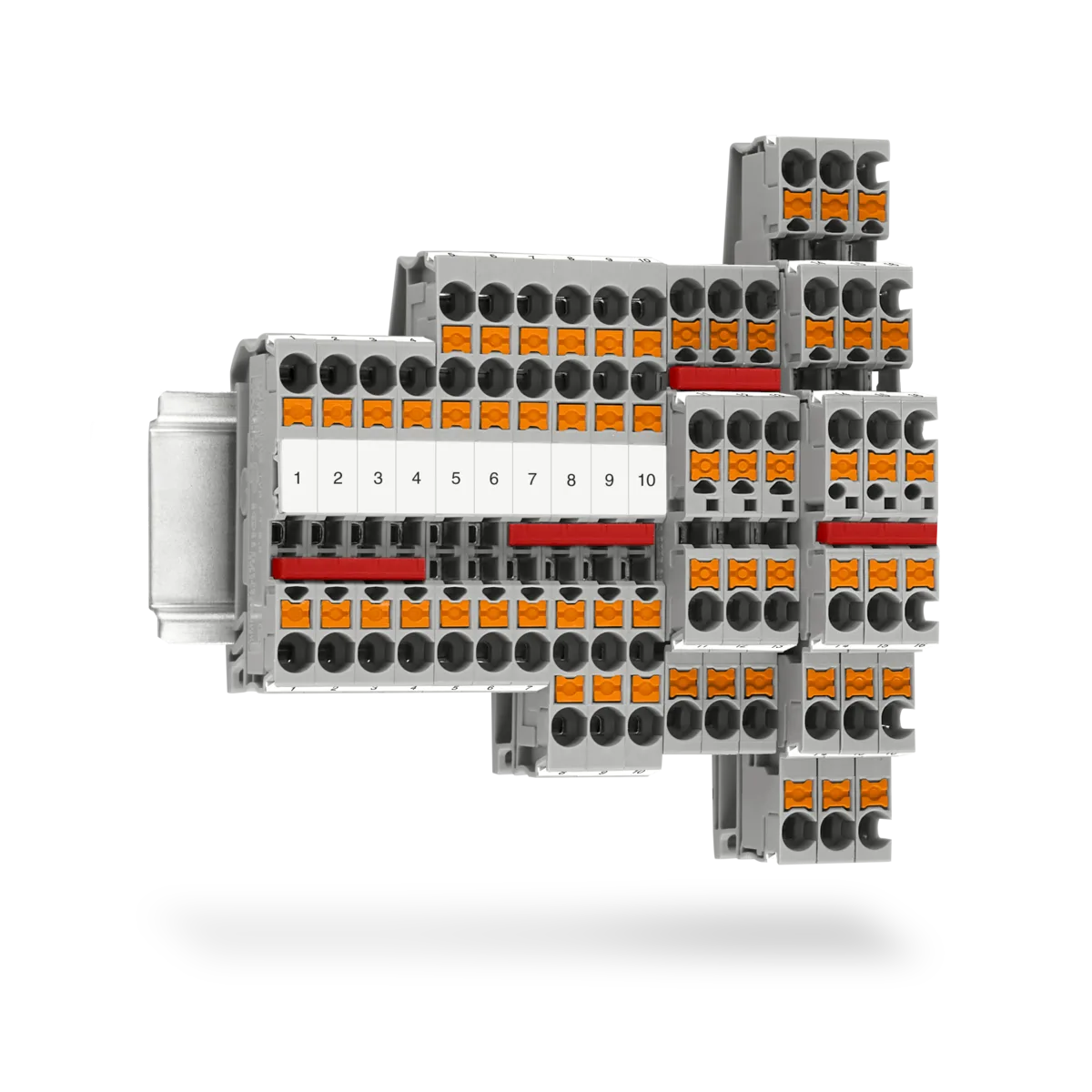
Key differences between Push-X, Push-in and screw connections
In Push-X technology, the contact spring is mechanically preloaded at the factory. Solid and stranded conductors can be inserted directly, with or without ferrules; the conductor triggers the mechanism at the end of the connection chamber, releasing the spring to clamp it. Pressing the orange button releases the conductor and reloads the spring. Push-in technology permits direct, tool-free connection of solid conductors and ferruled stranded conductors. Fine-stranded conductors without ferrules require use of the operating button and the installation method specified for the product.
Screw connection is a widely accepted method that provides high contact quality and strong gripping force. Service requirements, type of conductor, and industry standards may determine the preference for this connection method; however, it is essential to apply the prescribed torque value using the appropriate tool. Spring-loaded, quick-connect, and bolted products also offer distinct advantages depending on the application. Rather than choosing a connection technology based on a single criterion such as “state-of-the-art” or “most robust,” it is more appropriate to compare factors such as conductor preparation method, number of assembly steps, vibration levels, automation degree, maintenance requirements, and verifiable quality control measures.
Phoenix Contact’s terminal-block page gives a 4 mm² nominal Push-X feed-through terminal as an example, with a 0.5–6 mm² connection range, 32 A nominal current, and 500 V nominal voltage. The new 1.5 mm² nominal family on the same page lists 0.34–2.5 mm², 17.5 A, and 500 V. These values must not be generalized to all XT products. Where connection count, color, approvals, cross-section, or function differs, consult the data sheet for the selected order code.
CLIPLINE complete: design terminal blocks together with their accessories
A key aspect of the CLIPLINE complete approach is that it transforms a series of terminals into something that encompasses not only individual components but also functions such as bridging, labeling, and testing. The manufacturer states that, thanks to its dual-function channels, it is possible to flexibly combine terminals with different connection methods while using standardized accessories. In such a system, bridging components distribute common voltages; testing accessories facilitate measurement; and labeling areas ensure clear correspondence between the schematic diagram and the actual components in the field.
The fact that accessories are compatible does not mean that every accessory automatically fits every terminal block. The number of pins, the need for cutting or skipping connections, and the allowable current capacity must be determined based on the selected terminal block family. Mechanical components such as end caps, partition plates, and track stoppers are also part of the complete assembly. When different voltage levels or circuit classes are used in the same system, the required clearance, separation measures, and protection against electric shock must be assessed in accordance with project specifications. The complete assembly’s product data sheet should list not only the terminal blocks but also all these components.
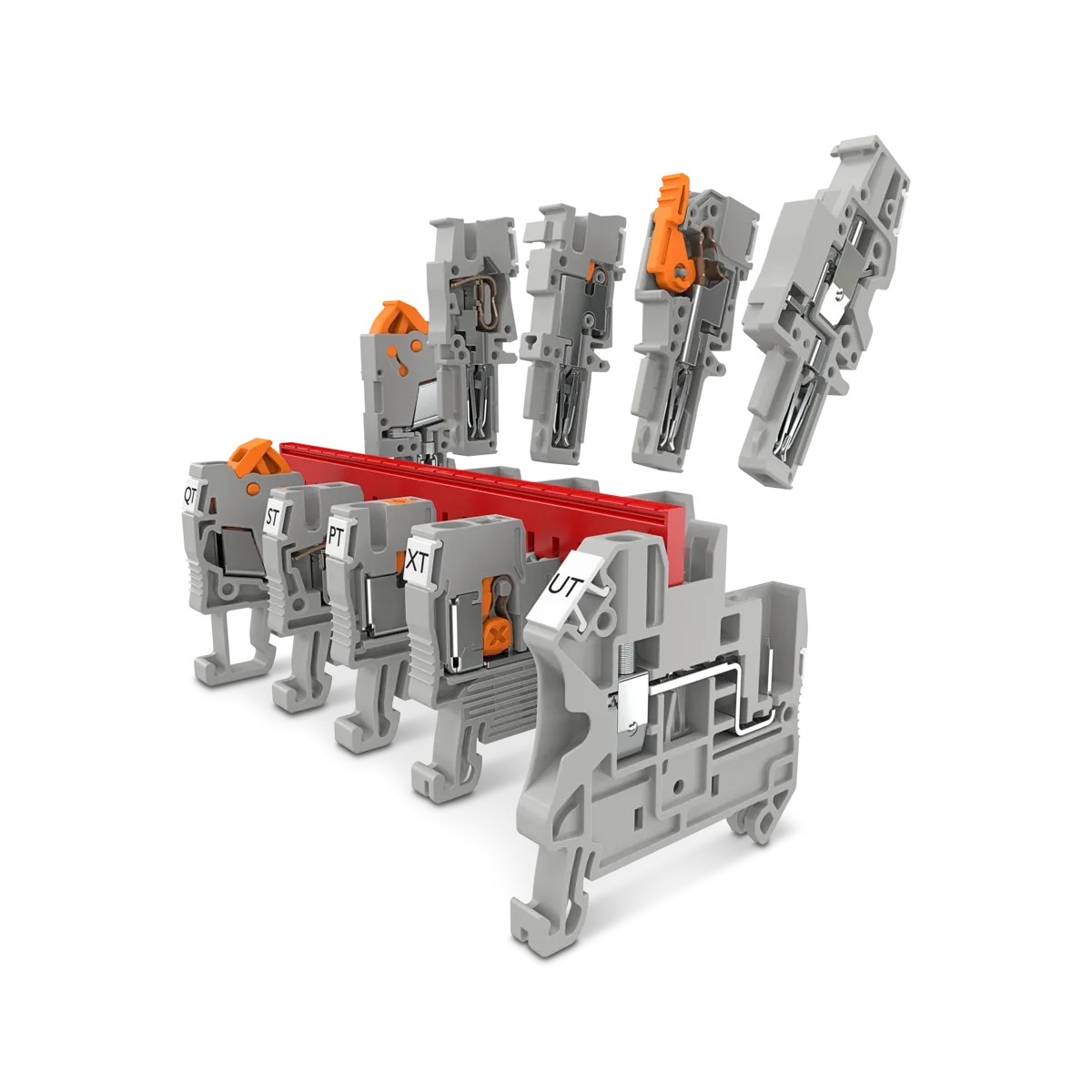
When should function terminal blocks be considered?
Sensor and actuator terminals provide a compact way to integrate signal and power connections. The Phoenix Contact website offers options that support sensors with two, three, or four conductors, and some versions include LED indicators for status indication. It is important to verify the effects of the circuit voltage, polarity, and leakage current on these LEDs. In projects where numerous signals need to be transmitted between the field devices and the controller, marshalling terminals and marshalling panels can be used to achieve high connection density, clear wiring, and easy identification.
In current and voltage transformer circuits, measuring and disconnecting terminals are designed to integrate connection, disconnection, and testing functions within a unified interface. The operation and maintenance of the secondary circuit of a current transformer require specific procedures; since incorrect operation can lead to hazardous voltages, safe practices cannot be assumed solely based on the product name. The wiring diagram of the selected terminals, the shorting and test sequence, as well as the procedures for connecting test leads and applying locking/marking measures, must all be carefully designed within the context of a competent electrical engineering approach.
High-current terminals represent a separate product category dedicated to the distribution of high power using conductors of large cross-section. The Phoenix Contact general website mentions designs in this category that can handle voltages up to 1,500 V; however, this broad portfolio does not apply to every individual product. The material of the conductor, its cross-section, the type of cable connector or direct connection method, the clamping torque, the maximum temperature rise, and the short-circuit resistance must all be determined based on the specific product code. In the case of miniature and micro terminals, the goal is to provide neat and organized cabling in confined spaces; therefore, compactness must be balanced with the allowable cross-section and accessibility for tools.
| Circuit requirement | Phoenix Contact product family to consider | Key data to verify in the quotation |
|---|---|---|
| Standard connection of two conductors | Feed-through terminal block | Connection technology, cross-sectional range, current, voltage, and rail type |
| High connection density | Multi-conductor or multi-layer terminal blocks | Number of levels/connections, width, marking, and access |
| Isolating the circuit for maintenance and measurement purposes. | Disconnect or knife-disconnect terminal block | Separation components, test accessories, nominal values, and procedures. |
| Adding fuses, diodes, or other components to the circuit. | Fuse, diode, or component terminal block | Component type, power loss, polarity, replacement options, and touch protection features. |
| Pluggable connection for a prewired unit | COMBI plug-in terminal blocks | Number of poles, connector type, locking mechanism, coding system, and current-carrying capacity values |
| Distribution of sensor signals and voltages | Sensor/actuator terminal block | Number of conductors, common terminals, LED version, and label arrangement. |
| Current/voltage transformer measurement circuit | Transformer and test-disconnect terminal blocks | Shorting/test sequence, wiring diagram, and operational safety |
Plug-in COMBI connections and modular machine design
Plug-in terminals enable the connection of pre-installed cable harnesses, which are already fixed in place on the track, to a detachable connector. In Phoenix Contact’s COMBI product range, the opposite side of the plug-in section offers options such as Push-X, Push-in, screw-type, or spring-loaded connections. The Push-X/COMBI example shown on the current page is characterized by a nominal cross-section of 2.5 mm², a connection range of 0.5–4 mm², a current rating of 24 A, and an operating voltage of 800 V. These technical specifications apply to the specific product configuration depicted on the page; they must be confirmed again in accordance with the selected connector and terminal combination.
In modular machine units, a plug-in design can facilitate pre-installation and maintenance. To ensure this, the matching of plugs and sockets must be guaranteed through mechanical coding, the number of poles, and circuit labeling. It is essential to prevent the accidental connection of two connectors that look identical during the design phase; therefore, separation or locking accessories should be selected as part of the product system. Additionally, the vibration levels, insertion and removal cycles, and field accessibility must be verified and compared with the specifications outlined in the current product documentation.
DIN rail and mechanical layout calculations
The selection of DIN-rail terminal blocks is not independent of the mounting rail. It must match the project specifications, whether they refer to NS 35/7.5, NS 35/15, or another type of rail. The height of the connector must allow sufficient clearance for the panel cover, cable channels, and the bending radius of the conductors. The total required length along the rail must include end caps, splices, stoppers, and a sufficient allowance for expansion. To prevent heavy conductors from exerting mechanical stress on the connectors, cable fixing and support points must also be carefully planned.
The terms “protective conductor terminals,” “functional earthing connections,” and “shielding connections” do not refer to the same concept. When considering the protection connections of DIN rails and mounting plates, it is essential to take into account both the approved mounting methods for the terminals and the equipotential bonding design of the entire installation. The surface coating of the rail, the connection points, and the mounting instructions must not be overlooked. Moreover, the color coding should not be merely a matter of aesthetic preference; it must conform to the manufacturer’s standards for PE conductors, neutral conductors, control voltages, and special-purpose conductors.
A digital bill of materials with clipx ENGINEER
Phoenix Contact offers the clipx ENGINEER software for planning terminal strips and the layout of assembled control panels; it also refers to interfaces with ECAD programs. While digital planning does not automatically ensure that product selections are technically correct from an electrical perspective, it is useful for integrating terminal blocks, accessories, labeling elements, and rail components into a single bill of materials. When the device list or I/O configuration in a project is updated, the terminal strip, labels, and material list can all be managed using the same version control mechanism.
Any changes made during production must also be reflected in the digital project. For example, if a bridge is added on-site, a fuse holder is replaced, or the terminals are used in a different color, these modifications should be accurately documented in the subsequent maintenance records. Therefore, the configuration used during the bidding phase, the production approval details, and the final as-built modifications should be considered as separate milestones in the project process.
Terminal block quotation checklist
- Classify the circuits: Categorize power, control, safety systems, analog measurement devices, communication components, transformers, and PE circuits into separate functional groups.
- Define “conductor”: Specify copper or another permitted conductor material, solid/stranded construction, ferrule, nominal cross-section, and actual diameter.
- Verify the electrical load: Compare the operating voltage, continuous current, short-circuit conditions, temperature requirements, and necessary insulation specifications with the product code.
- Choose your connection technology: Match the installation time, preparation methods, service procedures, and quality control approaches with the appropriate mounting methods—such as Push-X, Push-in, threaded connections, or others.
- Add functions: Define disconnect, test, fuse, component, LED, sensor-potential, or plug-in requirements for each circuit.
- Complete the accessories: Include the bridge, label, test lead, end cap, separator, and track stopper in the completed terminal block assembly.
- Check the layout: Calculate the DIN rail type, the internal width of the control panel, the channel spacing, the bending radius, the accessibility for tools, and the required clearance.
- Request the documents: For each selected product code, verify the current technical data sheet, approvals, installation instructions, and, where applicable, environmental compliance documents.
Once this information is available, Phoenix Contact DIN-rail terminal blocks can be selected not based on their brand or model, but rather on the actual function they perform in the circuit. Oskon can create a list of terminal blocks and accompanying accessories by considering the electrical diagram, I/O list, panel layout, and maintenance considerations in the same document. The availability and delivery times of these products must also be confirmed at the time of the quotation; this information should not be construed as a stock availability guarantee.