In electrical distribution, a busbar system consists not only of copper conductors that transfer energy from one point to another. The current-carrying capacity, temperature rise, short-circuit resistance, connection reliability, protection against contact, installation speed, and accessibility for maintenance also determine the performance of such a system. Tempa Pano’s range of busbar and busbar-related distribution solutions covers various applications, from high-current main distribution systems to compact modular distribution blocks, as well as pre-installed distribution panels, both for flush-mounted and surface-mounted installation.
In this guide, we examine in a catalog-like manner which specific needs the K-BAR, EASYBAR, TEMBAR, TM, TT-TM, TT-TTS, and TDK product families address. The technical specifications vary for each product family; therefore, the tables provided serve as a starting point for comparison. The final decision should be based on factors such as single-circuit diagrams, short-circuit calculations, load profiles, protective devices, and the latest manufacturer documentation. Oskon’s role is to integrate these components into a distribution system that functions effectively in terms of project planning, panel layout, protection coordination, and on-site commissioning.
Explore the range by current rating and application
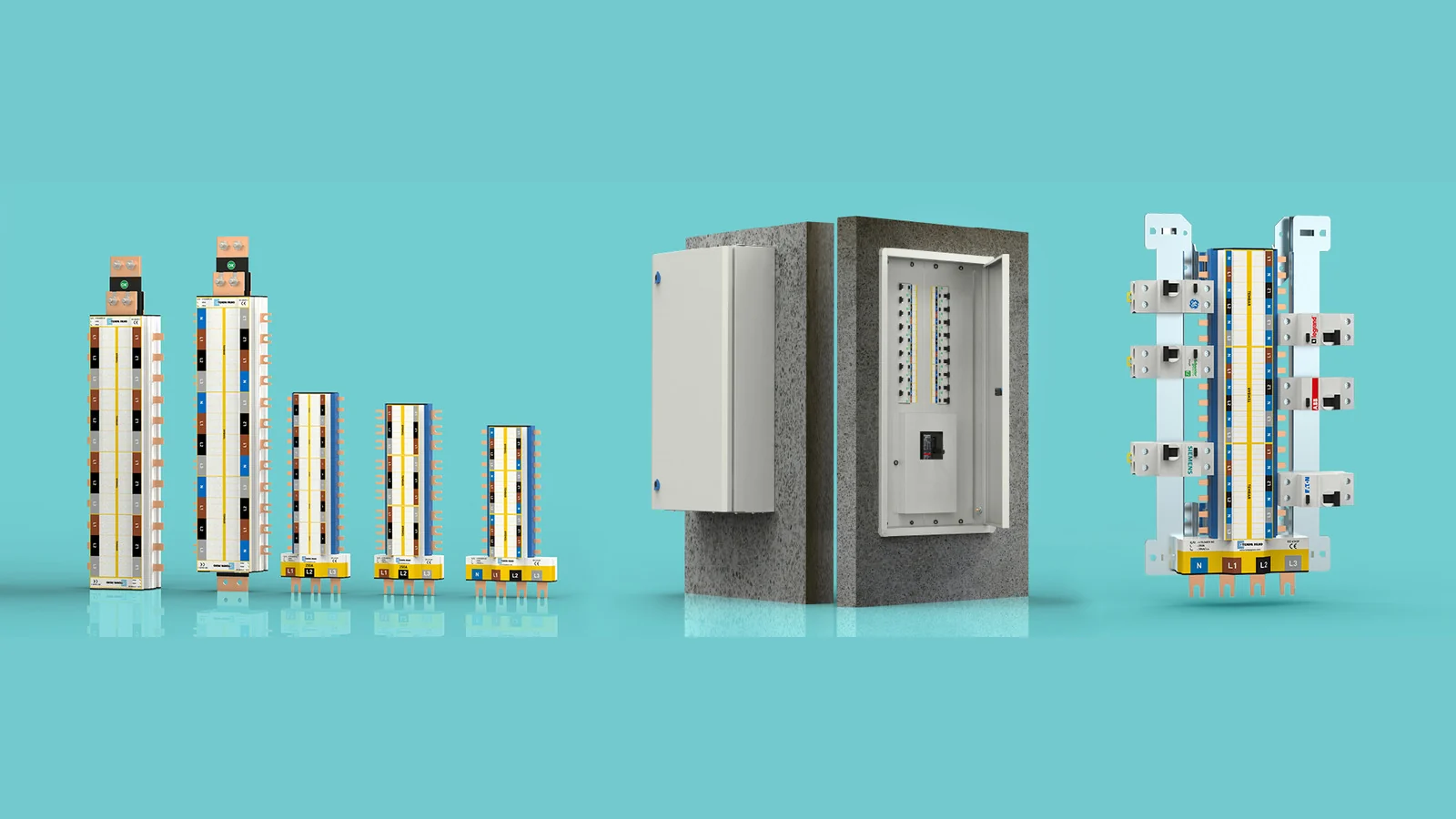
Tempa’s official product pages categorize its busbar solutions according to different application scales. K-BAR focuses on high-current requirements and robust mechanical structures in main distribution panels. The EASYBAR series offers modular connection options without the need for drilling, available in 630 A, 1250 A, and 1600 A ratings. The TM, TT-TM, and TT-TTS series create more compact, fully insulated distribution units. TDK panels, on the other hand, integrate the busbar system along with earthing and neutral connections into a ready-to-use distribution enclosure.
These groups are not simply larger or smaller versions of each other. The connection techniques, pole arrangements, protection methods, and the desired panel architectures all differ. When selecting the main busbar, factors such as current capacity, simultaneity of load, and expected growth rates are taken into consideration. For secondary distribution systems, the number of outlets, the size of protective devices, the direction of cable routing, and the ease of maintenance on-site are key considerations. In most projects, the most optimal configuration involves using different families of components in the right combination along the same circuit.
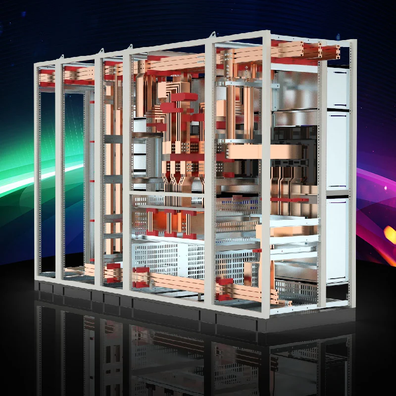
K-BAR: drill-free connections for high currents
On Tempa’s official website, the K-BAR is described as a busbar system designed for applications with currents up to 4000 A. It is available in three different cross-sectional configurations. The design allows connections to be made on the busbar without the need for drilling, which simplifies the arrangement of terminal points in the project, reduces installation time, and facilitates subsequent maintenance and modifications. The large cooling surface helps to regulate temperature, while the profile’s geometric design enhances its mechanical strength and the reliability of the connections.
The manufacturer states that the K-BARs have undergone temperature rise and short-circuit resistance tests in accordance with IEC 61439-2. However, this does not imply that every panel design automatically complies with these standards. Parameters such as bar length, support spacing, ventilation within the panel, connection points, ambient temperature, and protection arrangements are specific to each individual project. The expected peak currents during short circuits, as well as the required short-term resistance, must be verified in conjunction with the location of mechanical supports.
EASYBAR: modular distribution with three current options
The EASYBAR series is available in 630 A, 1250 A, and 1600 A ratings on the official website. The system utilizes specialized connecting components that eliminate the need for drilling, featuring a dual-bar channel design and insulated support structures. This approach facilitates repeatable installation in standardized panel modules. However, it is essential to strictly follow the manufacturer’s instructions regarding the torque of the connecting components, the contact surfaces, the connection geometry of the protective devices used, and all other installation details.
While a connection without fixed constraints provides flexibility, it does not imply unrestricted permission to make changes. When adding new outlets, factors such as the load, simultaneity, busbar capacity, and the risk of short circuits must be re-evaluated. The phase sequence, neutral conductor, and protective conductor must be clearly marked; covers and transparent protective devices must be in place to prevent accidental contact. If periodic inspections using thermal cameras are required, safe access to the measurement points must be considered during the project planning phase.
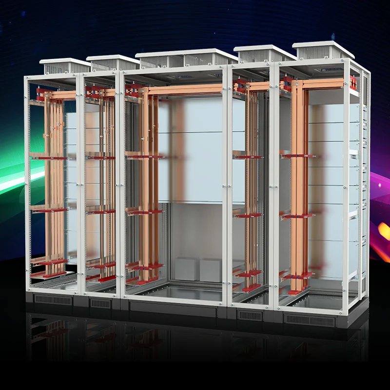
TM, TT-TM and TT-TTS: fully insulated compact distribution
The TM series is officially listed in product specifications with current ratings of 100 A and 250 A, and a voltage of 415 VAC. Its one-piece copper construction, color coding, and protective covers make it an ideal compact distribution component. The manufacturer specifies a conditional short-circuit current rating of 30 kA. The term “with specified conditions” is crucial; the stated performance should be interpreted in conjunction with the appropriate overcurrent protection devices and the test conditions defined by the manufacturer. It is not acceptable to assume that a component is suitable for short-circuit applications based solely on the current rating indicated on its label.
The TT-TM series is available for 400 A and 800 A applications at 415 VAC, while the TT-TTS series is designed for 250 A applications at 415 VAC. According to the variant, the TT-TM series can handle short-circuit currents of 50 kA or 70 kA for one second, whereas the TT-TTS series can withstand 30 kA of short-circuit current for the same duration. The number of poles, the layout of inputs and outputs, the connection dimensions, and the protective covers are all determined based on the specific project requirements. The fully insulated housing helps to ensure safety during maintenance; however, it is still essential to follow procedures such as de-energization, proper labeling, and the use of appropriate personal protective equipment.
TEMBAR and the product family's role in the system
TEMBAR represents the modular busbar approach utilized in Tempa’s distribution system diagrams as well as in ready-made panel solutions like TDK-S. Its color-coded phase and neutral wiring layout, along with accessories designed for the seamless integration of protective devices from various brands, enable a compact and organized installation. When selecting this product, factors such as the location of the main switch, the number of outputs, the type of single- or three-phase load distribution, and the neutral current capacity must be taken into consideration.
In modern facilities, non-linear loads can cause higher currents than expected to flow through the neutral conductor. Therefore, the assumption that “the phases are balanced” must be verified through measurements or load calculations. For loads with high harmonic content, such as those associated with data systems, lighting, or electronic power supplies, the neutral current and the resulting thermal effects also need to be considered. The use of TEMBAR or any other similar family of products does not eliminate the need for such engineering calculations; rather, it provides a hardware foundation that facilitates the proper operation of the system.
TDK distribution panels: combining busbars, enclosures and assembly
The TDK family provides pre-configured busbar distribution systems within the control panel enclosure. The TDK-S product page details the TEMBAR system, including features such as earthing and protective neutral bars, adjustable mounting configurations, cable transition plates, concealed hinges, the ability to change the panel orientation, and a RAL 7035 finish. As a result, this distribution system is not merely considered as a set of bare busbars but also takes into account ease of access and cable management.
When deciding whether to install the control panel flush-mounted or surface-mounted, factors such as the wall structure, cable entry points, service areas, and architectural requirements must be taken into consideration. The opening of the control panel doors must not restrict escape routes; the main switches and labels must be easily visible to operating personnel. Cable routing, bending radius requirements, and fire prevention measures must all be included in the field installation package. The size of the distribution panel’s enclosure is determined not only by the number of modules but also by connection requirements and thermal conditions.
Product family comparison table
| Family | Positioning on the official product page | Key selection consideration |
|---|---|---|
| K-BAR | High-current busbar systems with three cross-sections, capable of handling currents up to 4000 A. | Short-circuit calculation, support span, temperature rise, and main distribution layout. |
| EASYBAR | 630 / 1250 / 1600 A drill-free modular busbars | Connection components, torque, device geometry, and expansion plans. |
| TM | 100/250 A, 415 VAC fully insulated distribution system | Number of outputs, protection coordination, and the context of conditional short-circuit protection. |
| TT-TM | 400 / 800 A, 415 VAC fully insulated distribution system | Variants, pole arrangement, connection cross-section, and short-circuit levels. |
| TT-TTS | 250 A, 415 VAC compact distribution system | Enclosure space, output arrangement, and upstream protection |
| TDK | Ready-to-use busbar distribution systems, enclosed in protective enclosures. | Mounting type, cable entry, neutral/ground configuration, and accessibility. |
Project data required for correct sizing
The first type of data is the one-line diagram. It shows the power supply source, transformer capacity, cable impedance, protective devices, the nominal and operating currents of the loads, as well as the future output values. The simultaneity factor is determined based on actual operational data. Subsequently, the expected short-circuit current at the point where the panel will be connected is calculated. The thermal and dynamic strength of the busbars and conductors, along with the tripping time of the protective devices, are also taken into consideration during this process.
Factors such as ambient temperature, internal ventilation within the panel, side-by-side arrangement, and elevation can all affect the degree of temperature increase. The contact resistance of the connections, the application of the correct torque, and the proper preparation of the conductor surfaces are also essential for optimal performance. Phase loads must be balanced, and the neutral conductor, protective conductors, and equipotential connections must be properly installed according to the design specifications. Upon completion of the installation, visual inspections, tests for tightness, continuity, insulation quality, and functional performance must be conducted and documented.
Maintenance, measurement and safe intervention
In bar-connected distribution systems, faults often begin when a loose or dirty connection heats up. The manufacturer’s specified torque values must be applied during production and recorded in the quality documentation. Depending on the operating conditions, thermal imaging, visual inspection, or scheduled maintenance checks can be conducted to verify the connections. Failing to install the covers properly or misassembling them after maintenance can weaken the electrical protection measures in place.
When adding a new outlet, it is not sufficient to simply ensure that there is sufficient physical space available. The total load, the level of short-circuit protection, the selection of protective devices, phase balance, and the temperature of the busbars must all be rechecked. The necessary changes are then recorded in the single-line diagram and on the panel labels. This process ensures that the flexibility offered by the modular system is used in a safe and reliable manner.
From design to commissioning with Oskon
Oskon examines the existing distribution system and growth objectives during site exploration; it transforms load lists, short-circuit analysis results, and selection criteria into technical design specifications. The Tempa busbar family and control panel enclosure are selected based on the application’s current-carrying capacity and access requirements. The layout of the busbars, protective devices, measurement systems, cable connections, as well as the neutral and grounding systems are all designed together. Following manufacturing and FAT, on-site connections are completed, functional tests are conducted, and a thermal monitoring plan is established.
During the bidding phase, it is necessary to provide the current single-line diagram, information regarding transformers and power supply systems, a list of loads, the expected level of short-circuit current, the cross-sectional dimensions of input and output cables, the location of the control panel, the ambient temperature, and any expected future expansion requirements. If these data are not available, Oskon should be informed accordingly. Automation consulting service can provide measurement and design support. This connects product selection to the facility’s actual power distribution requirements.
Official product sources: This guide is based on Tempa Pano’s Busbar and Distribution Systems, K-BAR, EASYBAR, TM, TT-TM, TT-TTS and TDK pages. Confirm final values against current technical documentation and project calculations.