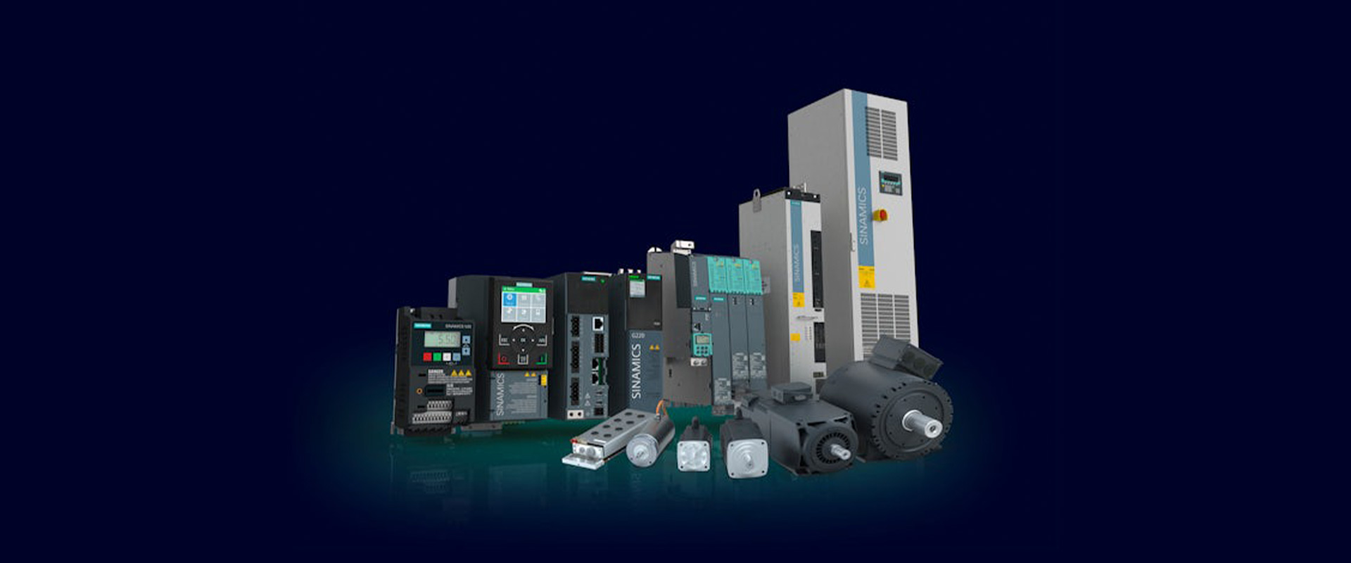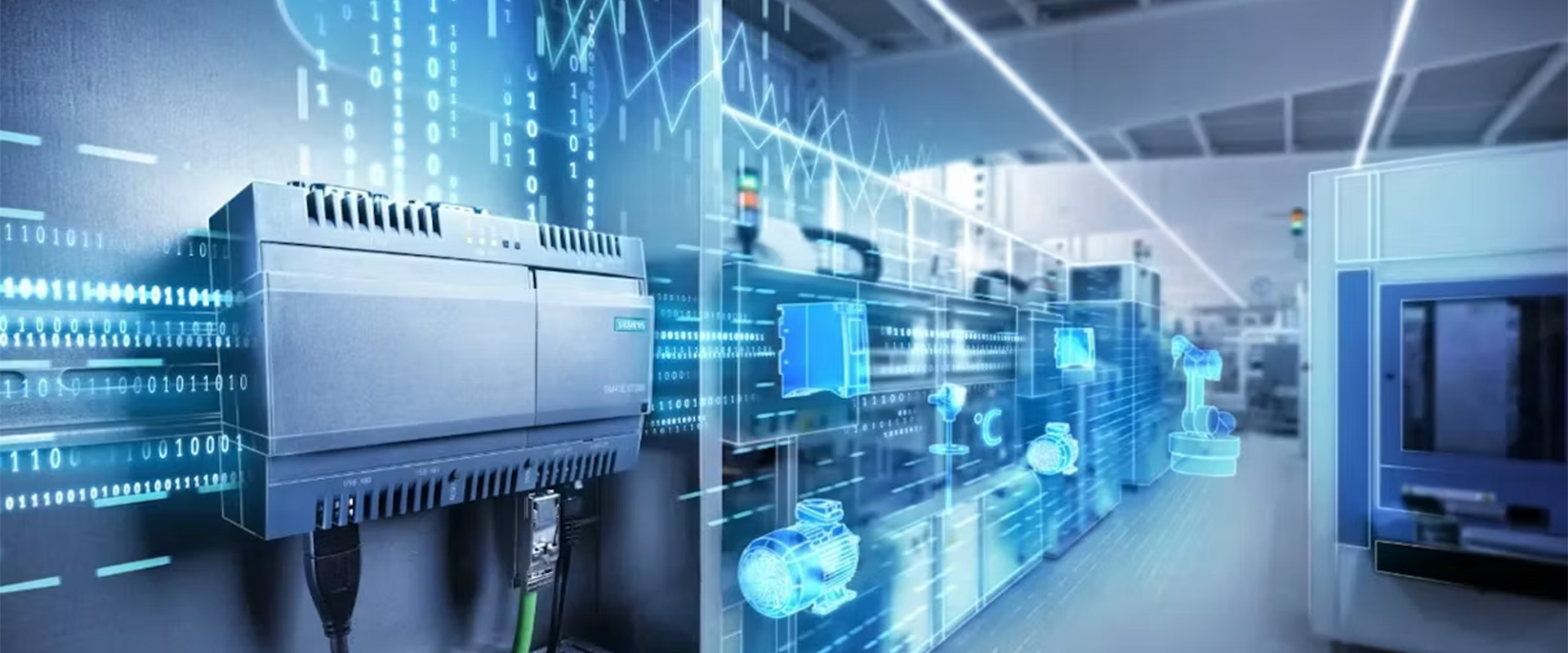
The Advanced Factory Automation approach considers controllers, distributed I/O components, motion systems, operator interfaces, and industrial communication systems not as separate individual components to be purchased separately, but rather as different layers that work together toward the same production goal. The SIMATIC automation family and SIMATIC NET communication components help to establish continuity in control, data transfer, and diagnostic functions within this framework. The right solution is not merely about choosing a single PLC or Ethernet switch; rather, requirements such as cycle time, topology, availability, security, maintenance considerations, and the entire product lifecycle must all be defined within the same architectural framework from the very beginning of the planning phase.
What does Advanced Factory Automation mean?
Advanced factory automation aims to make production behaviour measurable before adding more devices. Meeting the required control cycle, commissioning line sections independently, locating faults accurately and managing product changes in a controlled way are equally important. Assess the architecture as a whole: centralised or distributed control, network segments, I/O placement, drive synchronisation, HMI alarms and data flows to higher-level systems.
Siemens' current SIMATIC page positions S7 controllers, ET 200 peripherals and TIA Portal engineering tools as core elements of integrated automation. SIMATIC NET is the umbrella for the industrial communication side of this architecture. PROFINET, industrial Ethernet, SCALANCE network components, wired and wireless access, and diagnostic tools fulfil different tasks. Saying 'we use SIMATIC NET' is therefore not, by itself, a specification for ports, protocols, performance or security.
The control layer: selecting SIMATIC S7-1500 performance for the task
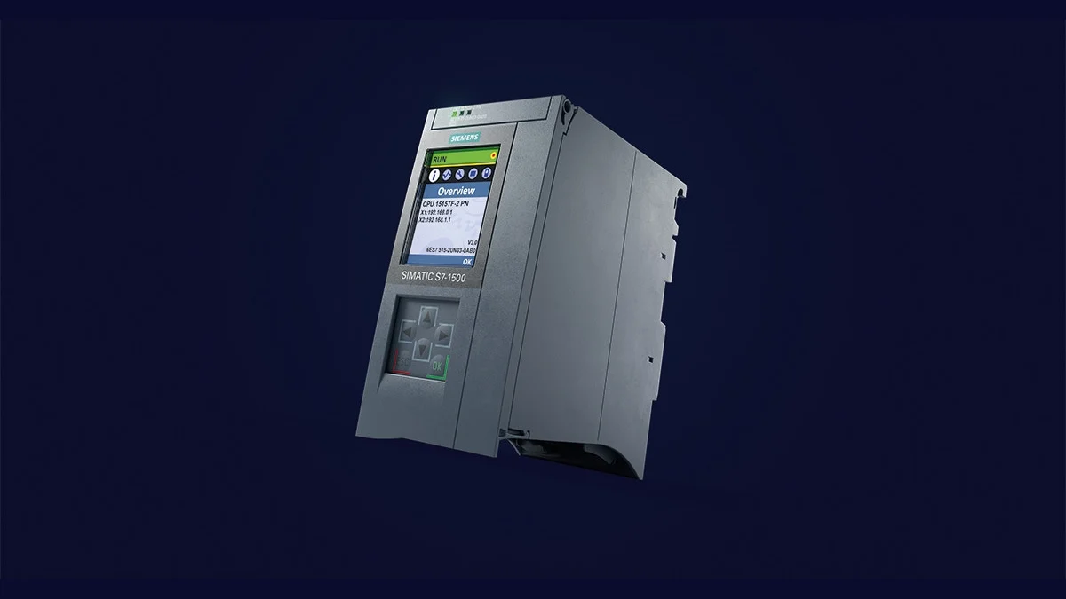
SIMATIC S7-1500 is Siemens' high-performance hardware PLC family for complex machine and plant tasks. The current product page highlights integrated configuration, programming, diagnostics and maintenance in TIA Portal, together with communication options over PROFINET, industrial Ethernet and OPC UA. The family name does not mean every CPU offers the same memory, interfaces or technology functions. Calculate program size, data requirements, cycle load, communication connections and future expansion margin for the exact CPU variant.
Consider general-purpose CPUs for standard control, technology CPUs (T-CPUs) for demanding axis and kinematic applications, and F or TF variants when a safety program is required on the same hardware. Integrating motion control through software objects can simplify engineering, but mechanical cycles, encoder resolution, drive telegrams and PROFINET IRT requirements still need verification. Selecting a CPU with safety functions does not automatically make a machine safe. Risk assessment, safety function architecture, response time and validation documentation remain project responsibilities.
Why is I/O count alone insufficient for controller sizing?
Two machines with the same digital I/O count can impose very different processing loads. One line may need recipe management, traceability, serial communication and hundreds of alarms, while another runs a few simple sequences. Include fast interrupts, technology objects, safety programs, communication data blocks, web or OPC UA access and HMI clients in CPU load calculations. Test initial power-up, when all devices reconnect, and bursts of diagnostic messages as well as normal production cycles.
Operating continually near the resource limit makes future software changes harder. Leave memory and processing-time headroom in the design, and record cycle time distribution and peak load during acceptance. These records provide a baseline for measuring later revisions. Changes can then be assessed for their effect on deterministic behaviour, rather than merely whether the program still runs.
The distributed field layer: SIMATIC ET 200SP
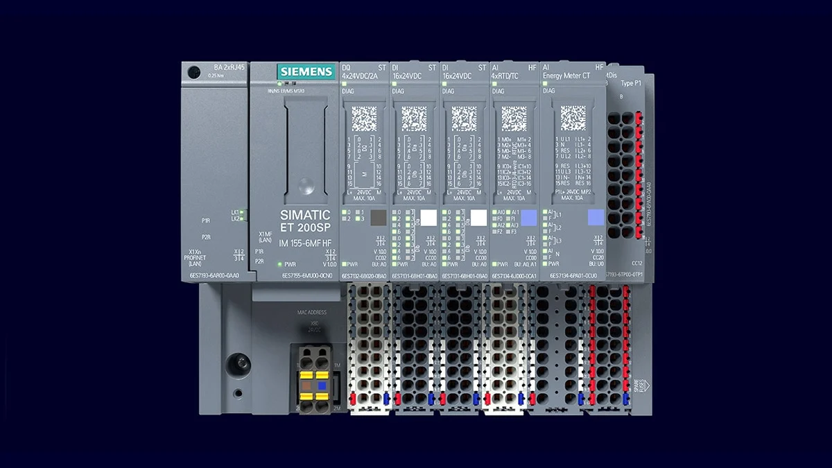
SIMATIC ET 200SP is a compact, modular distributed I/O system for installation inside control panels. Siemens' current page highlights its suitability for small control boxes, broad module ecosystem, diagnostics, expandability and, with the appropriate components, replacement of multiple modules during operation. Combining digital and analogue I/O, technology, communication, safety and motor-starting tasks within one station concept helps organise panel space and field wiring.
Correct station design begins by defining field boundaries before listing modules. Which machine section will remote I/O serve, how will its power be isolated, which panel will maintenance staff access, and what will the safe output state be after network loss? Sizing solely by channel count before answering these questions may shorten cables while allowing a fault to stop a much wider production area. Power groups, potential separation, spare channels and terminal labelling also belong in the station plan.
ET 200SP station decisions beyond the quotation line item
- Interface and protocol: Match the required PROFINET functions, network redundancy, performance class and system capacity to the exact interface module.
- BaseUnit and Potential Group: The terminal type, new group start, AUX distribution, and color code should be selected in accordance with the electrical schematic diagram.
- Module capabilities: Check input electrical characteristics, output current, analog resolution, diagnostics and safety rating as well as channel count.
- Thermal layout: The requirements for horizontal or vertical mounting, ambient temperature, spacing, and load reduction values can be found in the current user manual.
- Maintenance strategy: Test hot swapping, automatic parameter loading and spare-part replacement against the functions supported by the selected station.
SIMATIC NET and PROFINET: design the communication service, not just the cable
PROFINET establishes Ethernet-based automation communication between controllers, distributed I/O devices, drives, and other field devices. Within the same physical environment, cyclic process data, standard TCP/IP communication, and diagnostic messages can coexist. However, this compatibility does not imply that “any Ethernet network is sufficient for PROFINET applications.” The specific requirements—such as device role, real-time performance, update interval, network depth, cable and connector specifications, electromagnetic environment, and network load—must be determined based on the specific project requirements.
PROFINET RT may be sufficient for standard motion or I/O tasks, while high-precision synchronised motion may require IRT. Keep this decision consistent across controllers, drives, switches and topology. MRP ring redundancy can improve availability after a cable break, provided all devices have suitable roles and settings in the same ring domain. A 'redundant network' is not an acceptance criterion until reconfiguration time has been compared with the downtime production can tolerate.
Managed machine networks with SCALANCE X-200
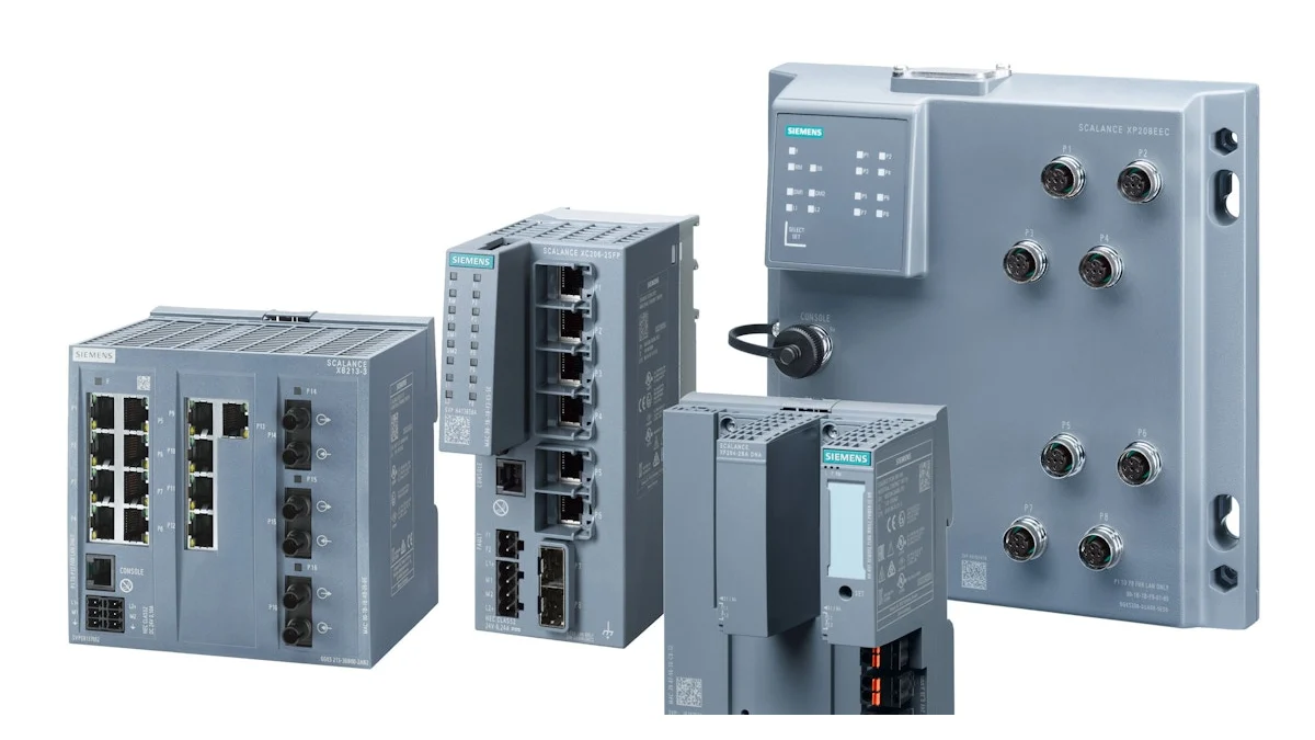
The SCALANCE X family offers options for switching, routing, security, and wireless communication in industrial Ethernet networks. The X-200 product line provides manageable network functions, industrial-grade design, and diagnostic tools for applications ranging from the machine level to interconnected plant components. The devices within this family vary in terms of the number of ports, connection type (copper or fiber), Gigabit support, PoE functionality, protection class, and PROFINET compatibility. Therefore, it should not be assumed that two switches with similar appearances will perform the same functions in the same network topology.
A managed switch offers more than VLAN configuration. Port status, neighbour information, error counters, port mirroring, ring management and central network monitoring can shorten troubleshooting. Define device names, port descriptions, the IP plan, VLAN matrix and alarm destinations in the project standard. Factory acceptance should include removing a cable to observe ring behaviour, incorrect port connections, broadcast traffic and power-loss scenarios.
Which component addresses each architectural requirement?
| Project requirement | Priority layer | Item to verify in the quotation |
|---|---|---|
| Complex sequences and intensive data processing | SIMATIC S7-1500 controller | Processing load, memory, interface, OPC UA functionality, and growth potential. |
| Synchronous axes or kinematics | S7-1500 technology CPU and PROFINET | Technology objects, drive telegram, IRT and mechanical cycle |
| High field-signal density near the cabinet | SIMATIC ET 200SP | Interface module, channel type, power supply group, temperature setting, and spare channel. |
| Diagnosable cell or line network | SCALANCE Managed Switch | Port media, speed, VLAN, MRP role, monitoring and environmental conditions |
| During the initial commissioning process, topology testing and I/O testing are carried out. | PRONETA and TIA Portal tools | Supported devices, reference topology, test records, and versions. |
| Controlled data exchange between the OT system and the higher-level system. | Network segmentation and appropriate interfaces | Data owner, protocol, certificate, firewall, and access rights. |
Shared engineering in TIA Portal does not automatically create a shared standard
SIMATIC STEP 7 is used within TIA Portal to configure, program, test and diagnose controllers. A common environment for the hardware catalogue, network view, PLC software and online diagnostics supports project consistency. However, a shared tool alone does not standardise projects if engineers use different naming, alarm and block structures. Establish a company library, version policy, code review criteria and device naming template separately.
Reusable blocks, technology object templates and HMI faceplates speed up machine-series engineering. Make each library element's version, dependencies and test results visible. If temporary online changes are not incorporated into the project archive, the running field version and source files diverge. Handover must include a compilable project, hardware configuration, device software list, a password and certificate handover method, and a completed restore test.
Commissioning: PRONETA, system diagnostics and acceptance records
Siemens’ PRONETA tool can scan a PROFINET network to visualize its topology, assist in assigning device address parameters, and enable testing in supported distributed I/O systems without the need for a PLC. The capabilities of the Basic and Professional versions differ; required features must be verified via the license and the current compatibility list. This tool does not replace a properly designed network but helps in promptly identifying any discrepancies between the intended topology and the actual installation.
- Passive control: Before energization, the cable class, shielding, equipotential bonding, port labeling, and fiber orientation are all inspected.
- Naming: The PROFINET device name, IP address, station label, and electrical configuration are all matched through the same record.
- Topology scanning: True neighbor relationships and port connections are compared with the reference topology; any unused ports are identified.
- I/O tests: Verify every channel with a physical sensor or actuator; test open-circuit and short-circuit diagnostics as well as normal values.
- Load and fault testing: Record network load, update time and error counters during the busiest production cycle; test a break in the ring.
- Restore from backup: Verify configuration restoration time and the responsible person for controller, station or switch replacement.
Consider industrial cybersecurity and availability together
A production network operating successfully does not mean it is secure. VLANs, managed switches and firewalls are technical tools; risk assessment determines which assets they protect against which threats. Segment control cells by function, restrict connections to the business network through allowlists and enable remote service only for the required time. Default credentials, shared administrator accounts and unregistered laptop access can undermine even a well-designed topology.
Siemens emphasises that its products are only part of a comprehensive, continuously updated industrial security approach. Monitor firmware and security advisories regularly; test updates in a controlled environment, prepare a rollback plan and record production changes. Keep backups offline or under access control, and associate configuration changes with authorised users. Network redundancy, backups and cyber resilience complement one another but are not substitutes.
Information checklist before quotation and implementation
- Machine sections, target cycle time, simultaneous movements, and stoppage costs.
- Standard and safe I/O quantities, types of analog signals, technology modules, and spare capacity.
- Controller functions, program and data capabilities, OPC UA, or other connections to higher-level systems.
- Number of PROFINET devices, requirements for RT/IRT, update frequencies, line depth, and topology.
- Copper/fiber medium, cable routing, EMC requirements, panel temperature, and protection class.
- MRP, system redundancy or other availability targets, and allowable recovery time
- VLAN and IP planning, firewall rules, user roles, and remote service procedures.
- TIA Portal, device software, and hardware versions; library, backup, and acceptance testing standards.