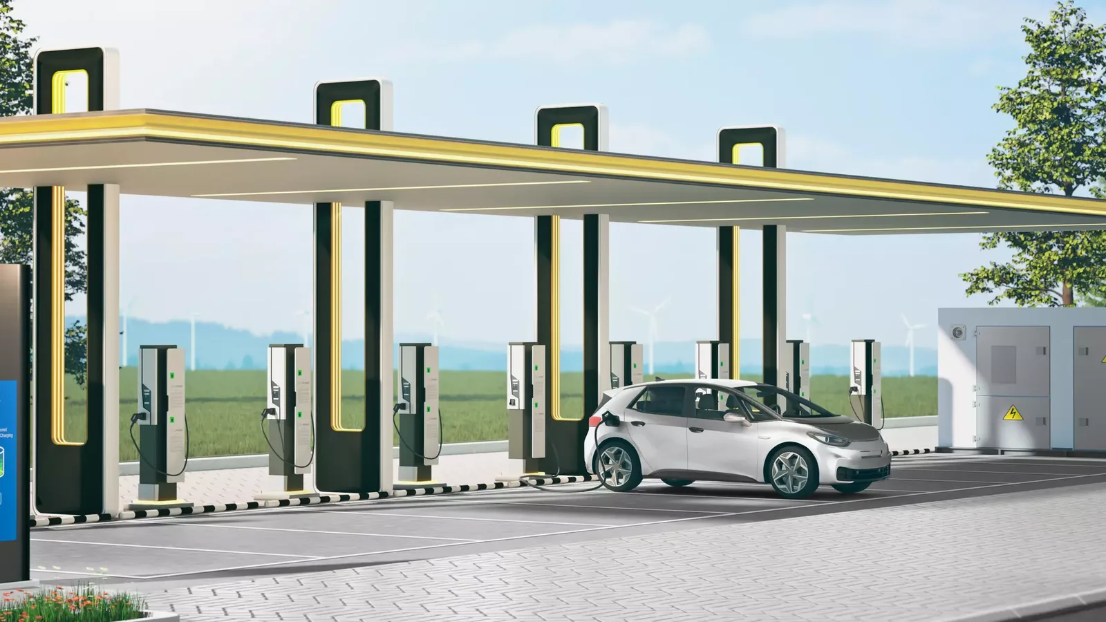
The selection of charging equipment for electric vehicles cannot be based solely on the maximum wattage capacity of the cable. The vehicle’s connection standards, charging mode, type of current (AC or DC), number of phases, nominal current and voltage, cable length, environmental conditions, mechanical design requirements, and the architecture of the charging station are all essential factors that must be taken into consideration. HARTING’s current product range includes Mode 3 Type 2 AC charging cables, Mode 4 CCS Type 2 DC cable assemblies with vehicle connectors, as well as charging sockets and connector holders. HARTING’s broader portfolio of solutions for the electric mobility sector also encompasses technologies for in-vehicle power and data connections, as well as infrastructure components for charging systems.
This guide is designed to help you select HARTING charging products for fleet, workplace, commercial, or equipment manufacturer projects by ensuring that the correct requirements are met. A single cable or socket alone does not constitute a complete charging station; additional components such as energy protection systems, switching devices, measurement instruments, communication systems, user authentication mechanisms, mechanical enclosures, thermal management systems, and infrastructure connections must also be carefully designed. The values for power output (22 kW, 350 kW), current, voltage, IP protection levels, and charging cycles mentioned in this document specifically refer to the products identified by their names and order numbers. These specifications cannot be automatically applied to products with different lengths, conductor cross-sections, standards, or regional variations.
Distinguish charging mode, connector standard and current type
Mode 3 refers to the controlled connection of an electric vehicle to an AC charging station, while Mode 4 denotes the provision of direct current by a DC charging device to the vehicle’s battery. The terms “Type 2” and “CCS Type 2” relate to the geometry of the plug and the arrangement of its contacts; these terms are not interchangeable. A Mode 3 Type 2 cable includes AC power contacts as well as CP and PP signal contacts, whereas a CCS connection combines these with additional DC power contacts to form a unified interface. Projects should not be designed based on the assumption that the vehicle’s connectors and the charging station’s outlets conform to the same regional standards.
Charging power is primarily related to voltage and current; the actual amount of energy transferred is determined by additional factors such as the vehicle’s charging electronics, battery management systems, station capacity, infrastructure connections, and temperature conditions. The label “22 kW” on a cable does not mean that every vehicle can be charged at this rate. Similarly, the maximum value specified in the catalog for a DC cable does not represent the continuous power available throughout the entire charging cycle. The selection of a product should take into account the expected usage pattern, the number of vehicles that will be charged simultaneously, and the control strategies employed by the charging station.
Selecting Mode 3 Type 2 AC cables
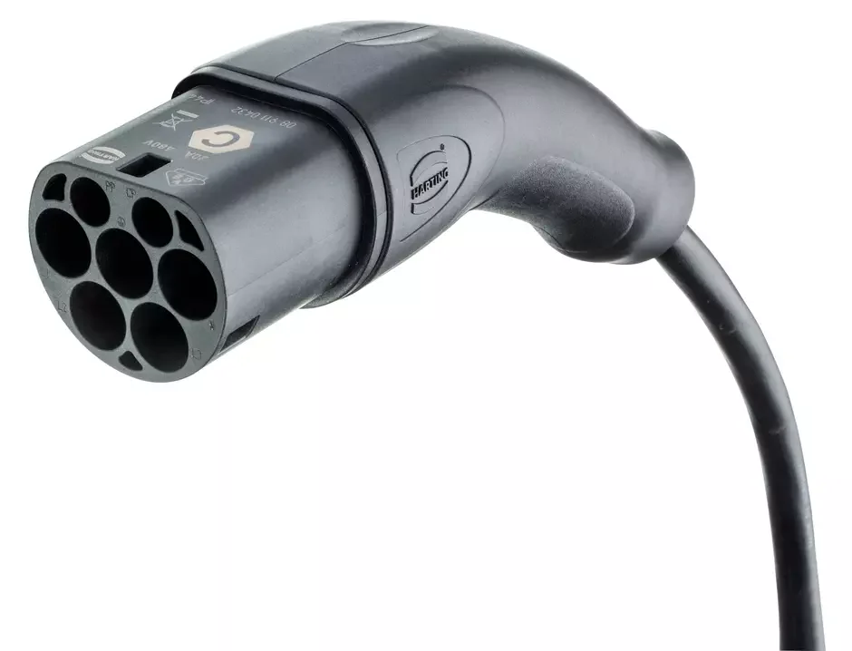
HARTING’s product range includes Mode 3 Type 2 connectors in both single-phase and three-phase versions, with various current ratings and cable lengths. It is important to check the product description to determine whether the cable comes with female Type 2 connectors on the vehicle side for portable use, or male Type 2 connectors on the infrastructure side; alternatively, it may be available with open ends for fixed installation in a wallbox. Two cables that appear identical may actually differ in the number of phases or their internal conductor configuration. The PP coding and the CP signal path are essential system components that ensure the cable can handle the specified current rating and enable proper charging control; mechanical compatibility alone is not sufficient.
A specific product example is Charg.c.Mode3 22KW Type2 G2 32A 3ph 2.5m, 08 91 409 0115 B0 is listed on HARTING’s website as Type 2 connector with flat cable, featuring a female connector on the vehicle side and a male connector on the infrastructure side. The cable length is 2.5 meters, and it supports three-phase power transmission with crimped terminations. For this specific model, the power contacts are specified to handle 32 A at 480 V, providing 22 kW of power; the signal contacts are rated at 2 A and 30 V. The operating temperature range is from −30 to +50 °C. The connector is designed with IP44 protection rating, and its mechanical life is guaranteed to be at least 10,000 mating cycles. Additionally, the minimum bending radius required for repeated bending is nine times the cable diameter.
Read these values together with the product code as design inputs. IP44 applies to the mated connection; the same protection cannot be assumed for an exposed plug, dirty contacts, or a damaged gasket. At least 10,000 mating cycles is not an unlimited-life promise covering dropped cables, vehicles driving over them, or bending below the specified radius. Cable routing must match the actual distance between station and parking space, avoiding both excess loops on the ground and tensile loads from insufficient length.
Mode 4 CCS DC fast-charging cables
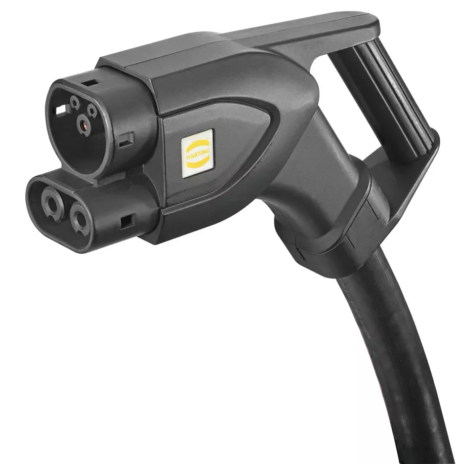
In DC fast charging, the power conversion is performed by the charging station, and energy is transmitted to the vehicle via DC contacts. High current levels require careful consideration of contact resistance, conductor cross-section, cable weight, and temperature monitoring requirements. Therefore, the selection of CCS cables cannot be based solely on the plug type. It is essential to take into account factors such as the station’s maximum DC voltage, current-time profile, cable cooling methods, ambient temperature, vehicle-side limitations, and the response of the control system’s temperature sensors. The power rating specified on the manufacturer’s page does not necessarily imply that all these factors are automatically taken into account in the actual system design.
Vehicle Plug CCS Gen2 Typ2 4x50² 3,0m, 08 96 308 1801 A0 is an example of a Mode 4 cable that indicates its technical specifications based on its product code. HARTING specifies that this three-meter-long CCS Gen2 Type 2 vehicle-side plug cable can handle a current of 350 A at 1000 V DC and at a temperature of 25 °C, resulting in a power output of 350 kW. The product data includes information on temperature monitoring using two Pt1000 sensors, a shutdown temperature of 90 °C, as well as the power contact configuration of DC+, DC−, and PE. The specifications also state that the cable is capable of 30,000 mating cycles, has an IP44 rating in the mated state, an IP69 rating in the body area, and a minimum bending radius nine times the cable diameter.
These specifications are applicable solely to the model 08 96 308 1801 A0. It is particularly important that the current be supplied under the condition of 25 °C. Higher ambient temperatures, damaged insulation of the cable, contamination of the contact surfaces, or variations in the length of the product can all affect its thermal performance. The presence of a sensor alone does not guarantee safe shutdown; the measurement circuit, detection of cable disconnections/short circuits, threshold settings, station control logic, and the safe power-off mechanism must all be verified together. Additionally, the product’s compliance with the relevant standards IEC 62196-1, IEC 62196-3, EN 50620, and EN 60751 must be confirmed through the selected code and accompanying documentation.
Cable length, thermal behaviour and ergonomics
The length of the cable is determined based on the various parking positions of the vehicles and the location of the charging ports. The cable must reach the farthest target without being stretched excessively, but at the same time, it should not have enough excess length that could cause it to get tangled on the ground or pose a risk of coming into contact with vehicle wheels. DC high-current cables may be thicker and heavier; in such cases, user-accessory devices, hanging systems, retraction mechanisms, or specialized carrying systems may be required. Cable management systems are necessary to protect the connector from excessive pulling forces and ensure that the allowable bending radius is not exceeded. Excessive tight twisting, knots, or repeated bending at the same point can cause premature wear on both the outer sheath and the conductor.
Thermal calculation is not merely limited to the nominal current table. Factors such as the number of daily charges, the duration of each charge, the cooling time between charges, direct sunlight exposure, the type of cable reel used, ambient temperature, and contact resistance measurement plans must also be taken into account. During the initial commissioning and periodic inspections, it is essential to compare the temperatures of the plug, the contact areas, the cable, and the terminals. Abnormal temperature increases can indicate the presence of dirt, wear, looseness, or damage. No chemicals or oils should be applied to the contact surfaces unless otherwise specified by the manufacturer; the cleaning and inspection procedures must comply with official maintenance guidelines.
Treat charging sockets and plug holders as system components
Within HARTING’s product range, Type 2 charging sockets and plug holders are also available. The current catalog lists Type 2 sockets with three-phase functionality and a power capacity of 22 kW, which may be equipped with motorized or magnetic locking mechanisms. However, this information does not imply that all these sockets share the same mechanical design. Details such as the socket’s panel layout, front/rear mounting options, cable termination requirements, locking voltage levels, locking position feedback systems, emergency release functions, and environmental protection features must be confirmed based on the specific product code.
A plug holder does not transfer energy; rather, it serves as a mechanism that keeps the end of the cable away from water, dirt, and impacts on the ground. The position of the holder must be at a height that allows the user to access the cable easily without exerting force, and it must also prevent the plug from falling. In the case of a socket-based station, the socket cover, locking mechanism, and drainage system are crucial if the cable belongs to the user; for a station with a fixed cable, the cable hanger and the connector socket play a key role in ensuring the device’s durability. For both types of setups, factors such as accessibility for people with disabilities, parking requirements, nighttime lighting, and the risk of mechanical damage must be taken into consideration during the facility’s design phase.
The cable is only the charging station's external interface
The electrical design of a charging station includes aspects such as the power supply capacity, short-circuit protection levels, cable cross-sections, overcurrent and leakage current protection mechanisms, the layout of fuses, contactors, meters, and protective conductors. The specific protective devices required must be determined by a qualified designer in accordance with national regulations, the type of facility, the design specifications of the charging equipment, and the manufacturer’s instructions. The catalog values of HARTING cables cannot replace these protective and control functions within a charging station.
In smart charging applications, additional features such as user authentication, billing, load management, station networking, and communication with higher-level platforms are incorporated. The power demand of the facilities, as well as factors related to simultaneity and the departure times of vehicles, affect the control strategies implemented. In the event of a communication disruption, the station’s safe operating procedures, local charging authorization mechanisms, and event logging systems must be pre-defined. Even if the physical cables are compatible, the software protocols, vehicle-charging device communication, and payment infrastructure require separate integration efforts.
| Application | HARTING product area | Key information to verify in the quotation |
|---|---|---|
| Transferable connection from the AC station to the vehicle | Mode 3 Type 2 two-ended cable | Single/three-phase, current, power, connector genders at both ends, length, IP rating, and mating cycles |
| Integration of fixed cables within the wallbox | Mode 3 Type 2 vehicle plug cable with an open station end | Conductive structure, terminal preparation, terminals, temperature, tensile load, and seals |
| DC fast charging | Mode 4 CCS Gen2 Type 2 vehicle plug cable | DC voltage, current-temperature conditions, power, sensors, cross-section, length, and control. |
| AC charging using a user-supplied cable | Type 2 charging socket | Phase/power, lock type, panel mounting, feedback, and emergency release |
| Protecting the fixed cable in the parked position | Type 2 plug holder | Mounting height, mechanical fixation, water/dirt drainage, and accessibility. |
| Specialized station or vehicle-mounted component | Custom HARTING connection solutions for customers. | Development, validation, standardization, testing systems, and change management. |
Commissioning, inspection and maintenance
During the initial commissioning process, the continuity of the protective conductors, the insulation, the correct phase/voltage, the behavior of the control pilot signals, the locking mechanism, the sequence of power-on/off, and various fault scenarios must be tested in accordance with relevant regulations. The product code listed on the cable label, the station configuration details, and the current limits specified in the software must all be traceable within the same documentation. A successful connection in a single test device does not constitute proof of compatibility with all devices; instead, a field acceptance plan must be established in consideration of the target device range and various battery conditions.
During periodic inspections, it is necessary to check for cracks, burn marks, deformations, loose components, foreign substances, and moisture in the plug and socket. The outer insulation of the cable is examined for compression, breaks, wear, or abnormal hardening. The locking mechanism, as well as any temperature monitoring circuit, must be tested to ensure proper functionality. Damaged high-power cables must not be put into service using temporary patches or repairs whose suitability in the field has not been verified. When replacing a cable, the new product should be selected based on its order code, electrical specifications, sensors, length, and the scope of approval, rather than simply matching its appearance with the damaged one.
Data required for a quotation
- Describe the usage scenario: Indicate whether it is for charging private vehicles, fleets, workplaces, public charging stations, or machinery, as well as the daily usage and the need for simultaneous charging.
- Verify the vehicle interface: Type 2, CCS Type 2, or another regional standard; please indicate it together with the list of target vehicles.
- Select the charging mode: Determine whether Mode 3 AC or Mode 4 DC is required based on the vehicle and station design.
- Specify the electrical limits: Share the phase, nominal and maximum voltage, current, target power, duration, and temperature profile.
- Draw the cable layout: Indicate the fixed or detachable structure, the two types of ends, the length, the hanger/retractable system, and the parking geometry.
- Classify the environment: Record the risks of indoor/outdoor environments, as well as those related to temperature, sunlight, rain, ice, dust, chemicals, impact, and vandalism.
- Specify control and locking: Define the terms CP/PP, socket lock, sensor, emergency opening, power cut-off, and fault diagnosis system.
- Complete the protection project: Verify the design of the facility supply, short-circuit, overcurrent, residual-current and surge protection, and earthing with the responsible qualified party.
- Define the acceptance criteria: Identify electrical test requirements, test procedures for different types of vehicles, thermal monitoring requirements, communication protocols, as well as user ergonomics considerations and maintenance documentation.
Oskon and HARTING view charging products for electric vehicles not as individual components located outside the station, but rather as part of the energy and control chain that extends from the facility’s power supply to the vehicle entrance. The right product is one that mechanically matches the target vehicle, conforms to the actual current and temperature profiles, can be safely managed, and can be inspected by maintenance personnel. The availability and delivery time of the product must also be confirmed at the time of the offer; this information does not constitute any guarantee regarding stock levels, charging times, or compliance with local regulations at a specific location.