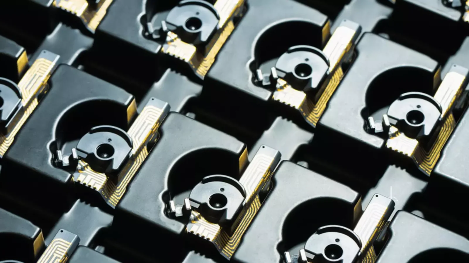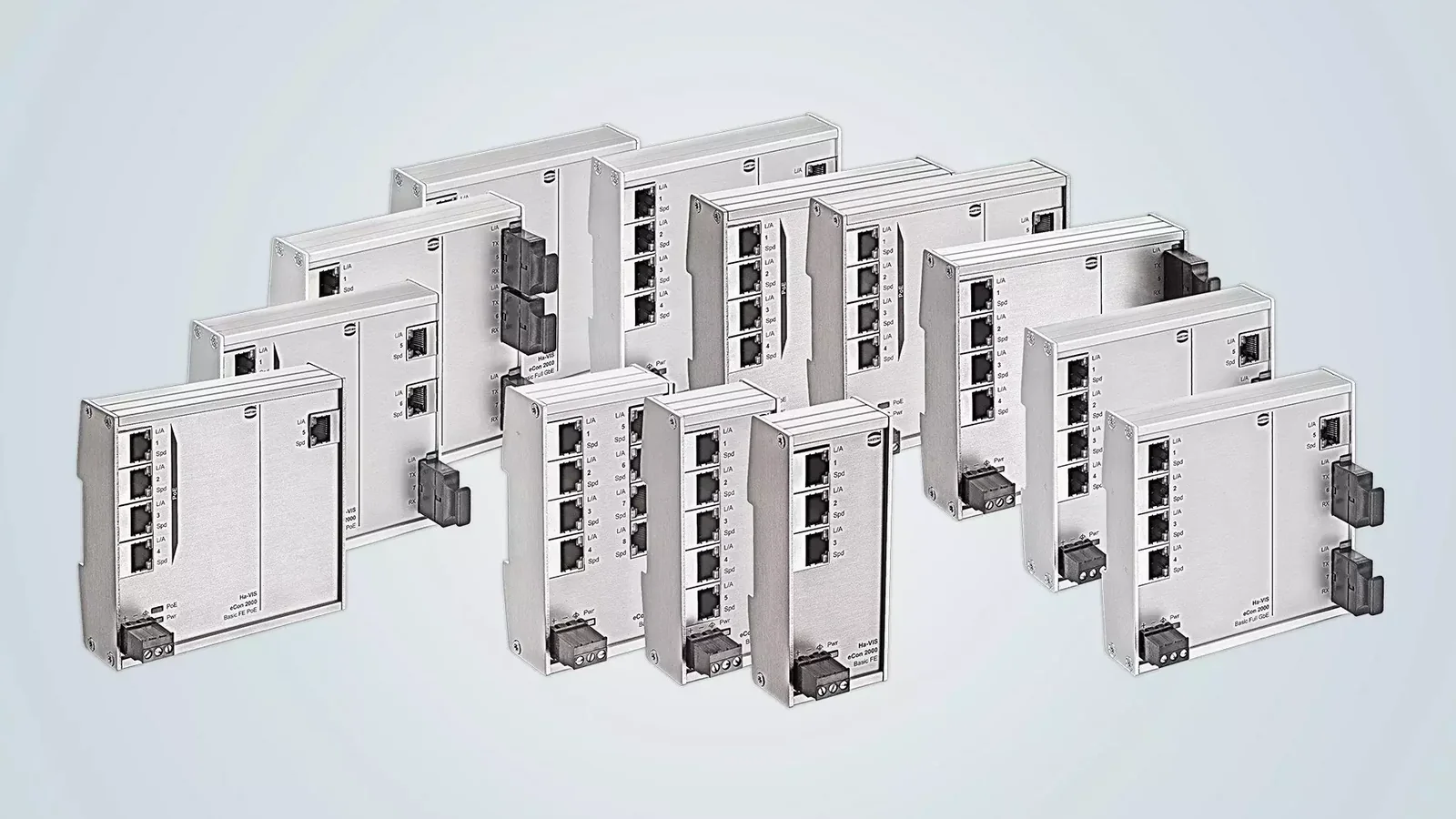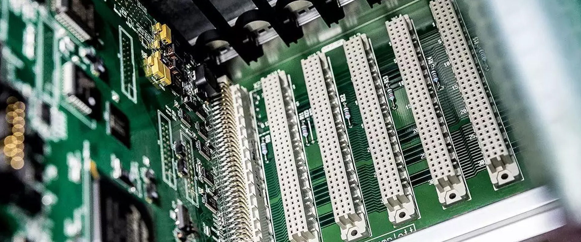
The interface between the external connections of a device and a printed circuit board cannot be designed solely based on the number of pins of the connector. The relative positioning of the boards, data transfer speed, continuous current capacity, cable configuration, shielding measures, contact reliability, the soldering process, and accessibility within the device’s enclosure all influence the final design choices. HARTING’s PCB connector portfolio encompasses various connection solutions, including PCB terminals suitable for inter-board connections, board-to-cable connections, and field wiring applications. Product families such as har-flex, har-flexicon, har-modular, and HARTING ix Industrial are designed to meet these different requirements in a range of application scenarios, considering factors such as connection density, manufacturing processes, and maintenance considerations.
This catalog guide explains the technical questions that must be addressed before converting product family names into a detailed quotation. First, the interface architecture and electrical specifications must be defined; subsequently, the number of contacts, card geometry, termination type, mounting method, cable outlet, mechanical fixation, packaging, and manufacturing process must be specified. The values for current, number of contacts, and other technical parameters mentioned in this text apply only to the specific example cited by its name and product number. These specifications cannot be generalized to different pole configurations, orientation options, or termination types within the same product family. The final choice of product is determined based on the HARTING technical data sheet, PCB layout information, soldering profile, and the device’s validation test results.
Divide the interface architecture into three main groups first
Board-to-board connections mean that two printed circuit boards are directly connected via a connector. Different connector geometries are required depending on whether it is a motherboard/daughterboard configuration, a parallel stacked arrangement, an extension card, or a right-angle card layout. The actual distance between the boards, the tolerance chain, the mating direction, and the mechanical support design are all critical factors. What needs to be controlled is not only the height of the connector itself, but also the total stacking height of the mated connectors and the keep-out areas on the circuit boards.
Board-to-cable connections link a device PCB to an enclosure, sensor, network, or another module. Options include detachable cable plugs, shielded data interfaces at the device edge, and crimp contacts in a cable harness. Strain relief, coding to prevent incorrect mating, operator access, and shield continuity to the chassis are important. Cable exits must clear the device cover, fan airflow, and other components.
PCB terminal block connections mean that the field conductor is directly connected to the terminals on the circuit board or to a plug that can be installed. Connection mechanisms such as screws or spring-loaded Push-In connectors enable maintenance personnel to terminate solid and stranded conductors in the field. The terminal pitch, permitted cross-section, stripping length, current and voltage ratings, orientation, and accessibility must be confirmed according to the product specifications. When selecting a narrow pitch to save space on the circuit board, insulation, tool accessibility, and clear marking must not be neglected.
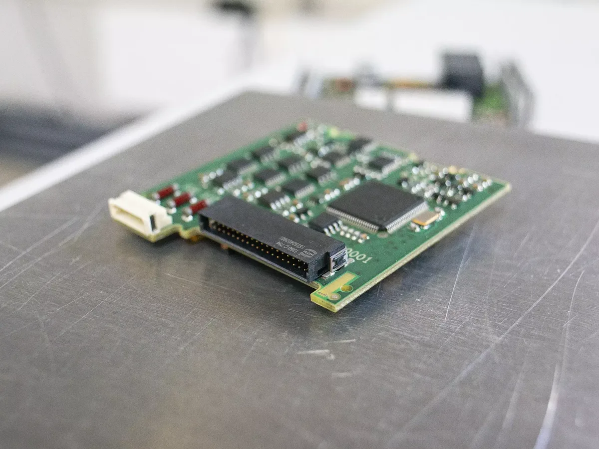
Plan board-to-board connection density with har-flex for the application
The HARTING har-flex family offers a miniature system approach for connections between boards, as well as between some boards and cables in industrial devices. The portfolio includes signal, data, power, and hybrid options; various contact counts, straight or angled configurations, and – in suitable products – SMT or THR mounts are available. At the family level, HARTING’s high-speed variants support data transfer rates of up to 25 Gbit/s. However, this maximum value does not mean that every har-flex connector can achieve 25 Gbit/s in any board layout. The pin layout, differential pair configuration, PCB material, line impedance, via connections, and the matching complementary components must all be carefully verified.
A hybrid configuration can combine power and signals in one interface. For example, product number 15 75 836 2601 333, har-flex Hybrid M ang 8+36 SMT PL1 Sample is listed on HARTING’s website as an angled SMT connector with a total of 44 contacts; the contact configuration is specified as 8+36. This example demonstrates the layout logic within the hybrid family of products. For detailed information, refer to the data sheet of the specific series product to be ordered, which is applicable for current, voltage, complementary components, and production packaging applications.
Another specific power connector example, product number 15 55 012 2701 333, is har-flex Power M ang 12P THR PL1 Sample is available with 12 contacts, an angled geometry, THR mounting, and a nominal current of 19 A. The term “Sample” is part of the product name; packaging details, minimum order quantities, or alternative order numbers for mass production will be confirmed during the quotation process. The 19 A rating cannot be applied to the entire har-flex family or to products with a different number of contacts. The PCB copper design, consideration of ambient temperatures, the calculation of multiple-contact loads, and derating factors must all be based on the actual operating conditions of the device.
har-flexicon: field-wirable PCB interfaces
har-flexicon is a family of HARTING terminals and plug-in connectors designed specifically for connecting individual field conductors to PCBs. The manufacturer introduces the 1.27 mm pitch as the smallest option in this family; other pitch options such as 2.54 mm, 3.5/3.81 mm, and 5.0/5.08 mm also meet various requirements for different cross-sections and connection configurations. The smaller pitch allows for a higher connection density; however, parameters such as conductor cross-section, current capacity, voltage rating, insulation thickness, and accessibility for maintenance are determined on a product-by-product basis.
The portfolio includes various termination options suitable for production, such as IDC connectors, push-in spring-loaded connectors, and screw-type field connectors, all available on the PCB side. Features like additional SMT holders, active locking mechanisms, and packaging designed for automatic placement must be confirmed for the specific variant. With a plug-and-play design, the electronic circuit board can be replaced without disconnecting the field cable. To ensure proper installation, the plug-header compatibility, number of pins, orientation, and anti-misassembly coding are clearly defined.
Specific examples illustrate the differences between product codes. Product number 14 13 021 4001 000, har-flexicon 3.50 MWV-2, is listed as a vertical header with two contacts and an 11 A rating. Product number 14 31 021 3101 000, har-flexicon 2.54 FPV-2 , is a vertical Push-In spring-cage connector with two contacts and a 6 A rating. Product number 14 31 061 7102 000, har-flexicon 5.08 FPH-6 , is horizontal with Push-In spring-cage termination, six contacts, and a 12 A rating. Product number 14 31 031 7401 000, har-flexicon 5.08 FSV-3 is specified as vertical, screw-terminal, three-contact type, with a current rating of 15 A. These values are applicable only to the respective products mentioned; the load per pole, environmental conditions, and PCB layout are calculated in accordance with the current specifications.
har-modular: customisable PCB connectors
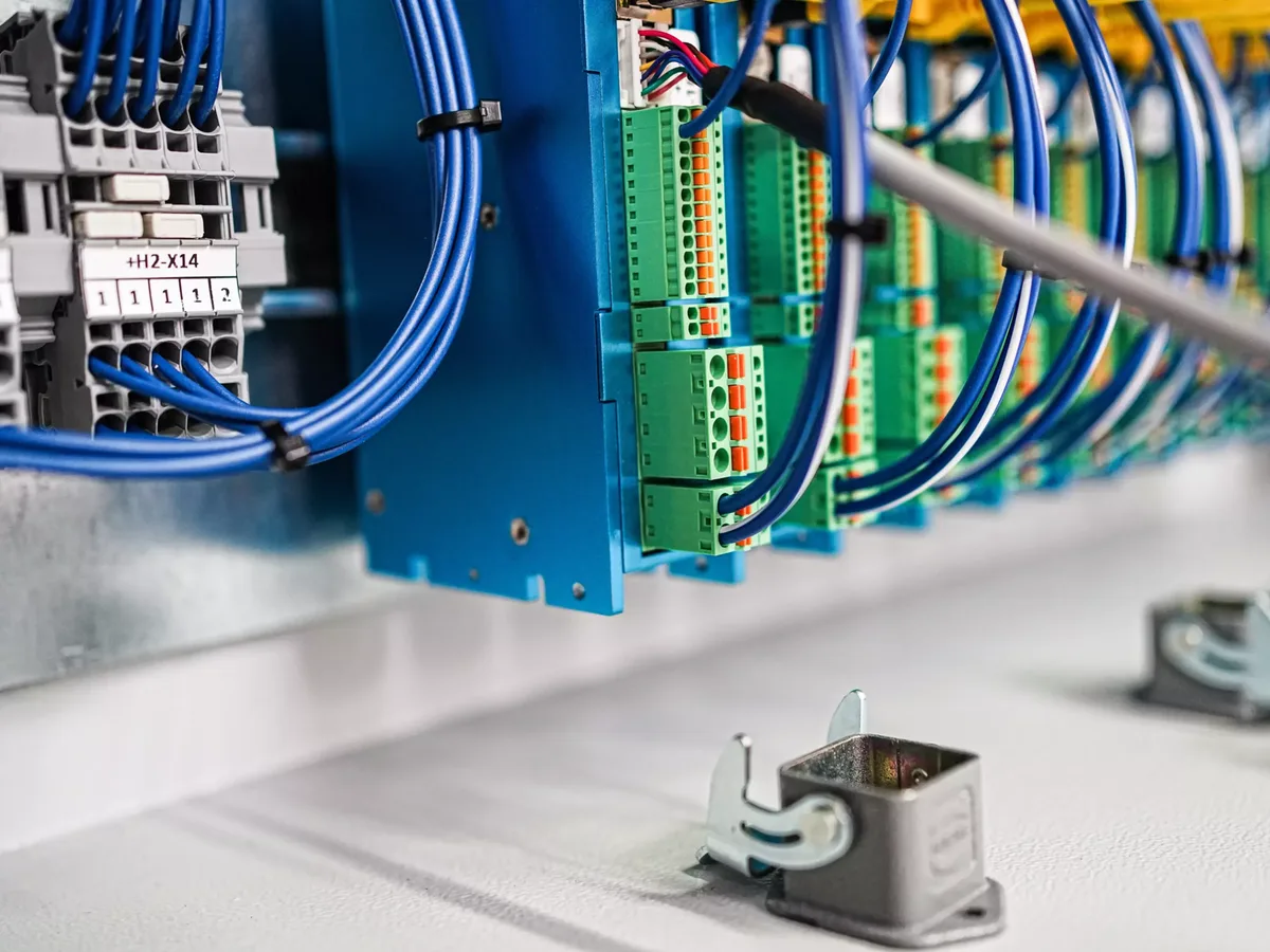
har-modular is a modular PCB connector approach designed to combine signal, data, and power contacts as needed. Rather than using a fixed pin layout, the required modules can be arranged on the carrier. This design enables the establishment of a common mechanical interface across different device variants and helps minimize the amount of unused contact space. However, modularity does not mean that electrical and mechanical specifications can be disregarded; the carrier length, module arrangement, counterpart components, hole pattern on the circuit board, and matching tolerances are all essential parts of the configuration process.
In the close proximity of power supplies and high-speed data transmission channels, thermal behavior, insulation properties, and signal integrity must all be taken into consideration simultaneously. The CAD data of the modular connector must be transferred to both the PCB and the device’s enclosure; the layout of the circuit board should include keep-out zones, solder pads, holes, and mechanical supports as required. The order number and revision level of the configured product must be clearly documented in the material list. HARTING’s online tools can simplify the design process; however, the final performance of the system must still be verified using the actual circuit board, cables, and corresponding interfaces.
HARTING ix Industrial: compact industrial Ethernet interfaces
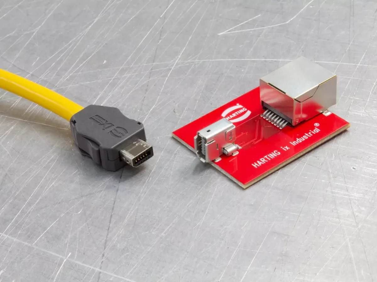
HARTING ix Industrial is a compact industrial Ethernet interface that complies with the IEC 61076-3-124 standard. HARTING claims that this product family is up to 70% more compact than traditional RJ45 connectors and is capable of data transfer rates of up to 10 Gbit/s. Additional features include 360-degree shielding and high resistance to industrial vibrations and impacts. These statements represent the manufacturer’s comparisons of this product family to traditional designs. The data transfer speed and EMC performance of a specific device port must be verified through tests regarding the selected connectors, cables, PCB traces, chassis mounting, and protocol compatibility.
Product number 09 45 281 2561, ix Industrial 10A-1 jack AH (T&R550) is an example of a specific configuration. The official product page describes it as a jack with horizontal soldering connections, A-code labeling, eight signal contacts, and two ground contacts, capable of handling a nominal current of 1.5 A. The “T&R550” packaging indication refers to its tape-and-reel packaging format, which should be taken into account when planning automatic assembly. The component footprint, soldering profile, and matching cable connector for this product must all be selected from the same official documentation.
The fact that an interface is designed for industrial use does not necessarily mean that its exposed jack connectors automatically possess a high level of IP protection. The device’s environmental protection capabilities must be assessed separately with regard to the jack design, the transition between the connector body and the surrounding structure, the gasket, the mating plug, the locking mechanism, and the open/closed state of the connector. The low-impedance connection between the cable plug and the PCB or the device’s chassis must be carefully designed; the signal ground should not be connected in a random manner. In the case of communication applications that use coding systems such as A and B, this must be verified in conjunction with the corresponding matching components.
PCB termination technologies: THT, THR and SMT
Through Hole Technology (THT) relies on passing the component pins through plated through-holes in the circuit board and connecting them using wave soldering. Hole diameter, pin geometry, copper plating, solder filling, and circuit board thickness are all critical factors affecting reliability. In connectors that handle mechanical loads, THT soldering can provide robust fixation; however, the actual strength depends on the circuit board design and the soldering process. For components with large bodies, mechanisms for support and heat dissipation are also necessary.
Through-Hole Reflow Soldering (THR), also known as pin-in-paste, inserts contact pins into plated through-holes for soldering during the reflow process. HARTING emphasizes that suitable THR components can be processed using pick-and-place techniques. The volume of the solder paste, the stencil aperture, the hole/pin ratio, the component’s temperature resistance, and the reflow profile are all determined based on the specific application requirements of the product. The presence of the “THR” designation in a product name does not imply that all available reflow profiles are suitable for that product.
Surface Mount Technology (SMT) solders pins to the pads on the board surface. These solutions offer fine pitch and are suitable for automated production. To prevent the mating and disengaging forces of the connector from being transmitted solely to the solder joints, relevant products may include metal retaining elements or other fixing mechanisms. The pad geometry, stencil design, packaging orientation, vacuum pickup surface, mounting forces, reflow profile, and optical inspection criteria must all be aligned with HARTING’s footprint and process specifications.
| Connection requirement | HARTING approach to consider | Key information to verify against the product code |
|---|---|---|
| Compact signal connection between two cards | har-flex signal or the appropriate high-speed variant | Number of contacts, card orientation, stacking height, data requirements, SMT/THR, and related products. |
| Power and signals on the same card interface | har-flex power/hybrid or har-modular configuration | Contact layout, current derating, insulation, module arrangement, and mechanical support. |
| Direct connection of the field conductor to the PCB | har-flexicon terminal or plug-in connector | Pitch, conductor cross-section, Push-In/screw/IDC, pole count, cable direction, and current/voltage |
| Compact industrial Ethernet port | HARTING ix Industrial jack and corresponding plug | A/B coding, data speed, cable, screen, footprint, soldering process, and environmental protection. |
| Automated PCB manufacturing | SMT or THR variants in suitable packaging. | Tape-and-reel/tray systems, contact surfaces, orientation, pads/holes, stencils, and reflow profiles. |
| Fast card replacement in service applications. | Detachable board-to-cable connection or pluggable terminal | Locking, coding, mating cycles, cable strain relief, and operator access |
Assess electrical ratings under actual operating conditions
The nominal current value specified in the catalog does not mean that all contacts within the device can handle the same load at any temperature. Ambient temperature, the number of contacts, power lines connected in parallel, the copper area of the circuit board, and heat generation due to poor ventilation all affect the operating conditions. The operating point should be determined based on the manufacturer’s derating curve and the measurement conditions specified by the relevant standard. The allowable local temperature for components such as processors, sensors, or data lines located near power connectors must also be taken into consideration.
When selecting a voltage level, factors such as the degree of contamination, the overvoltage category, the altitude, as well as the creepage and clearance distances on the PCB are important considerations. The permitted distance between connector contacts does not compensate for any errors in the layout of the circuit traces on the board. If different voltages are present on the same hybrid interface, the isolation areas and potential error scenarios must be carefully defined. The protective conductor or the functional ground contact is typically depicted in the schematic as a separate circuit component, distinct from the mechanical contact points.
Signal integrity and EMC verification
In a high-speed data channel, the connector is merely a component of the entire transmission path. The differential pairs are routed on the PCB to achieve the desired impedance; factors such as the length mismatch within each pair, the number of vias, any interruptions in the reference plane, and the geometry of the connection to the connector must all be carefully controlled. Both the cable and its counterpart connector must meet the same category/protocol specifications. The highest data speed specified on the product page does not compensate for poorly designed circuit connections or incompatible cables.
Shielding requires that the cable shield be terminated with appropriate contact areas at the device interface and properly connected to the chassis structure. A long, thin pigtail connection may reduce the shielding effectiveness required at high frequencies. ESD, EFT, surge, and immunity tests must be conducted in accordance with relevant device standards. Preliminary compatibility tests help identify potential issues with the layout and shielding design before the circuit board is finalized.
Mechanical life, servicing and manufacturability
The values for mating cycles, vibration, and shock must be verified in accordance with specific product and testing standards. board-to-board connectors may be aligned via the device cover or via screw connections; it should not be assumed that the connector alone is capable of withstanding all mechanical stresses. Guidance features, polarization requirements, and mounting tolerances help prevent incorrect alignment. On the cable side, strain-relief measures help reduce the transfer of stress to the solder joints during maintenance or service.
For mass production, the product’s packaging format—whether in tape and reel, trays, or some other type—must be matched to the processing capacity of the assembly machine. The fact that identical products may use different shipping packages does not mean they require the same assembly procedures. On the first assembled board, inspections are conducted for soldering, bridging, tombstoning, coplanarity, and mechanical stability. The quality control plan may specify additional tests such as cross-section analysis, X-ray inspection, or functional testing for internal connections that cannot be detected by automated optical inspection methods.
Quotation checklist for interface and PCB connectors
- Define the function of the interface: Specify board-to-board, board-to-cable, or field terminal connections, and identify power, signal, and data channels separately.
- Provide the board geometry: Provide the card thickness, the orientation of the two cards, the stacking height, the device edge, the panel opening, the keep-out areas, and the respective tolerances.
- Write down the electrical load: Specify the current, voltage, signal type, data rate, impedance, and insulation requirements of each contact group.
- Describe the cable: Record the number of conductors, cross-section, shielding, outer diameter, bending radius, as well as the requirements for movement and strain relief.
- Select the PCB process: SMT, THT, or THR; match the lead-free solder profile, stencil, wave soldering process, and cleaning procedures with the production line requirements.
- Determine the field connection: When selecting between push-in connectors, threaded connectors, IDC connectors, crimped connectors, or pre-assembled cable assemblies, consider factors such as installation space requirements and maintenance accessibility.
- Describe the environment: Separate the requirements regarding temperature, humidity, dust, water, chemicals, vibration, shock, ESD, and EMC at the product and device levels.
- Assemble the matching components: Show header, plug, jack, contact, locking mechanism, coding, cover, and cable accessories in the complete product tree.
- Establish a verification plan: Plan for derating, signal integrity, EMC compliance, environmental factors, mechanical cycles, solder quality, and functional testing before proceeding with the prototype development.
- Request the latest data: Verify the technical specifications, CAD/ECAD models, PCB footprints, packaging details, and processing instructions for the selected order number.
Once this information is available, HARTING interfaces and PCB connectors can be evaluated not only based on the number of contacts and external dimensions but also throughout the entire life cycle of the device. Oskon can integrate data on the electronic circuit board, cable harness, mechanical design, and manufacturing process within the same product database, thereby ensuring that the correct matching components are included in the quotation. The availability of the products, delivery times, and their suitability for a particular application must also be confirmed at the time of quotation; such information does not constitute any warranty regarding stock levels or performance.