Machine safety is not merely the selection of a single component, such as a yellow-colored sensor. It requires the identification of hazards, the assessment of risks, the determination of necessary safety functions, the selection of appropriate detection devices and safety logic systems, the reliable cessation of hazardous movements, and the verification of the entire safety chain. Even when fixed machines, robot cells, conveyor sections, and mobile robots operate in the same workspace, different protection mechanisms are required depending on factors such as approach speed, access routes, stopping times, and the potential consequences of failures.
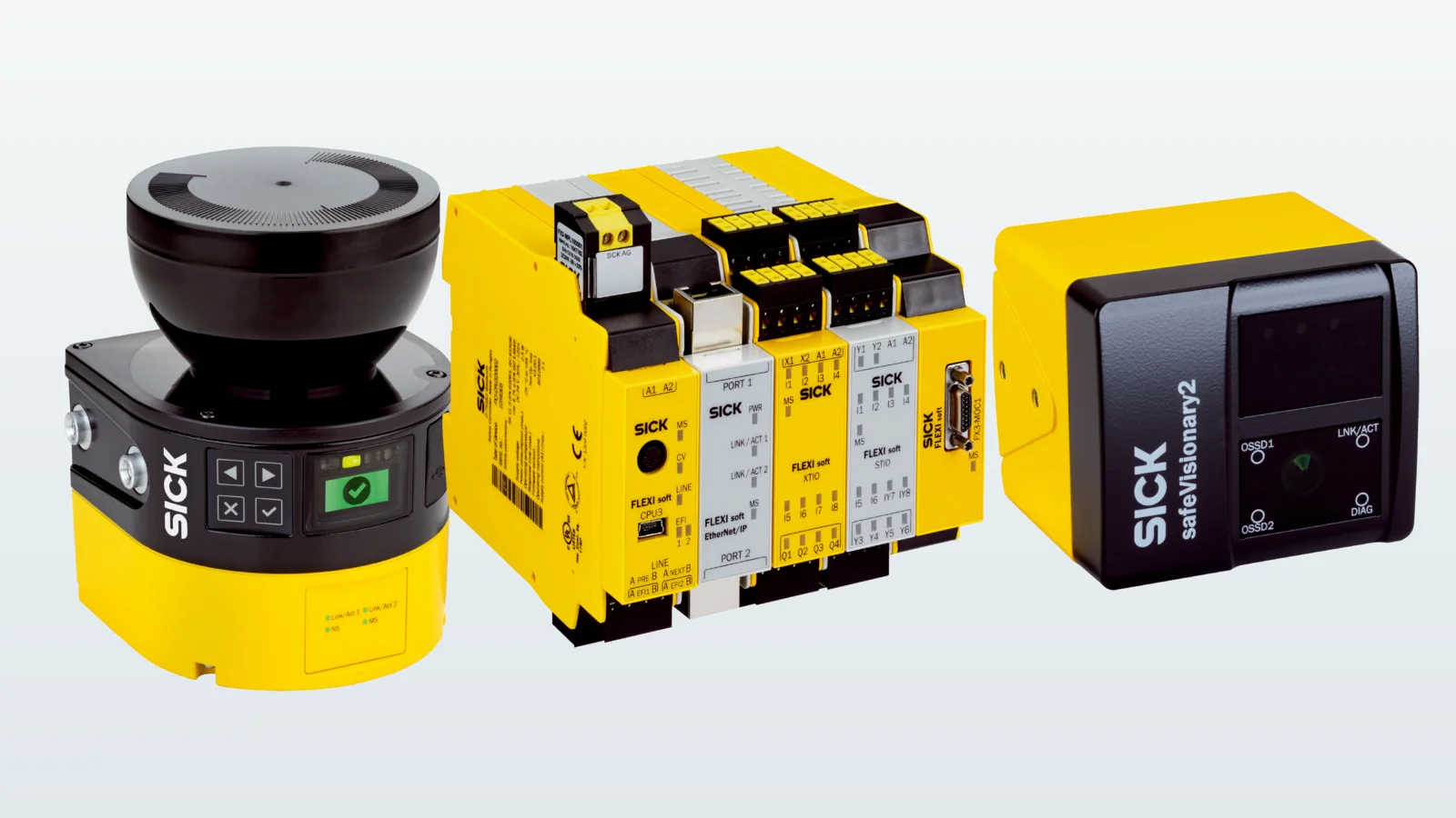
This catalog and project guide uses the SICK microScan3 safe laser area scanner, Flexi Soft safety controller, and safeVisionary2 safe 3D camera as concrete examples illustrating their various applications. The fact that these products can be used together does not mean that every application necessarily requires all three components. The appropriate solution should always begin with a thorough risk assessment; the required performance level, SIL classification, response time, protection area, and safe output functionality must be confirmed based on the latest documentation for the selected product model.
Define the safety function before selecting products
The statement “The machine must stop if someone enters the area” represents a basic requirement, but it does not constitute a verifiable safety function. It is essential to clearly define from which direction access to the area is permitted, at which point detection occurs, how quickly dangerous movements are halted, how restarts are prevented, and what the safe conditions in the event of a malfunction are. The protection zone must cover access not only during operation but also during setup, cleaning, mold change, maintenance, and troubleshooting procedures.
The required safety performance is assessed for the entire subsystem. The fact that a sensor possesses high performance or a high SIL rating does not in itself prove that all components—including wiring, safety logic, contactors, drives, and mechanical design—have reached the same level of safety. In system design, factors such as common cause failures, test coverage, diagnostic capabilities, operational reliability, and component data must also be taken into account. The implemented solution must be verified by qualified personnel in accordance with relevant standards and local regulations.
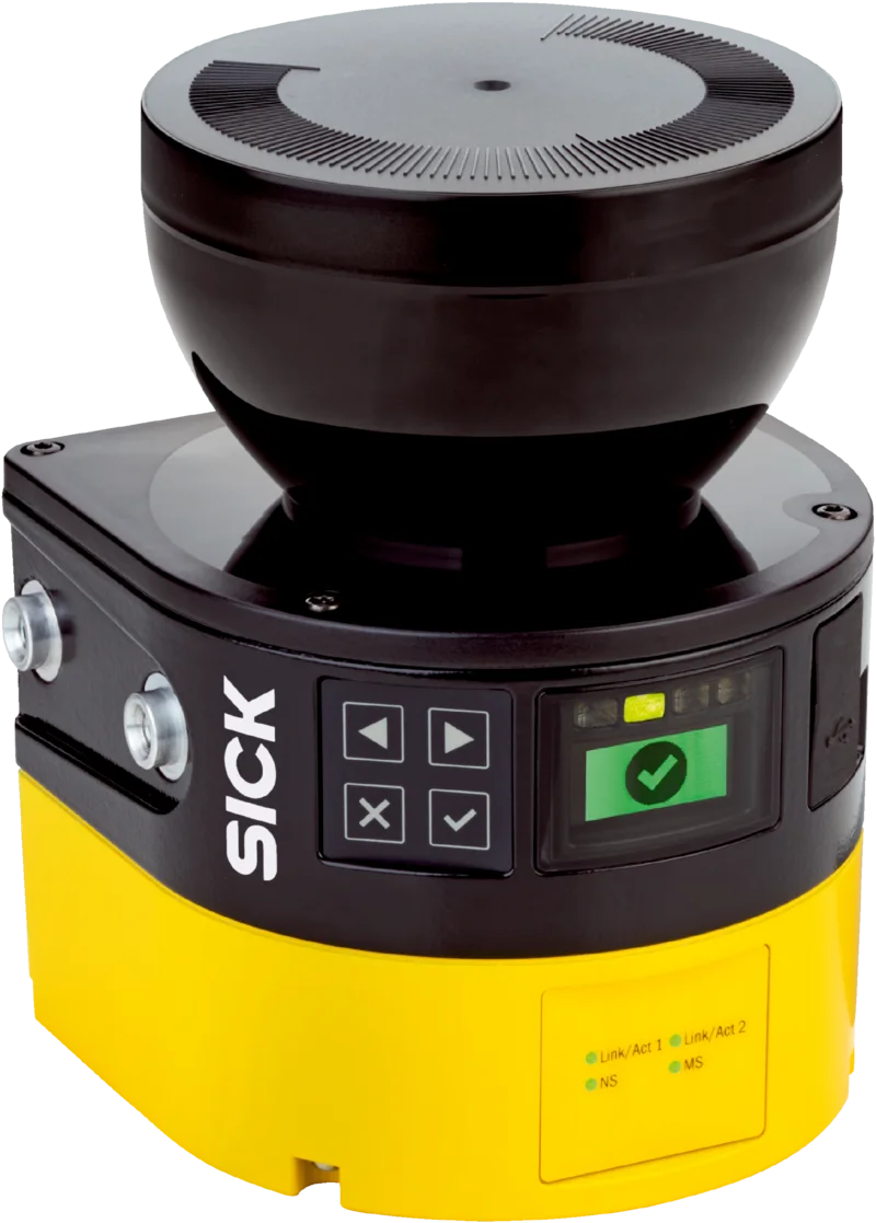
microScan3: configurable two-dimensional area protection
The SICK microScan3 family consists of safe laser area scanners used to create horizontal or vertical protection zones in both fixed and mobile applications. The official product page lists the safeHDDM scanning technology, a 275-degree scanning angle, a protection zone range of up to 9 meters, 128 freely configurable zones, and the ability to monitor up to 8 protection zones simultaneously for this family of products. It should be noted that these maximum values vary across different models; the range, number of zones, connectivity options, and safety features of the Core, Pro, and network-enabled versions must be checked individually.
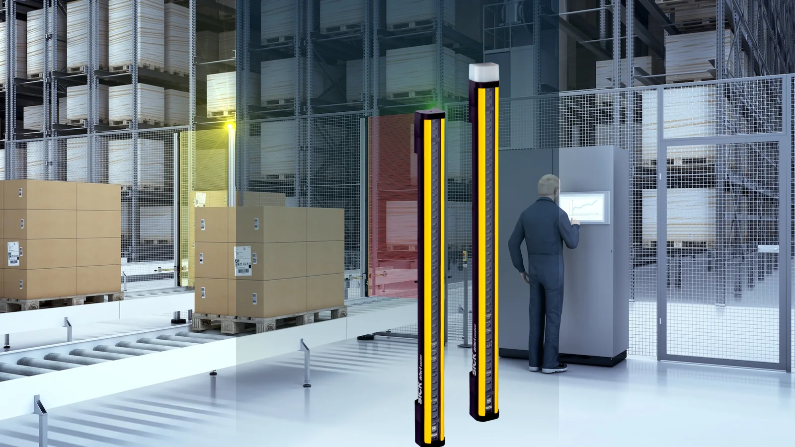
A laser scanner can detect the approach of a person in cases where protection is required in a horizontal area near the ground, or detect attempts to access a restricted zone or violate its boundaries in vertical installations. For mobile robots, different protection zones can be selected based on the current speed and direction of movement. However, the scanner itself does not constitute a mechanical barrier. Additional protection measures are necessary if it is still possible to approach the hazardous area from above, below, or behind the scanning area. Factors such as blind spots, columns, the possibility of the load shifting, the braking distance of the robot, and any differences in ground levels must be taken into consideration when planning the layout of the area.
Distinguish protective and warning fields by function
A warning field can support productivity by requesting speed reduction or giving visual/audible warnings during approach. Infringing the protective field triggers the safety function; the warning field cannot replace it. Mobile applications may require longer protective fields at higher speeds or different field sets for each direction. Validate field switching signals, sequence, and unexpected combinations in the safety logic.
The safeHDDM technology of the scanner is highlighted on the product page as offering robust performance in the face of factors such as dust and ambient light. However, this does not imply unlimited environmental immunity. Conditions such as dirt on the optical cover, heavy condensation, physical objects blocking the view, incorrect installation, or light levels outside specified limits must still be taken into consideration. The installation location should be protected from impacts, vibrations, and dirt; diagnostic messages should be integrated into the maintenance routine.
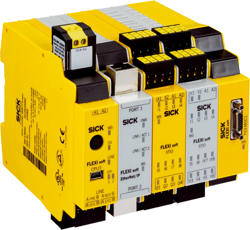
Flexi Soft: the logic layer between sensors and safe motion
Flexi Soft is a modular safety controller in SICK’s product portfolio that can be programmed using software. The main modules—digital and analog input/output modules, network gateways, Motion Control components, and relay modules—can be combined according to specific application requirements. The system’s socket allows for the storage of configuration data, and the license-free Flexi Soft Designer software supports device configuration and replacement within the same family. The number of required modules and channels, as well as the synchronization of safety functions, are determined based on the specific communication network being used.
The safety controller is capable of logically combining signals from emergency stop devices, door locks, light curtains, or area sensors and converting them into safe output signals. However, the programmed logic cannot replace a thorough risk assessment. Functions such as reset conditions, restart locks, operating mode selection, maintenance bypass, and muting must be designed and tested to prevent unauthorized manipulation. If a mode selection bit from a standard PLC is used for safety decision-making, the reliability of the corresponding signal must also be verified.
Network, series connection and motion monitoring decisions
According to SICK’s product page, Flexi Line is a family of products that supports the safety network connection of up to 32 Flexi Soft stations, while Flexi Loop enables the serial connection of up to 32 safety sensors. These numbers depend on the appropriate hardware and configuration settings. Serial connection can reduce the number of cables required; however, the detailed diagnosis of each device, the overall response time, the length of the cables, and the fault behavior must be calculated based on the product documentation. A standard field data link and a safety protocol are not the same thing.
In the Safe Motion approach, information regarding speed, direction, or position can form part of the safety function. The mechanical connection of the encoder, the variety of signals it generates, the functionality of the drive, and the control logic must all be verified. Simply copying the standard speed data to the safety input is insufficient. In a network-based solution, the safety communication protocol, compatible device versions, network update timing, and the device’s behavior in the event of a connection loss must all be thoroughly tested.
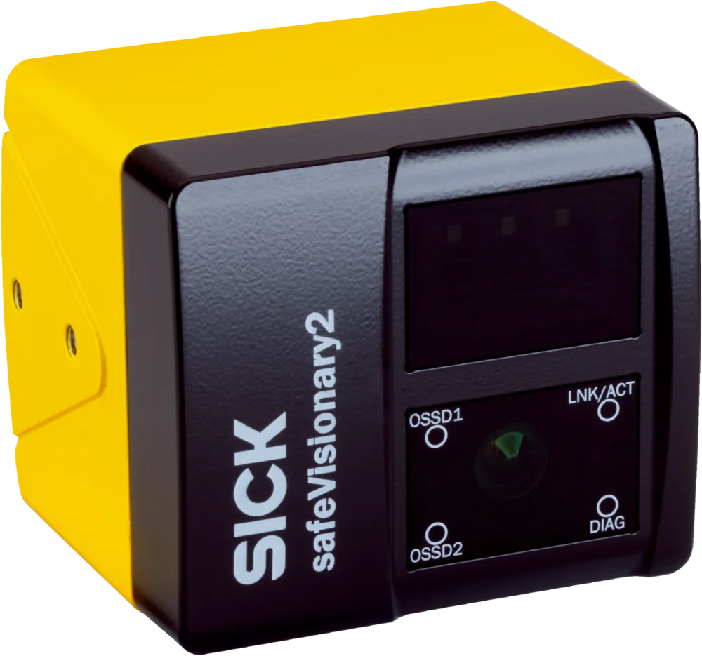
safeVisionary2: safe three-dimensional environment sensing
safeVisionary2 is SICK’s range of safety-certified 3D Time-of-Flight cameras. The official product page lists its performance level as PL c, a protection range of up to 4 meters, two simultaneous protection zones, eight monitoring modes, the ability to transmit measurement data via Gigabit Ethernet, and IP65/IP67 enclosure specifications. The same page also provides information stating that the camera can generate 30 images per second at a resolution of 512 × 424 pixels, and has dimensions of 70 × 80 × 77 mm. These values should be confirmed on the data sheet for the specific model selected, as well as in the product’s operating specifications.
Three-dimensional sensing can help a mobile robot detect protrusions above the laser scanning plane, monitor potential risks such as tilting or stretching within the robot’s movement range, and identify fall hazards with an appropriate design. The camera can also provide data on distance and intensity for automation purposes. In software, the functions of safety-related outputs and standard measurement data must be clearly distinguished; the presence of automation data does not necessarily imply that each data point has been verified for safety compliance.
Which technology suits each protective geometry?
| Project situation | SICK approach to consider | Critical verification |
|---|---|---|
| Horizontal hazardous areas in the machine environment | microScan3 configurable protection zone | Scanning plane, access, range, resolution, and total stopping time |
| Mobile robot with variable speed and direction control. | microScan3 field sets and suitable safety control | Braking distance, area transition logic, load protrusion, and ground conditions. |
| Multiple sensors and various operating modes | Flexi Soft modular safety controller | Input/output architecture, logic, response time, reset functions, and diagnostic capabilities. |
| Obstacles above the scanning plane | safeVisionary2 3D protection zone | Field of vision, blind spots, reflection, installation, and required performance levels. |
| Access and residual risk in a robot cell | Combination of two- or three-dimensional sensing technology with safe logic systems. | Risk assessment, safe distance, restart, and verification tests |
Measure safety distances and stopping times before defining the layout
The distance between the protective device and hazard must ensure that hazardous motion stops before a person can reach it. Total response time includes the sensor, safety logic, communication, output devices, drive, and mechanical stopping time. The sensor’s catalog response time alone is insufficient. Measure actual stopping time at the worst load, speed, and temperature, allowing for tolerances and wear.
Drawing the scanner area on the screen does not automatically ensure a safe physical distance. The scale, reference contour, mounting height, resolution, and additional protection zones must be implemented in accordance with the manufacturer’s instructions. For cameras as well, the volume limits must correspond to the actual machine coordinates. In the event of any escape or hiding areas outside the protection zone, the visibility of the reset point must be taken into account, along with additional detection systems and mechanical measures.
Commissioning, validation and change management
Before commissioning, the electrical schematic diagram, the list of safety functions, and the software configuration must all be updated to the same version. Each input is tested individually to ensure that the desired output state is safely achieved and that no unexpected modes are activated. The physical boundaries of the system are verified using appropriate test fixtures. Prescribed fault scenarios, such as power outages, network interruptions, sensor removal, short circuits, or cross-connections, are executed in accordance with the test plan.
Configuration files must be stored with access controls and version numbers in place. Unauthorized parameter modifications must be prevented; maintenance personnel should only be granted access to diagnostic data and no authority to modify the safety programs. If the sensor location, machine braking system, drive firmware, or product load changes, it cannot be assumed that previous validations are still valid. The affected safety functions must be re-evaluated, and the results recorded.
During periodic inspections, the optical surface, brackets, cables, protective areas, and stop functions are examined. Diagnostic records may indicate recurring issues such as contamination, vibration, or communication problems; however, the absence of error records does not eliminate the need for a physical test. The testing interval is determined based on risk assessment, manufacturer instructions, frequency of use, and relevant regulations.
Project data required for a quotation
- List the dangers: Describe the scenarios of movement, jamming, crushing, cutting, collision, and falling in terms of their respective operating modes.
- Define the safety functions: Specify the triggering event, the safe response action, the reset conditions, and the desired performance level.
- Share the layout: Indicate the access directions, blind spots, obstacles, mobile routes, and mounting surfaces in detailed drawings.
- Provide stopping data: Record the measured stopping time, speed, load, and braking behavior under the worst conditions.
- Provide the control architecture: Define the safety PLC, drive, contactor, network protocol, I/O components, and the energy-cutting circuit.
- Specify the environment: List the effects of dust, ambient light, vibration, impact, temperature, water, chemicals, and external environmental factors.
- Develop a test plan: List the scenarios of normal operation, maintenance, restart, power and network failures, as well as fault injection.
Oskon’s approach is to consider sensors and controllers not as separate components, but as elements of a verifiable safety function. The implementation is completed through thorough risk assessment, calculations in accordance with relevant standards, the selection of the appropriate product variant, safe machine responses, and documented validation processes. This guide does not constitute a risk assessment or conformity declaration in itself; the availability of the product and the scope of the project are also confirmed at the time of the offer.
Official technical resources
- SICK – Portfolio of industrial safety products
- SICK – microScan3 safe laser area scanner
- SICK – Flexi Soft safety controller
- SICK – safeVisionary2 safe 3D camera
The maximum range, number of zones, interface type, protection class, and safety performance may vary depending on the model and order code. The final design must be verified in accordance with current operating instructions, safety regulations, and application-specific validation procedures.