Servopneumatic positioning combines the ability of compressed air to generate precise and robust movements with closed-loop measurement and control systems. The goal is not merely to move a standard cylinder between two predetermined positions, but rather to move the load to specified intermediate positions, control the motion profile, or regulate the applied force in appropriate applications. A successful solution integrates the actuator, displacement measurement, proportional direction control valves, axis controllers, mechanical guidance systems, and air preparation components into a single system. This catalog guide provides a step-by-step approach, using Festo’s latest servopneumatic product range, from component selection to commissioning and acceptance testing.
What changes with a servopneumatic system?
In a traditional pneumatic system, a directional control valve pressurizes one of the two chamber compartments, and the final position is determined primarily by mechanical limits. In a servopneumatic system, the position of the actuator is continuously monitored. The controller analyzes the difference between the set target value and the actual measured value, and accordingly adjusts the position of the proportional valve’s spool. This adjustment gradually modifies the flow of fluid entering and leaving the cylinder chambers. As a result, the behavior related to acceleration, deceleration, and approaching the target position can be controlled not only by fixed-throttle devices but also through a feedback-based control loop.
The compressibility of compressed air is both an advantage and an engineering limitation of this system. Mechanical contacts allow for more flexible operation; however, variations in load, pressure, line volume, and friction can affect the quality of control. Therefore, the selection of a servopneumatic system should not be based solely on its ability to replace electric actuators. It is essential to compare the application’s requirements in terms of precision, stiffness, response time, energy consumption, and safety, and to verify the suitability of the chosen solution based on its actual performance under real-world conditions.
Initial decision: which tasks suit this approach?
Long-stroke movements that require adjustment to various intermediate positions, stoppers that can be adjusted according to the height of different products, controlled pressing or compressing actions, dynamic load transfer, and precise end-position control are all tasks that can be effectively addressed using servopneumatic technology. In its current category descriptions, Festo identifies this technology as being particularly suitable for applications that require precise control over position and force. It also notes that this technology can be cost-effective in scenarios involving the handling of heavy objects. However, this statement alone does not constitute a definitive selection criterion. For each individual project, factors such as cycle time, stroke length, precision requirements, the need for compressed air, and overall ownership costs must all be carefully evaluated again.
When extremely high static stiffness, long-term position retention with very low energy consumption, automatic load transfer in the event of pressure loss, or process precision at the micron level are required, alternative drive technologies are also compared. Scenarios such as power interruptions in the vertical axis, hose ruptures, and valve failures are also examined. The fact that a controller is capable of performing positioning tasks does not mean that the machine can independently carry out functions such as safe shutdown or load holding.
System architecture: actuator, valve and controller
- Actuator with measurement system: It generates mechanical motion and informs the controller of the actual position of the slide or piston.
- Proportional directional control valve: It continuously switches between filling and emptying the two working chambers according to the control command.
- Axis controller: Processes position or force targets, evaluates feedback and manages motion profiles and diagnostics.
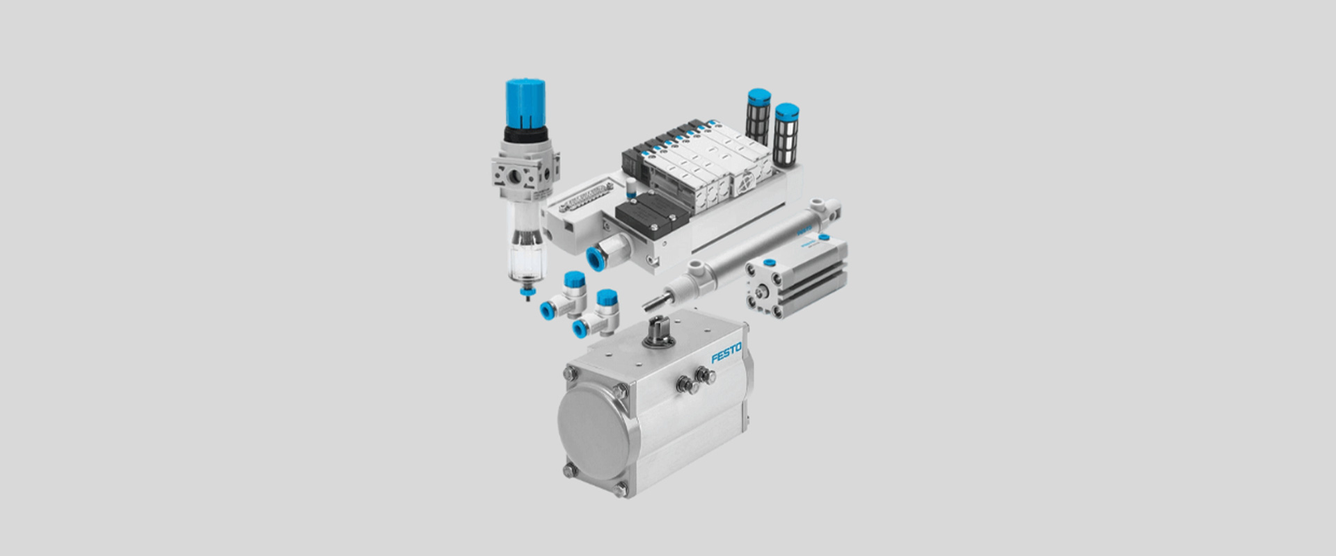
- Pneumatic infrastructure: Air preparation, feeding at the appropriate cross-section, and the use of suitable hoses and free exhaust ensure the creation of repeatable operating conditions.
- Mechanical and electrical components: The carrier structure includes guide rails, connection cables, sensors, the braking or clamping unit, as well as the high-level control interface.
It is not sufficient to consider only the nominal capacity of one of these components. If a small valve is connected to a large actuator, it will be difficult to achieve the desired time target; on the other hand, a large valve and long hoses may increase the volume of air that needs to be controlled. Even if the measurement resolution is high, flexible frames, loose connections, or variable friction factors can limit the actual precision of the process. System calculations must take into account both mechanical and pneumatic time constants.
DGCI: integrating measurement with the actuator
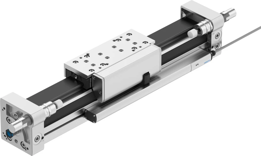
DGCI is a rodless linear-drive family with integrated displacement measurement. Festo highlights its absolute, contactless displacement encoder, guided construction and suitability for servopneumatic operation with CPX-CMAX or CPX-CMPX. The rodless architecture helps reduce overall machine length for long strokes. Check forces and moments on the carriage against guide capacity and mounting-surface accuracy.
In the current 2026 version of the DGCI technical documentation, the dimensioning and stroke options for this product family are provided in separate tables; these values do not remain constant for all possible combinations. Therefore, dimensioning cannot be based solely on the “DGCI” designation. The stroke length, piston diameter, guide option, measurement interface, pneumatic connection direction, and accessories must all be specified during configuration. The weight to be handled should include that of the gripper, adapter, cable-hose assembly, as well as the product in its heaviest configuration.
VPWP: metered flow control beyond simple on/off switching
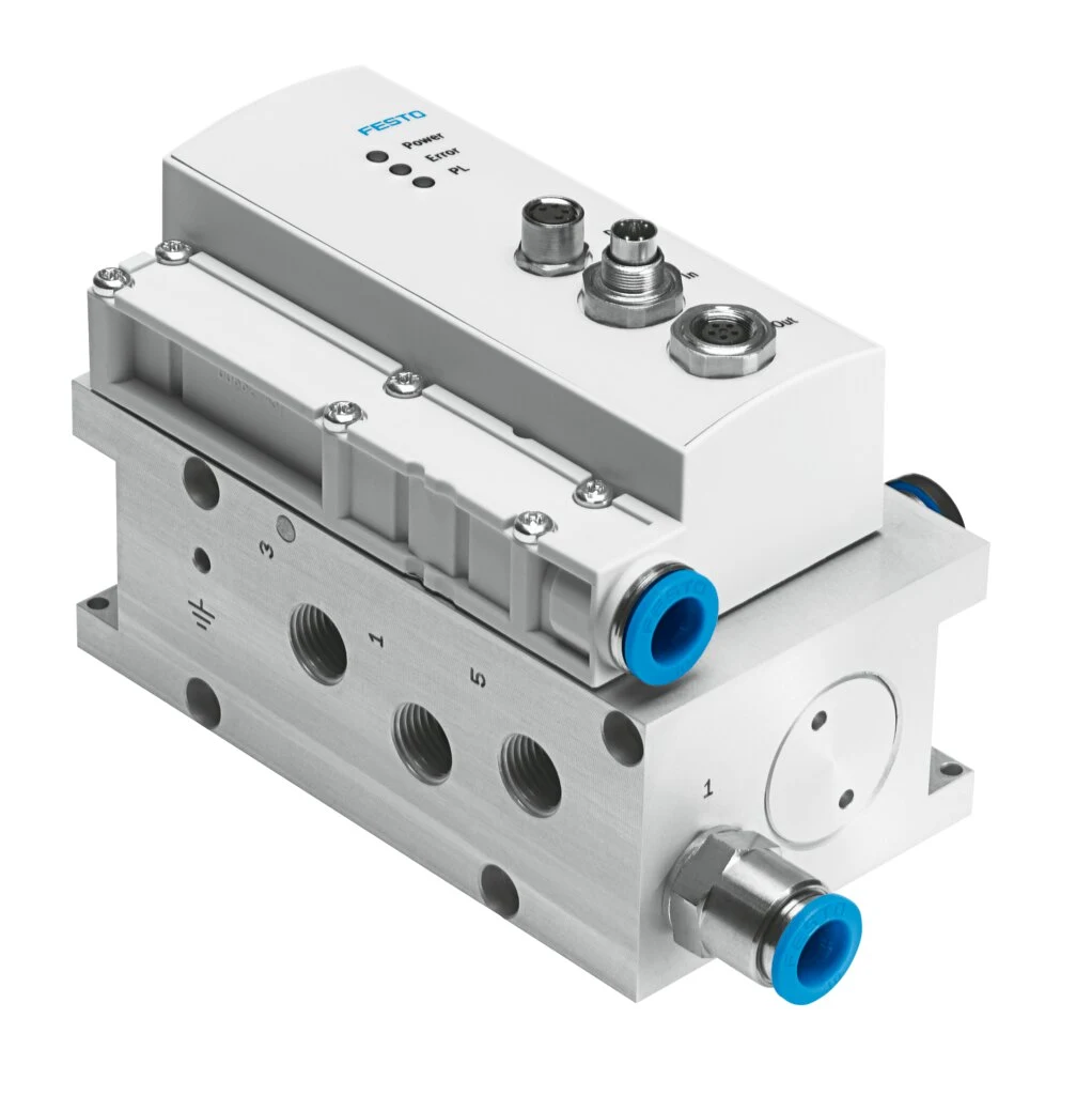
The VPWP is a digitally controlled, proportional direction control valve with a piston slide mechanism. According to the latest Festo product information, it features integrated pressure sensors, automatic identification capabilities, a diagnostic function, and a digital output that can be used for functions such as clamping or braking. It is explicitly stated that this valve can be used in servopneumatic applications in conjunction with the CPX-CMAX axis controller and the CPX-CMPX end-position controller.
The size of a valve cannot be determined solely based on the connection thread of its actuator. Factors such as the moving mass, cylinder volume, desired acceleration, stroke length, supply pressure, and hose length all affect the required nominal flow rate. Festo’s current product range offers various VPWP options with different nominal flow rates; the right choice should be determined through careful configuration calculations. Placing the valve in a position that best matches the actuator can help minimize unnecessary pipeline volume and delays. Additionally, issues such as contamination in the exhaust silencer or a small cross-section of the hose can also affect the valve’s cycle performance.
CPX-CMAX: coordinating position and force control
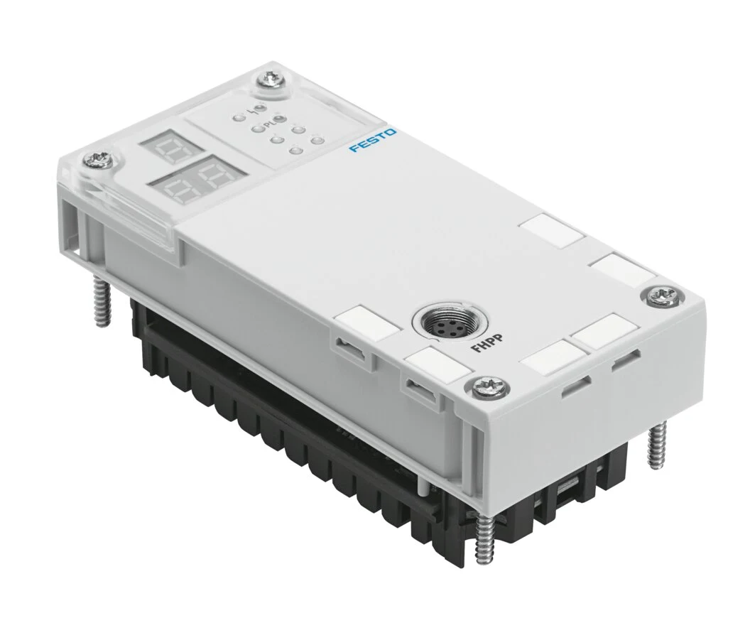
CPX-CMAX is an axis controller within the modular CPX electrical terminal. Product information describes support for rod-type, rodless and semi-rotary pneumatic drives, position and force control, automatic identification for commissioning, and diagnostics through Festo Configuration Tool. Axis control can therefore be integrated into distributed automation rather than remaining a standalone unit separate from field I/O.
The communication capabilities of the controller do not eliminate the need for a high-level PLC program. Machine status, recipe selection, target value limits, component availability, as well as door and safety conditions are defined in the interface between the PLC and the axis. The error code should not be displayed solely on the screen; instead, it should be recorded along with the timestamp, axis status, target value, actual value, and pressure conditions for maintenance purposes. The backup plan should also include the parameter settings and the version of software used.
The actual load profile required for sizing
| Input | Why is it required? | Common omissions in field specifications |
|---|---|---|
| Total moving mass | Determines acceleration, valve flow, braking and support loads. | Simply specify the product, while leaving the slide, holder, and cables unmentioned. |
| Stroke and target positions | It determines the length of the actuator, the volume of the line, and the sequence of cycles. | Only the maximum stroke is specified, without mentioning the frequently used short movements. |
| Movement time and waiting period | It affects the acceleration/deceleration profile and the energy requirements. | Regarding the entire machine cycle, it is mistakenly considered to be merely the time required for single-axis movement. |
| Mounting direction and external forces | Changes gravity effects, process forces and fault scenarios. | Failing to define vertical-load behavior after power loss |
| Precision and repeatability | The control target is aligned with the mechanical tolerance chain. | Treating measurement resolution as process accuracy |
| Air supply source | Dynamic pressure, flow and air quality affect control stability. | Assuming compressor pressure is the minimum pressure at the valve inlet |
Distinguish position control from force control
In position control, the main objective is to move the moving component to the designated position and maintain it within the specified tolerance range. In force control, the focus is on the force generated after contact with the target object. These two tasks can be carried out at different stages of the same cycle; for example, position control during the approach phase can be followed by force control after contact. The transition conditions, permitted speed, maximum force, contact detection, and time limits must be clearly defined.
Pneumatic force is related to pressure and the effective piston area; however, factors such as friction in seals, pressure in the opposite chamber, installation orientation, and mechanical losses can alter its actual value. The use of a controller’s pressure feedback does not necessarily mean that the process force can be measured directly and reliably in all situations. The measurement uncertainty required for quality monitoring must also be taken into account; when necessary, independent force sensors should be utilized.
Why are air preparation and piping control parameters?
The supply pressure is not merely determined by the static manometric value; rather, the lowest dynamic pressure occurring at the valve inlet when the shaft is accelerating must be measured. The total flow resistance of the main pipeline, filter-regulator unit, distribution block, valves, and hoses must also be taken into account. If other high-flow consumers are operating on the same pipeline, the test should be conducted under the most unfavorable simultaneous operating conditions. Increasing the pressure unnecessarily may not resolve the issue of insufficient cross-sectional area; instead, it could lead to increased energy costs and mechanical loads.
The inner diameter, length, and number of connections of the hoses affect the time required for the two chambers to fill and empty. Hoses of different lengths can result in asymmetric movement patterns. Hose damage, incorrect diameters in the connections, clogged mufflers, or dirty filters can all cause the control settings to change over time. The air quality must meet the current technical requirements of Festo components; the lubrication system must be consistently applied throughout the entire installation.
Mechanical installation and the measurement chain
Mount the actuator without mechanical stress using manufacturer-approved mounting components. For long strokes, assess profile supports, frame deflection and thermal expansion. Moment loads increase as the load’s center of gravity moves farther from the carriage; checking axial force alone is insufficient. Measure mounting tolerances where parallel guides could cause misalignment, binding or variable friction.
Protect the displacement sensor and connection cable from electromagnetic and mechanical influences. Route the cable in the cable carriers according to the manufacturer’s bending requirements, with strain relief near connectors. Define a tool offset when the measurement and process references differ. Include the part contact point, adapter deflection and gripper play in the actual acceptance target.
Commissioning sequence
- Control the mechanical connections, stroke range, pneumatic ports, cables, and movement direction under conditions of limited energy availability.
- Verify that the combination of actuator, valve, and controller is compatible according to Festo documentation, using the complete order codes as reference.
- Pressurize the air line under controlled conditions; measure the leakage rate, the condition of the filter, the exhaust opening, and the dynamic supply pressure.
- Verify at low speeds that the measured value is consistent with the direction of the mechanical movement and the actual stroke length.
- Perform automatic identification and basic parameter setting in accordance with the manufacturer’s commissioning instructions; record the resulting values.
- Test all target positions at the lightest, nominal, and heaviest loads, as well as short and long movements separately.
- If the system supports force mode, test scenarios involving contact, transition, limit reached, timeout, and lack of a component.
- Verify whether the pressure drop, sensor errors, communication interruptions, and post-emergency shutdown behaviors meet the requirements of the risk assessment.
Use the right metrics for performance acceptance
For production acceptance, it is not sufficient for a single axis to “reach the target position.” The position error must be measured separately when approaching the target in the same direction and in the opposite direction; repeatability should also be evaluated under different loads, temperatures, and supply pressures. Data on settling time, overshoot, cycle time, pressure consumption, and failure rate are recorded. If the process involves contact, the force curve and contact speed are also monitored. During long waiting periods, the impact of position or pressure adjustments on energy consumption and temperature is observed.
The test sample should not merely be a representative of the nominal product; the heaviest and lightest units must be compared, taking into account allowable variations in friction, as well as initial conditions at the start of each shift and thermal stability. The target tolerances should be determined based on mechanical measurements of the machine itself; the internal position values displayed on the controller screen cannot replace such independent measurements. Clearly defining the acceptance criteria, the measurement methods, and the number of samples to be tested during the contract negotiation phase can help minimize disputes during the commissioning process.
Safety, power loss and restarting
Servopneumatic control is a normal operating function; a safety function, however, can only be established through risk assessment, determination of the required performance level, and the use of approved component architectures. The consequences of pressure loss along a vertical or potential-energy-carrying axis must be carefully calculated. Measures such as mechanical holding, braking, counterbalancing, controlled exhaust, or moving the load to a safe area are selected based on the specific application. The fact that a digital output on the VPWP can control a braking or clamping device does not in itself constitute a valid safety certification.
When energy is restored, automatic operation must not be allowed without first verifying the axis’ reference position, the actual location of the component, and the status of other parts within the process area. Scenarios such as unexpected startups, stuck components, or the need for operator intervention are all programmed into the control software. During maintenance, both air and electrical energy are safely isolated; any stored pneumatic energy is released, and any moving components are mechanically secured.
Maintenance and lifecycle management
Regular maintenance is not limited to merely checking for seal leaks. It also involves monitoring parameters such as guide clearance, profile alignment, hose friction, connector looseness, filter blockages, pressure drops in the filtration system, and trends in dynamic supply pressures. If the number of control errors increases, mechanical friction, leaks, and pressure conditions should be inspected before making any changes to the software settings. Random adjustments to parameters may actually conceal the root cause of the issue.
The spare parts list should include the full product number, configuration details, and document version, rather than just the family name. Parameter backups, PLC interface definitions, cable lists, and pneumatic schematic diagrams should be stored alongside the machine documentation. Before placing an order, the product’s lifecycle and any recommended replacements should be verified on Festo’s current product page; a variant listed in an older catalog should not be assumed to be still available.
Information checklist for quotation preparation
- Direction of movement, mounting method, precise stroke length, intermediate targets, and mechanical end portions.
- The lowest/highest moving mass, including the slide, adapter, holder, product, cable, and hose.
- Target movement time, waiting time, cycles per hour, and operating profile.
- Required position tolerance, repeatability, settling time, and measurement method.
- Range of force, contact speed, process tolerance, and the need for independent measurement.
- The dynamic pressure of the system, air quality, available flow rate, and simultaneous users.
- Ambient temperature, dust, humidity, cleaning requirements, vibration, and protection needs.
- PLC, field network, CPX configuration to be used, error logging, and recipe management.
- Risk assessment, vertical loads, power outages, and restart scenarios
- Acceptance testing, documentation, training, spare parts and maintenance targets
A proper servopneumatic system is not defined by a single catalog code, but rather by a compatible combination of components and measurable acceptance criteria. DGCI represents motion and feedback control, VPWP controls air flow, while CPX-CMAX enables position/force control. In the Oskon approach, these three elements are verified in conjunction with the actual load profile, air supply system, machine safety features, and advanced automation capabilities. The final selection is always confirmed based on the latest Festo product specifications and the technical documentation for the specific variant to be ordered.
Official Festo resources
- Festo — The product category of servo-pneumatics
- Festo — DGCI: Linear drive with position measurement function
- Festo — VPWP proportional directional control valve
- Festo — CPX-CMAX axis controller
- Festo — DGCI Technical Documentation (Version 2026)
- Festo — VPWP technical documentation
- Festo — CPX-CMAX Technical Documentation