In an industrial distance measurement application, the main question is not merely “how many meters do we need to measure?” Instead, factors such as the color and reflectivity of the target surface, its movement speed, the required measurement accuracy, the presence of surrounding light, dust, or fog, the mounting angle, the communication method, and safety requirements must all be taken into consideration simultaneously. SICK distance sensors offer a range of options based on light, ultrasound, or radar technology, suitable for various tasks—from precise short-range positioning to long-axis positioning of warehouse cranes, from level monitoring to environmental detection of mobile equipment. The right choice depends not on the maximum range listed in the catalog, but rather on the ability to achieve consistent and reliable measurement results in the actual application.
What does a distance measurement sensor measure?
A distance sensor converts the distance between itself and the target into a digital or analog value in a non-contact manner. This value can be used to detect the presence of an object, or it can provide information regarding the object’s continuous position, thickness, diameter, fill level, sagging, stacking height, or axis of motion. While a photoelectric sensor only requires a “presence/absence” output, measurement sensors require additional performance criteria such as resolution, repeatability, linearity, response time, and the stability of the measured values over time.
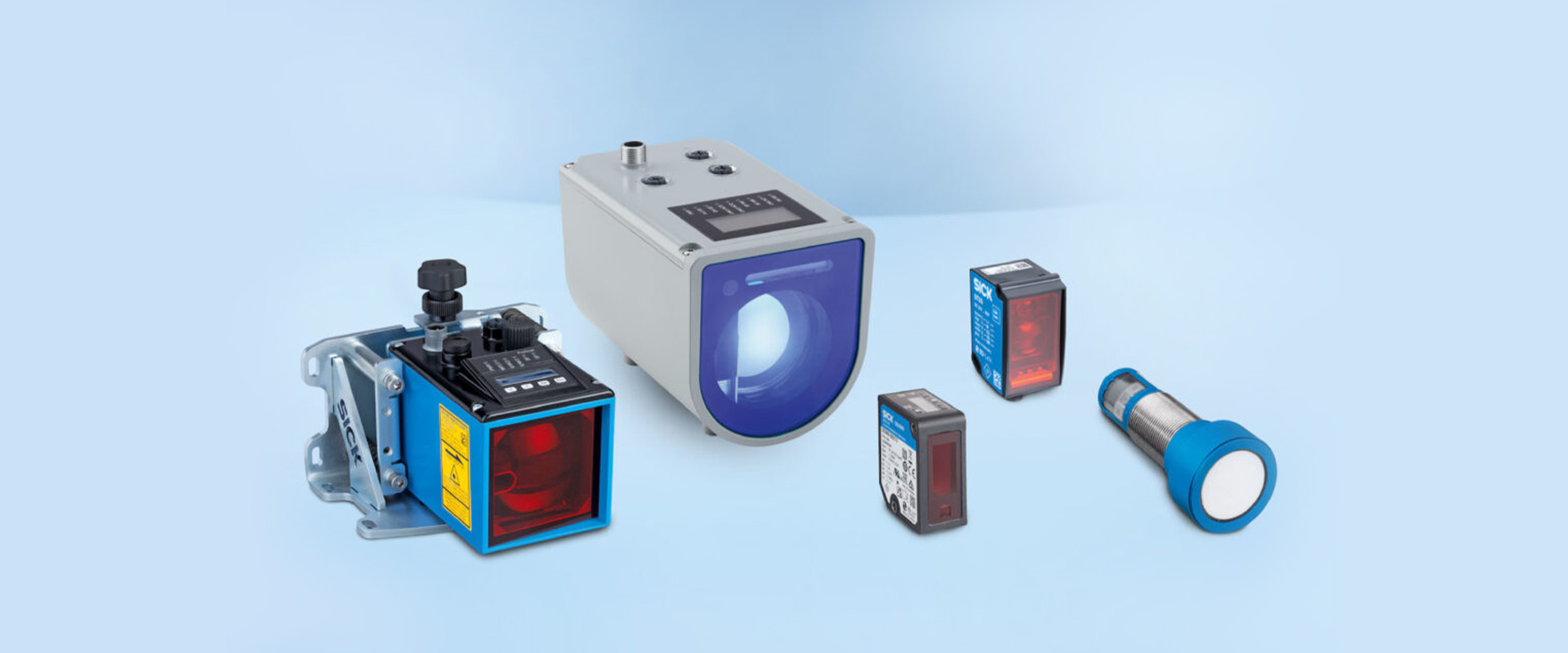
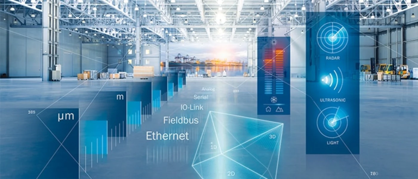
SICK’s official distance and laser measurement technologies cover a range of measurement distances, from the micron level to long distances. The product portfolio is categorized into several distinct categories, including displacement measurement sensors, medium- and long-range laser sensors, ultrasonic sensors, linear measurement solutions, and two- or three-dimensional sensing systems. These categories do not use the same physical principles to achieve their functions; rather, each type excels in addressing specific challenges related to the target surface, the surrounding environment, and the dynamics of the process being measured.
Classify the application correctly first
Short-range precision and quality inspection
For applications such as measuring differences in thickness, diameter, height, edge position, or surface profile, although the measurement range is relatively small, high accuracy is required. In these cases, resolution and repeatability are key considerations before considering the nominal range. Whether the part is black, shiny, semi-transparent, or textured can affect its optical reflection properties. The angle at which the sensor encounters the target, the size of the light spot, and vibration also influence the measurement results. Since different models within the same product family may have varying optical and laser specifications, it is essential to verify the specific technical parameters on the data sheet corresponding to the selected product code.
Medium-range positioning and material flow
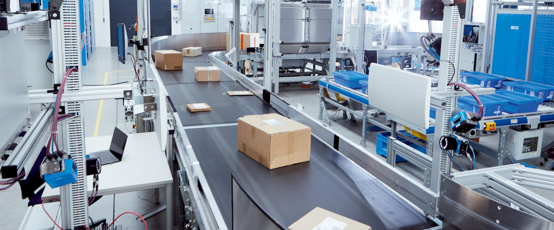
In applications such as measuring the height of stacks on conveyors, the diameter of coils, the position of carriers, or the distance between stacks, the sensor must be able to detect both variable surfaces and transmit a stable process value to the PLC. For simple tasks, a digital output may be sufficient; however, in cases requiring continuous monitoring, analog outputs, IO-Link, or serial communication are preferred. The measurement time must be shorter than the time the target remains within the sensor’s field of view, while the filtering settings should reduce noise without unnecessarily slowing down the control loop.
Long-range axis positioning
Reflector-based long-range measurement systems are commonly used in automated storage equipment, portal systems, cranes, and rail-based motion systems. In these applications, in addition to reliable position data, factors such as communication cycle time, mechanical alignment, reflector size, rail vibrations, and the influence of nearby optical devices must also be taken into account. It is far more crucial for maintenance teams to be able to detect contamination or signal degradation at an early stage than simply ensuring successful initial commissioning of the equipment. Transmitting the device’s diagnostic data to the control system facilitates a proactive maintenance approach.
Choosing between optical, ultrasonic and radar technologies
Optical time-of-flight measurementIt measures the time it takes for the emitted light to reach the target and return. Visible laser alignment can simplify the process; high-precision evaluation methods are designed to ensure reliable results in various environmental conditions. A small light spot can provide advantages when measuring narrow objects or delicate edges. However, in the case of highly reflective, mirror-like surfaces, overly dark objects, or materials that allow light to pass through, field tests are necessary.
Ultrasonic measurementIt utilizes the time it takes for an acoustic wave to reach the target and return. In most cases, the color or optical transparency of the object is not a determining factor; therefore, this technology represents a powerful alternative for transparent films, liquid surfaces, or products of various colors. However, factors such as the target’s geometry, sound absorption, air flow, temperature changes, and blind spots must be taken into account. If the sensors are installed in close proximity to each other, potential interference and synchronization options must be evaluated accordingly.
Radar-based measurementIt operates using radio waves, and can offer advantages in applications where there are specific external environmental conditions, dust, or adverse weather. The beam geometry of the radar, the cross-section of the target, and any metal reflections in the vicinity must be carefully considered for each particular application. The choice of technology should not be reduced to a simple comparison of “which one is the most robust”; instead, it must be determined based on the target, the background environment, the required accuracy, and the available installation space.
How does the target surface affect measurement?
The measurement range of a distance sensor is often specified in terms of a specific reflectivity, a reflector, or a standard target. The reflection detected from a white surface is not the same as that from matte black rubber; a shiny metal sheet may reflect the laser light in a different direction instead of sending it back to the sensor. Materials such as foil and glass can also produce different reflections depending on their front or back surfaces. For these reasons, testing with actual sample parts is an essential part of the selection process, especially in applications involving variably colored packaging or processed metals.
The angle between the target and the sensor is also important. A box moving on a conveyor may not present its flat surface at the same angle in each cycle. In the case of cylindrical coils, the measurement point may move as the diameter changes. The machine body behind small parts may create unwanted secondary targets. Functions such as learning limits, background suppression, averaging, and validity checks can only be properly configured after analyzing this geometry.
Technical specifications to assess measurement quality
- Measurement range: It must be able to cover the target’s closest and farthest actual positions, taking into account tolerances and maintenance margins.
- Resolution: The smallest value that the device can measure represents the minimum step size; it does not in itself imply absolute accuracy.
- Repeatability: Describes how closely repeated measurements agree under the same conditions and with the same target.
- Linearity or accuracy: It helps to identify any deviations between the measured value and the actual value.
- Response time and output delay: It determines the delay with which the control system receives the current distance information regarding fast-moving targets.
- Immunity to ambient light: Important where ceiling lights, sunlight, or neighboring sensor light are present.
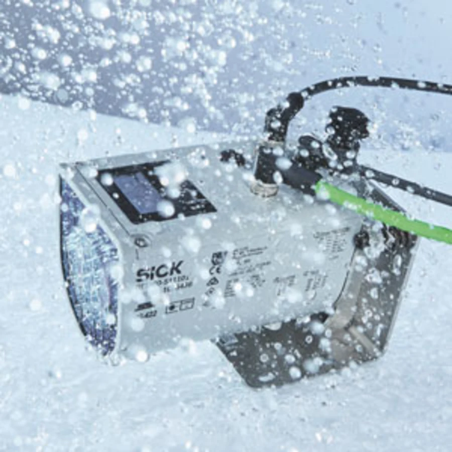
- Protection class and temperature: Interpret these ratings together with installation requirements covering the sensor, mated connector, and cable.
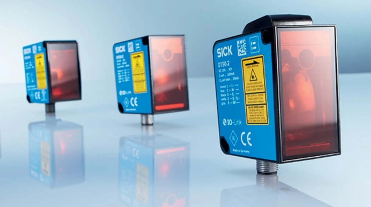
These values vary across different device families, and even within different models of the same family. For example, the Dx50 family includes various options regarding range, as well as digital, analog, or serial interfaces, and different laser classes. Therefore, the promotional information provided at the family level should not be considered as a guaranteed feature of a specific model or order code.
Communication and automation architecture
For a simple threshold control, a PNP or NPN switch output may be sufficient. For continuous distance monitoring, an analog signal of 4–20 mA or 0–10 V is a common solution; however, factors such as cable length, grounding, and scaling errors must be taken into account. IO-Link facilitates the transmission of diagnostic data and parameter information from a standard point, in addition to the measurement values itself. On high-speed position axes, industrial interfaces such as SSI, RS-422, PROFINET, or any other supported by the selected product can be directly integrated into the control architecture.
The decision regarding which interface to use should not be based solely on the availability of empty ports in the PLC. Factors such as the required cycle time, the need for time stamping, the cable routing, the device replacement scenario, the necessity of central parameter backup, and the network load must all be taken into consideration. If the distance measurement value is to be used within a safety function, it cannot be assumed that the standard measurement sensor alone constitutes a sufficient safety component; a thorough risk assessment and the implementation of an appropriate safety architecture are also essential.
Installation and commissioning checklist
- Measure the minimum and maximum distances based on the actual range of motion, and then add in the mechanical tolerance.
- Identify the toughest target to test: the darkest, brightest, smallest, or most angled sample.
- Check the sensor beam in three dimensions alongside protective windows, machine guards, and moving cable routes.
- Test the effects of neighboring optical sensors, welding arcs, sunlight, and high-frequency lighting on site.
- Record the output range, invalid measurement behaviors, filters, and thresholds in the same document as the PLC program.
- Do not confine diagnoses such as pollution alerts and signal quality assessments solely to the display screen; integrate them into the maintenance alarm system or the monitoring layer instead.
- Describe how to restore the parameters after device replacement, how to re-align the installation, and how to conduct the acceptance tests.
A practical selection approach by application
Coil diameter and sag: The change in target color, vibration, and the speed of updates are taken into consideration. The analog or IO-Link measurement value is then scaled according to the control algorithm.
Carton height on a conveyor: Stability across different surfaces, print patterns, and gaps; the field of view and conveyor speed are carefully calibrated. When multiple measurement points are required, the boundary between a single-point sensor and a profile sensor is clearly defined.
Warehouse stacker crane positioning: The reflector size, maximum range, lateral oscillation, speed, network cycle time, and stop accuracy are all taken into account in the calculation. If there are multiple optical devices in the same corridor, their mutual interactions are also examined.
Tank or container level: The pressure, temperature of the environment, as well as the presence of foam, steam, dust, and the movement of the target surface determine the principle of measurement. If the application requires connection to a process or operates in a explosive environment, a general-purpose distance sensor alone will not suffice.
Detection of outdoor vehicles or infrastructure: Factors such as rain, fog, sunlight, the color of the target, and long-term optical contamination are taken into account; if necessary, radar or LiDAR solutions are also included in the comparison.
What project deliverables does Oskon prepare?
The Oskon approach does not begin with the product code. Instead, the target object and background samples are identified, along with the motion profile, measurement tolerances, environmental conditions, and the existing control infrastructure. Subsequently, the appropriate SICK technology class is selected. The sensor, bracket, reflector, cable, and connecting accessories are then considered as a single assembly. The PLC configuration, error handling mechanisms, diagnostic alerts, and operator interface are all integrated under the same functional framework.
During the FAT phase, various test scenarios are conducted, including testing at maximum range, with the worst-case target, in cases of sensor contamination, and when the cable is disconnected, to verify the validity of the measurement results. During the SAT phase, reference measurements are taken under actual lighting conditions and in the presence of machine vibrations. The delivery documentation includes information on the device type, parameter settings, threshold values, installation dimensions, cleaning methods, and acceptance criteria. As a result, the sensor not only becomes a functional component but also a measurement point that can be easily managed by the maintenance team.
Frequently asked questions
Is the sensor with the longest range the safest choice?
No. An excessively large range may not offer any advantages in terms of light spot formation, resolution, cost, background interference, or mounting geometry. The most suitable operating range that ensures the required performance for the specific application should be selected.
Are black surfaces always impossible to measure?
Many optical sensors are capable of measuring dark targets; however, their effective range and repeatability may differ from the values measured on a white reference target. The final determination should be based on the specifications provided on the data sheet, as well as actual sample tests.
Are ultrasonic sensors more suitable for transparent objects?
Its reduced susceptibility to factors such as color and transparency is a significant advantage. However, the automatic selection of a particular type should not be made without considering the target’s sound reflection characteristics, its blind spots, as well as air flow and temperature conditions.
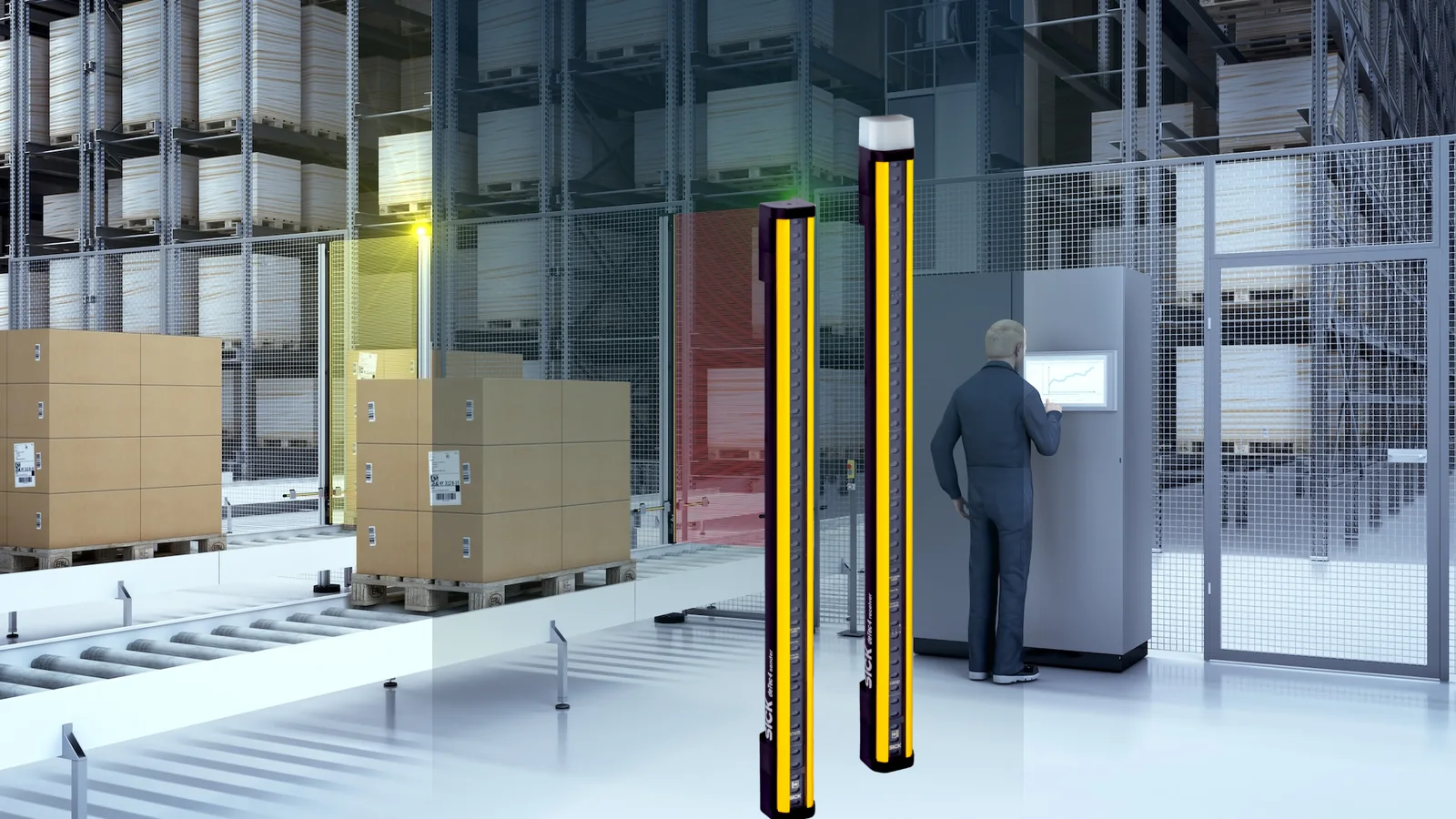
Can a distance sensor be used for machine safety?
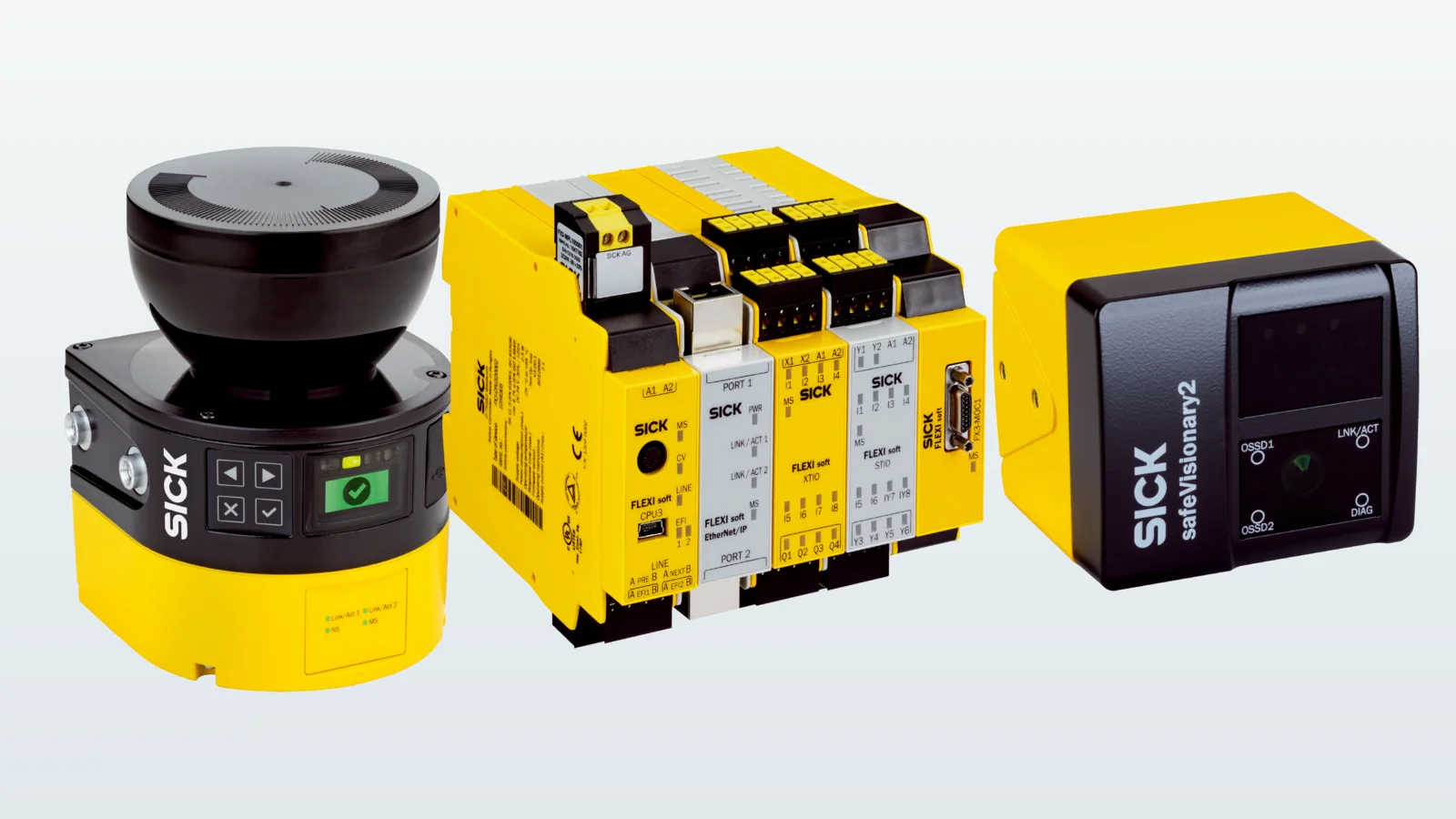
General-purpose measurement sensors are not automatically considered safety components. If human protection is a requirement, certified safety products that meet relevant risk assessment criteria, as well as safe control architectures, must be selected.