Plan robot access, geometric datums, joining sequences and part traceability together in bodyside and underbody production. The longest station cycle determines line capacity.
The different roles of underbody and bodyside production
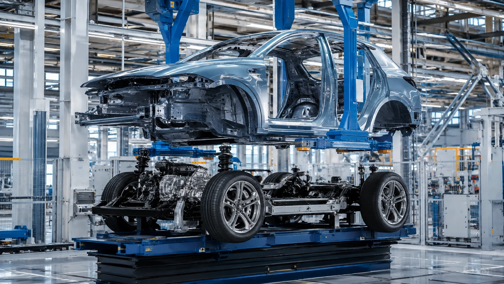
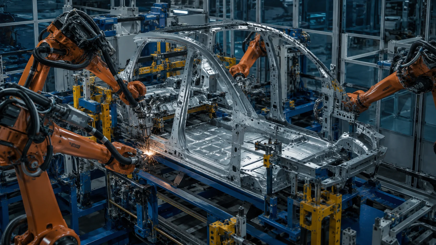
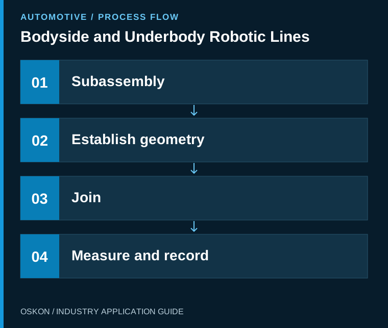
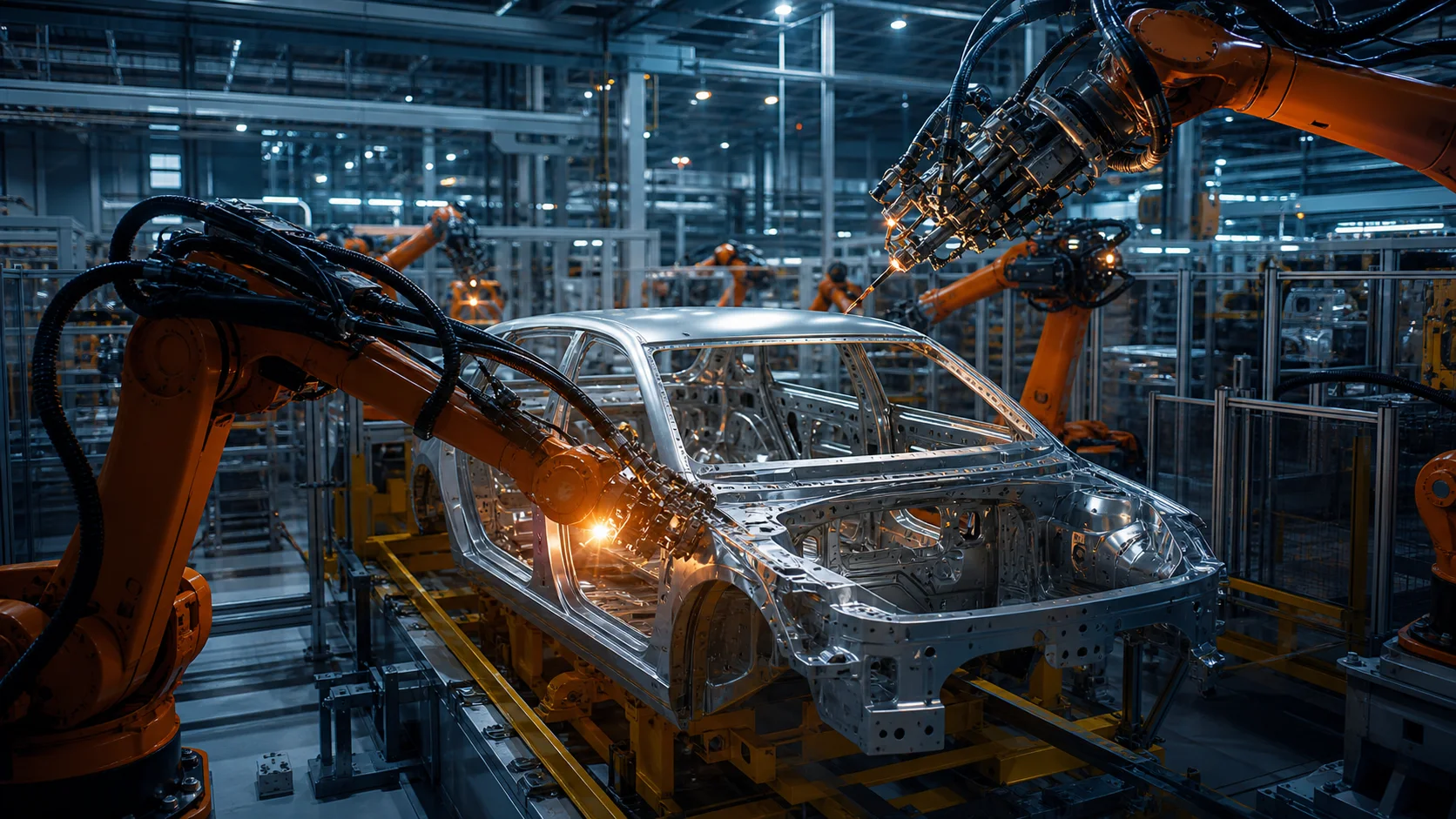
Underbody production covers the subassemblies forming the vehicle floor structure, while bodyside production covers the side body components. These parts provide the geometric foundation for subsequent body joining stations. A line cannot be assessed by robot count alone. The part family, joining methods, fixture changeover strategy and measurement plan are all inputs to the same design.
Geometry stations and completion stations
The relationship between the locators at the geometry-setting station and the datums used by subsequent stations must be clear. Review the joining sequence, the stage at which the fixture releases the part and how the part is supported during transfer. Distributing the same number of weld spots to every station does not create a balanced line: robot approach, welding gun access, part transfer and maintenance allowances also contribute to the cycle.
Coordination between robots
Define access permissions for shared work zones. A robot's request to enter a zone must be checked against the actual state of the other equipment. Workpiece identification helps select the appropriate robot program and fixture configuration. If communication is lost, an old permission must not remain valid. Design process coordination signals and the safety functions protecting personnel as separate responsibilities.
Model mix and capacity calculations
If different body variants will run in one shift, assess consecutive demanding variants as well as the average cycle. Include transfer times, welding equipment maintenance, electrode tip changes and fixture changes in capacity calculations. Update simulation inputs with actual motion and process times. Before investing in another robot, establish whether the bottleneck comes from mechanical transfer, processing time or waiting for permissives.
Measurement and traceability
Record joining results, the program version used and critical equipment states against the body identity. Linking measurement data to a specific station or fixture makes it easier to investigate the source of a deviation. Consider intermediate inspection points that prevent defective subassemblies from advancing, rather than assessing every dimension only at the end of the line. Customer requirements determine data retention periods and the method of transfer to the quality system.
Bring acceptance testing into the production flow
Test correct product routing, recovery of partly processed bodies and the rework route. Define the holding rule for an unreadable part identity. Compare result matching between the robot, welding controller and line PLC using sample bodies. Successful acceptance requires sustainable production across different variants and verified geometry, rather than a single fast cycle.
Key information to monitor in the automation system
| Control point | Monitored information |
|---|---|
| Body ID | Variant and program matching |
| Zone access permission | Robot and transfer coordination |
| Joining result | Record to be transferred to the quality system |
Three questions to ask at the start of the project
- Which station is the bottleneck for each variant?
- Where are the intermediate inspection and rework routes?
- Is the body's processing history retained after an interruption?
Explore related applications
Explore related processes in Semi-Automatic Fixtures and Door Robotic Lines. Browse all Automotive articles or visit Automotive solutions.