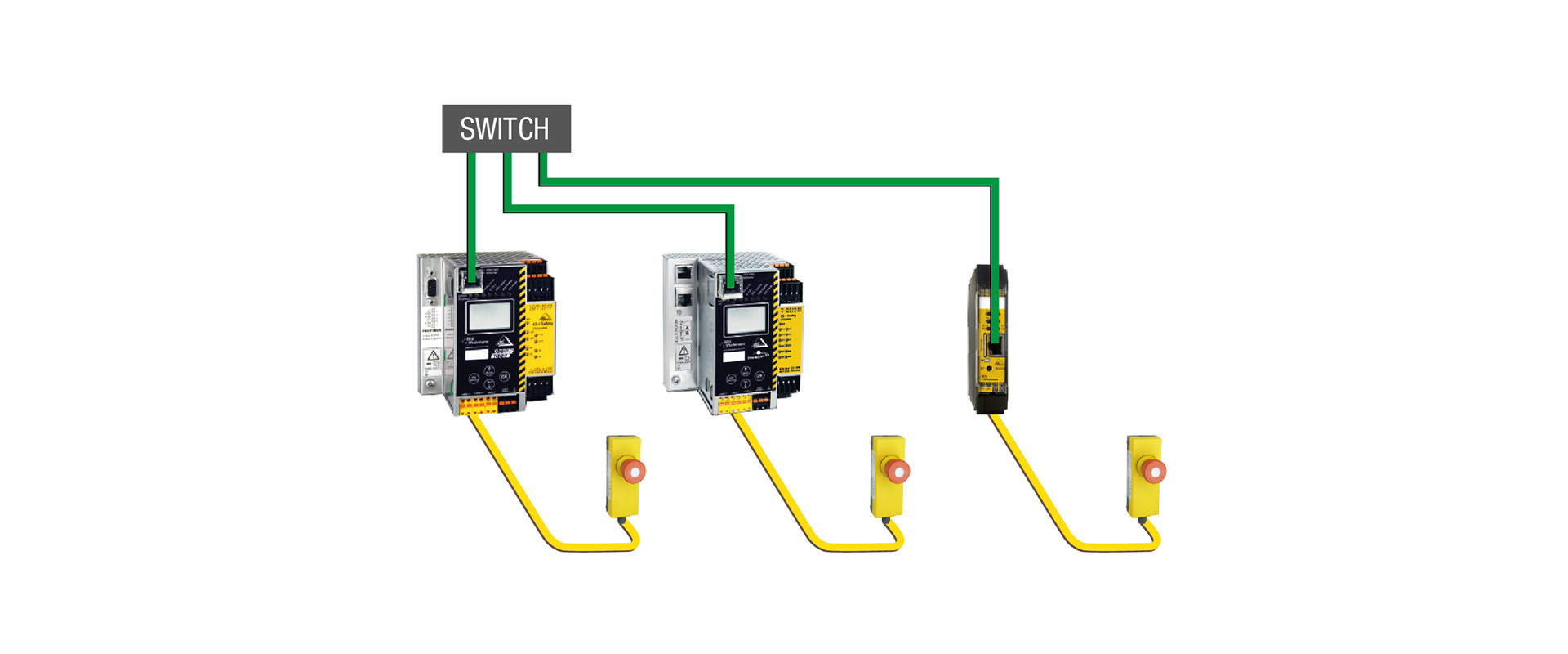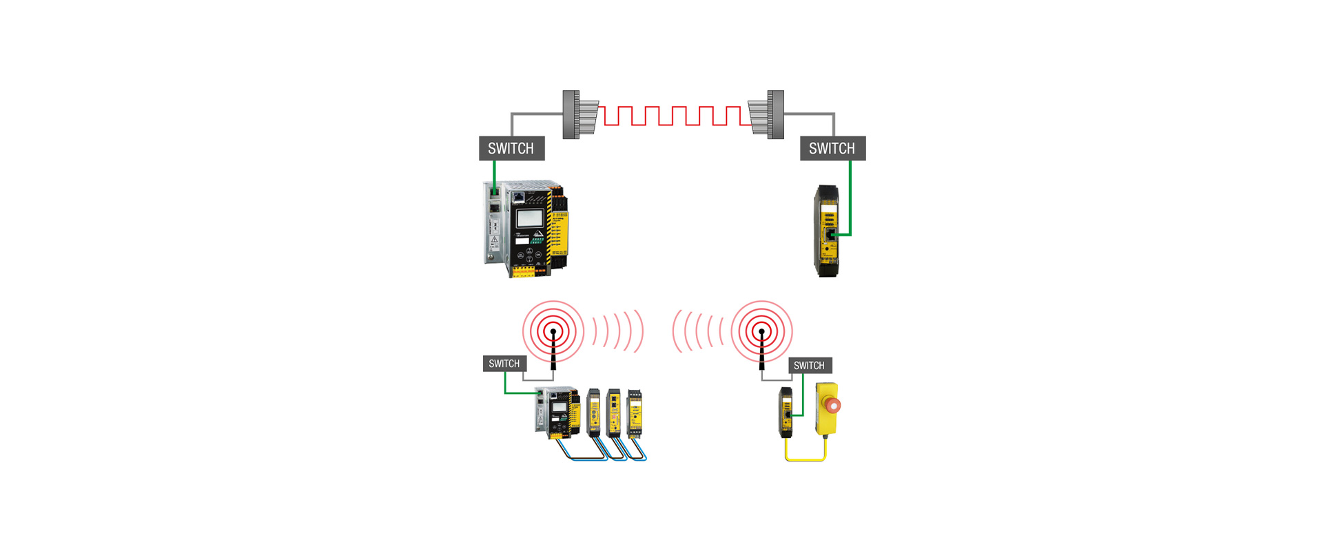
In the field of machine safety, the design of distributed I/O systems is not merely about using fewer cables to connect emergency stop buttons or protective door switches to a remote control panel. The type of sensors, the channel configuration, the diagnostic capabilities, the response time of safety functions, the field conditions, and the location where the safety outputs are to be generated must all be taken into consideration within a single architectural framework. Bihl+Wiedemann’s ASi Safety and ASi-5 Safety products offer various IP20 and IP67 options, enabling the collection of safety-related and standard signals in the field, their transmission to a safety monitor via AS-Interface, and their integration into the higher-level control system for diagnostic purposes. This guide explains this product family in a catalog-like format, linking each performance specification to the relevant product data sheet and the risk assessment considerations for specific applications.
The actual role of distributed safety I/O
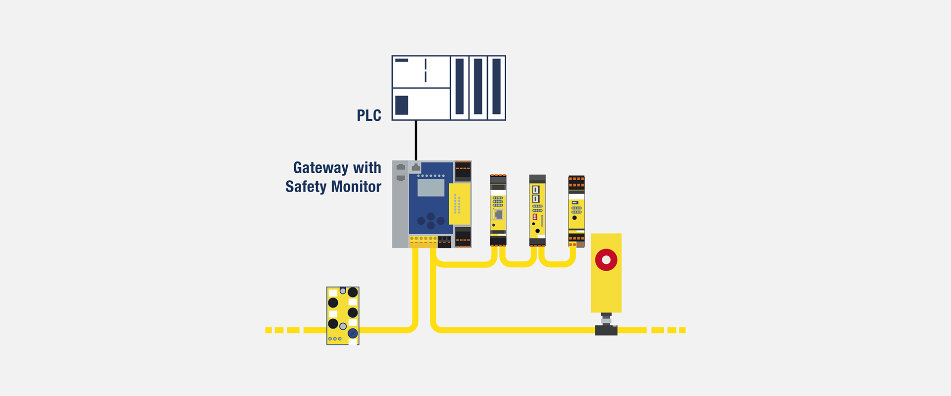
A safety input module is not merely a standard input card that merely “reads” the electrical status from safety devices in the field. In a two-channel emergency stop circuit, it helps to assess inconsistencies, the expected switching behavior of OSSD outputs, or the restart conditions of protective devices within the architectural framework required by the safety function. At ASi Safety, the safety signal can be transmitted along the same yellow-profile cable along with standard data. The safety monitor then evaluates these safety code sequences and controls the designated release circuit. This approach enables the reduction of multi-conductor parallel wiring between the physical location of the sensor and the main control panel.
The term “distributed” does not mean that safety functions are arbitrarily distributed across the field. It is clearly documented which input corresponds to which safety function, as well as the communication pathways from the input module to the monitor, the safe outputs, the safe inputs of contactors or drives, and any feedback mechanisms. The presence of standard outputs in a network does not imply that they are safe outputs. Similarly, the fact that a module is specified to meet PL e or SIL 3 requirements does not mean that the entire machine automatically complies with these levels; additional considerations include the device’s fault tolerance, diagnostic capabilities, measures to prevent common faults, operational life expectancy, and verification results.
| Selection question | Initial approach | Detail to verify |
|---|---|---|
| Does this device have potential-free contacts? | The safety input variant defined for potential-free contacts | Single/dual channels, test pulses, cross-circuit detection, and cable layout. |
| Does this device have an OSSD output? | Safety input variant that accepts OSSD signals | Power supply, compatibility with OSSD test signals, restart functionality, and error response mechanisms. |
| Is the module installed in the control panel or in the field? | IP20 in the cabinet; a suitable IP67 field module on the machine | Temperature, IP ratings, vibration, M12 thread size, sub-modules, and protective covers. |
| Are there also standard signals available? | The ASi-5 Safety module, which features both safe and standard channels in the same module. | The safe/standard function of this channel, AUX power supply, and address/data mapping. |
| Is a local safety output required? | Appropriate I/O devices with safety outputs or safety monitoring solutions. | Output type, load, EDM, response time, and transition to safe state. |
An in-panel solution: the BWU4187 example
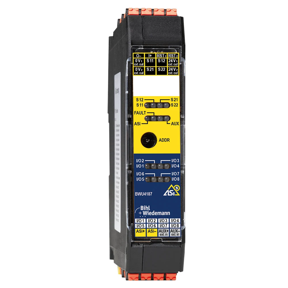
On the official product page, the BWU4187 is listed as an IP20 ASi-5 safety input module with a width of 22.5 mm. This specific variant can be configured to provide four single-channel or two dual-channel safe inputs for OSSD signals, in addition to up to eight standard digital inputs and eight standard digital outputs, depending on the configuration. The product page indicates that when the safe inputs are used in single-channel mode, the device is suitable for applications up to SIL 1, Category 2, PL c; when used in dual-channel mode, its suitability extends up to SIL 3, Category 4, PL e. These two statements serve as clear examples illustrating that different combinations of connections to the same terminal are not equivalent.
Push-in terminals can simplify repetitive cabinet wiring. Clearly show terminal numbers, the channels assigned to each OSSD pair, AUX sensor and actuator supplies, and the fact that standard outputs are not safety outputs. Carrying many safety-related and standard signals under one ASi-5 address can save address space and cabinet room, but commissioning must map logical channel names to actual machine device tags.
When does this variant make sense?
If the illuminated buttons on the operator panel, the standard selectors, and the safe outputs of an OSSD device are all concentrated in the same local panel, this multi-functional design can reduce the number of required components. However, the fact that a single module handles all these signals does not necessarily mean it represents the optimal layout for every application. If the cable routing is extensive, the field devices are located in different areas, or it is necessary to avoid replacing the entire panel in the event of a fault, a more distributed layout may be more appropriate. Additionally, since this configuration does not include local safe outputs, it is necessary to specifically determine which monitor or field module will generate the safe signals required to stop dangerous movements.
IP67 field modules: distinguish contacts from OSSD signals
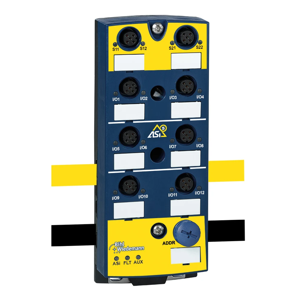
The BWU4209 and BWU4210 are IP67 ASi-5 safety field modules that look very similar to each other; therefore, the selection should not be based solely on their appearance. According to the official product specifications, the BWU4209 is designed for use with potential-free contacts, while the BWU4210 is designed for OSSD signals. Both models offer eight five-pin M12 connectors, four single-channel or two dual-channel safe inputs, up to twelve standard digital inputs/outputs depending on the configuration, and one ASi-5 address. Power for sensors and actuators is supplied via the AUX interface; it is also important to consider the appropriate sub-modules when making a selection.
A door switch with potential-free contacts does not generate electricity; it operates in conjunction with the module’s testing and evaluation mechanisms. An OSSD device, on the other hand, produces self-monitoring semiconductor safety outputs and is capable of applying short-test pulses. Connecting the device to the incorrect input type may result in ambiguous diagnostic readings, invalid test pulses, or the safety function not performing as intended. The product code, terminal pins, the OSSD specifications of the sensor manufacturer, and the current user manual for the module should all be compared within the same design validation process.
Design benefits of field installation
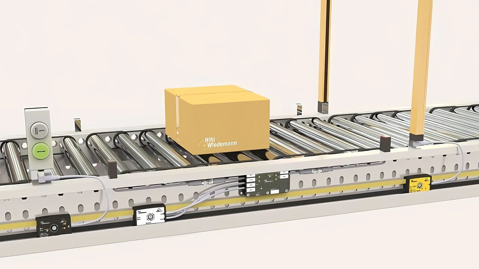
Connecting nearby conveyor guard switches, emergency stops and standard photoelectric sensors to the same module lets sensor cables terminate at the nearest node. ASi profile cable carries data and power along the line, reducing conductors returning to the main cabinet. M12 connections simplify preassembly and replacement. Correct connector coding, caps on unused ports, protection from cable strain and bending, and manufacturer-compliant ASi/AUX piercing contacts remain essential.
The IP67 rating alone does not constitute a certification of compatibility with any washing process, chemical substances, or outdoor conditions. This rating applies only to properly installed components, using suitable seals, and with all ports securely closed. Additionally, factors such as ambient temperature, mechanical shocks, vibration, as well as the presence of oils and cleaning agents must also be taken into consideration. If the module base is not included in the delivery scope, it must be explicitly specified on the product documentation; otherwise, even if the electronic module arrives at the site, the mechanical and electrical installation cannot be completed.
Performance level cannot be inferred from a product label
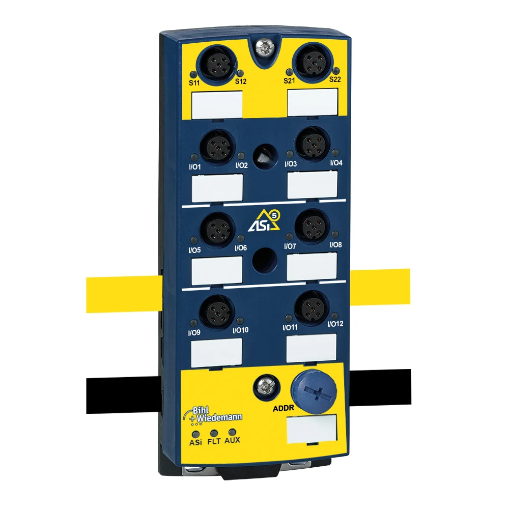
On the product pages of these three examples, the phrase “applicable in applications up to Category 4/PL e/SIL 3” is mentioned. This indicates that the device possesses features that enable it to meet these higher safety requirements when configured using its two-channel architecture. The actual PL or SIL level achieved by the machine is determined by considering all its subsystems, including the reliability of the input devices, the wiring, the modules, the communication system, the safety logic, the safe outputs, the contactors or drives, as well as the test intervals and diagnostic functions. It is important not to overlook the lower safety limits specified for the single-channel version of these devices.
The starting point is risk assessment: By evaluating the severity of the hazard, the frequency of exposure, and the likelihood of avoidance, the required performance objectives are determined. Next, the safety function is described in clear terms; for example, “When the door opens, the energy generated by the motors in that area must be safely interrupted within a specified time frame, and automatic restart must not occur once the door closes.” Calculations and verifications are then conducted based on this safety function. Details such as the series connection of multiple doors, the potential for error masking, or a shared AUX power supply can all affect the overall outcome.
Using ASi-5 Safety together with standard I/O
One of the notable features of ASi-5 Safety is its ability to transmit multiple safe and standard signals under the same address. This design allows components such as dual-channel emergency stop buttons and illuminated buttons in an operator’s panel, or OSSD devices and standard status sensors within a protection zone, to be integrated into the same field device. While this approach offers cost and cable-saving advantages, it is essential that the functionality of each component be clearly indicated in the software documentation. The standard channel must not be used to replace the necessary safe inputs or outputs of a safety function.
Document the AUX supply separately. A shared auxiliary source for sensors and actuators means one interruption may affect multiple channels. Whether using passive safe disconnection, local safety outputs or central contactors, test where energy is interrupted and how the system behaves when it returns. Do not assume restart, reset and External Device Monitoring (EDM) logic already exist in the PLC program; explicitly assign responsibility within the safety configuration.
Response time and zoned stopping
When selecting a distributed network, it is not sufficient to consider only the maximum number of nodes or the total cable length. Factors such as the sensor response time, the processing time of input modules, secure communication capabilities, safety monitoring functions, and the response times of output devices and actuators must also be taken into account. If the distance between the protective device and the potential hazard is determined based on these combined factors, the worst-case values should be used. The fact that the network appears to operate quickly under normal conditions does not replace the documented worst-case response time of the safety function.
In long machines, it may be unnecessary for each emergency stop to shut down the entire line, from a production perspective; however, a partial shutdown is implemented if a risk assessment indicates that adjacent areas remain safe. The specific areas affected by the safety signal, the presence of product or mechanical energy at the transition points, coordination for resuming operations, and access requirements for maintenance are all specified in the functional documentation. Distributed I/O systems provide a flexible infrastructure for such zoning, but they do not determine the boundaries of the safe areas on their own.
Commissioning and validation sequence
- Product identity: The electronic module, sub-modules, socket layout, complete product number, and the version of the data sheet are compared with the material list.
- Electrical matching: The type of OSSD or potential-free contact, as well as the single/dual-channel configuration, AUX voltage level, pin arrangement, and the rules regarding the use of shields/earthing, must be confirmed.
- ASi configuration: The address, profile cable polarity, piercing contacts, topology, power budget, and permitted line conditions are all checked.
- Logical testing: each sensors are activated one by one; it is confirmed that they trigger the correct safety function and do not affect unrelated areas in any unexpected manner.
- Fault injection: Issues such as channel interruption, inconsistency between channels, OSSD errors, AUX signal loss, ASi communication interruptions, and output feedback errors are tested in accordance with established safety procedures.
- Restart: It is confirmed that no unexpected movements occur after the energy return, the door closes, and the fault is resolved.
- Registration: Link measured response times, test results, software version, checksum and approver to change management.
Make diagnostics useful for maintenance
One of the key benefits of distributed I/O is its detailed fault diagnosis, which helps to locate the issue more closely to the actual field location. For this to be effective, the display on the screen must not merely indicate “Safety fault” – the message should also include information such as the machine area, device identifier, affected channel, expected status, and potential corrective actions. For example, a message like “Door switch in Area 4: Two channels are not synchronized” can significantly reduce maintenance time compared to a generic network error notification. The fact that the safety status is displayed on the HMI does not mean that safety decisions are made solely through the HMI itself; rather, the HMI serves as a diagnostic tool.
During device replacement, the transfer of addresses and parameters must be controlled carefully. Mixing BWU4209 and BWU4210, which have the same physical format, can result in mismatched contact and OSSD functions. Spare parts should be stored along with the full product number, revision information, and any required sub-modules. Even if automatic configuration transfer occurs after replacement, functional testing must still be performed. Aligning diagnostic logs with timestamps, field observations, and PLC event data facilitates the analysis of the root causes of intermittent failures.
Quotation and project start-up checklist
- The hazard associated with each safety function, the required PLr/SIL target, the safe state, and the maximum response time.
- Number of potential-free contacts, OSSDs, standard inputs, standard outputs, EDMs, and safe outputs
- Single/dual-channel architecture, simultaneity, test-pulse compatibility and restart behavior
- IP20/IP67 layouts, M12 cables, sub-modules, covers, as well as environmental and cleaning conditions.
- ASi-5 address scheme, topology, profile cable, AUX power budget, and voltage drop.
- Safe output terminal, load type, contactor or drive interface, and feedback mechanism.
- Safety monitor, safe connection, standard fieldbus, and the scope of responsibility for diagnostic data.
- Calculation file, software version, backup, validation protocol and periodic test plan
A properly selected Bihl+Wiedemann safety I/O architecture reduces the amount of wiring required while making the responsibilities between the field devices and the control panel clearer. A well-designed project incorporates the exact variant of components, the actual type of sensors, the method of energy disconnection, and the verified safety functions in the same documentation, rather than merely replicating the maximum value of the product family.