The presence of a 24 V DC voltage in an automation panel does not necessarily guarantee reliable power supply under all operating conditions. Power line fluctuations, switching surges, lightning impacts, short-term interruptions, loads with high inrush currents, and short circuits in an output circuit are all different types of risks associated with the same power distribution system. For this reason, Phoenix Contact’s range of overvoltage protection devices and power supplies should not be considered as individual components, but rather as part of a coordinated system that includes protection, conversion, distribution, and monitoring functions, from the power input to the sensitive control devices.
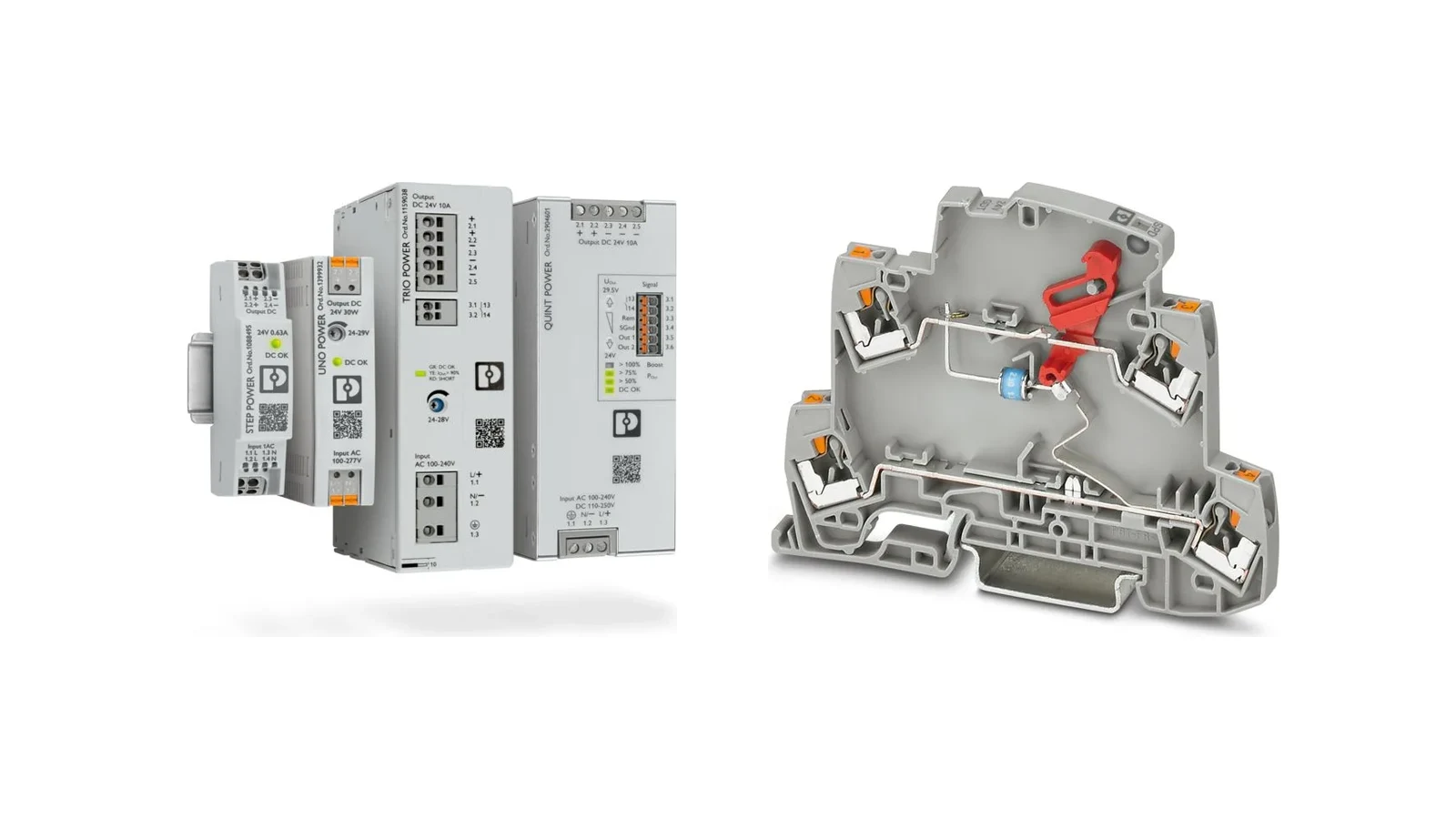
This catalog guide is designed to help you match Phoenix Contact product families with the right applications. While the QUINT POWER, TRIO POWER, UNO POWER, and STEP POWER families address various functional and space requirements, the overvoltage protection families such as FLASHTRAB, VALVETRAB, PLUGTRAB, and TERMITRAB COMPLETE respond to different threats in power, signal, and communication systems. The name of a product family alone should not be the sole basis for making a purchase decision. The system configuration, number of phases, nominal input and output values, load profile, short-circuit behavior, installation location, ambient temperature, required notifications, and applicable standards must all be verified in conjunction with the current technical data sheet for the selected product code.
Assess power supplies beyond their wattage alone
The starting point for calculating power requirements is the continuous current load; however, the final decision is not based solely on this figure. Devices such as PLCs, remote I/O modules, sensors, valve islands, relays, HMIs, industrial switches, and other 24 V DC consumers must be listed separately. In addition to the normal operating current, factors such as inrush current, simultaneously connected loads, capacitive loads, temporary demands from motor or contactor coils, and potential future expansion needs must also be taken into account. Without considering both the output characteristics of the power supply and the switching behavior of the protective components, even a high-capacity power supply may fail to provide selective disconnection of the faulty branch.
On Phoenix Contact’s latest product page, power supplies are categorized into DIN rail-mounted, wall-mounted, IP67-rated field-mounted, and 19-inch rack-mounted types. For traditional applications in control panels, DIN rail-mounted products are the preferred choice, while IP67-rated models are suitable for decentralized power distribution systems. The panel-mounted TRIO POWER series offers higher power outputs and meets various mounting requirements; rack-mounted solutions, on the other hand, are designed for use in dedicated mechanical enclosures. These categories are not direct alternatives to each other—the device’s ventilation requirements, mounting orientation, conductor connections, and heat dissipation factors must all be carefully planned in accordance with the manufacturer’s specifications.
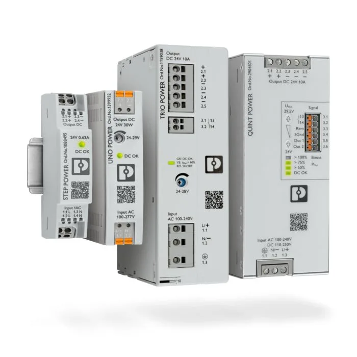
How do QUINT, TRIO, UNO and STEP POWER differ?
QUINT POWER products from Phoenix Contact are designed for applications that require high levels of functionality. The latest product page details features such as static and dynamic boost, SFB Technology, adjustable signal thresholds, and – in certain configurations – adjustable output characteristics. The purpose of SFB Technology is to enable the selective tripping of standard miniature circuit breakers through appropriate circuit design, thereby ensuring the continued operation of parallel circuits. It should be noted that this does not mean that each circuit breaker will automatically trip selectively for any given cable length; factors such as cable impedance, short-circuit current levels, protection characteristics, and the specific power supply variant must also be taken into account.
TRIO POWER is offered as a robust family of products that focus on standard functions in machine and system manufacturing. The product page lists features such as compact design, push-in connections, dynamic boost, multi-colored LEDs for diagnostic purposes, and collective signaling relay contacts; some options also include IO-Link functionality and integrated multi-channel device protection. The phrase “some options” is important here—since the communication or protection features available in one TRIO POWER model may not be available in all members of the family. The product description must clearly state the device protection channels, communication capabilities, and connection methods, along with the input voltage range and output current specifications.
UNO POWER is designed for compact control cabinets where basic functionality and high power density are the top priorities. STEP POWER, on the other hand, offers solutions for distribution panels, building automation systems, and other applications with limited or narrow installation spaces. A variant of these product lines with more basic monitoring functions can be a suitable and cost-effective choice for applications with simple load requirements. However, in systems where installation costs are high, remote diagnostics are necessary, or complex loads need to be controlled, relying solely on compactness can be risky. The selection process must clearly align with the availability objectives of each specific project.
Why is surge protection a separate layer?
The presence of varistors or transient surge protection circuits at the input of a power supply does not necessarily mean that the entire facility is adequately protected against lightning strikes and overvoltage. Phoenix Contact’s overvoltage protection page explains this protection approach in detail, covering areas such as power supplies, measurement and control signals, information technology systems, and transmitter-receiver lines. In facilities equipped with external lightning protection systems or where the power supply lines pose risks, the protection measures at the main distribution level, sub-distribution level, and at the end devices must be coordinated in accordance with relevant risk analysis and standards. The type of protection device chosen depends on its ability to handle lightning currents, its installation location, and the requirements for limiting residual voltages.
Type 1 and Type 1+2 solutions are typically installed in areas near the power grid entrance, where the impact of lightning currents must be taken into account. Type 2 solutions are used at the distribution level to protect against switching and residual surges. Type 3 solutions serve as an additional layer of protection in areas near sensitive end devices. This description provides a general framework for selection but does not provide direct product codes. The appropriate grid configuration (TN, TT, or IT), the number of phases, the neutral-PE relationship, the continuous operating voltage, the short-circuit resistance, the backup fuses, and the connection lengths must be confirmed using the manufacturer’s selection tables. It should not be assumed that a product selected for AC applications is also suitable for DC systems or photovoltaic systems.
Protecting the power line alone is insufficient
Even if a panel is powered by protected circuits, analog, digital, or communication cables extending outside the panel can still cross the protection boundary. In Phoenix Contact’s “effective protection circuit” approach, every conductive path that crosses the boundary of the area to be protected is taken into consideration. Therefore, signals such as 0/4-20 mA and HART signals from remote sensors, digital I/O lines, Ethernet connections, and antenna cables require protection that is appropriate to their specific signal types. The surge suppressors used on the power supply side cannot be directly applied to low-level measurement signals; it is essential to protect the signal voltage, nominal current, frequency or bandwidth, as well as the grounding configuration.
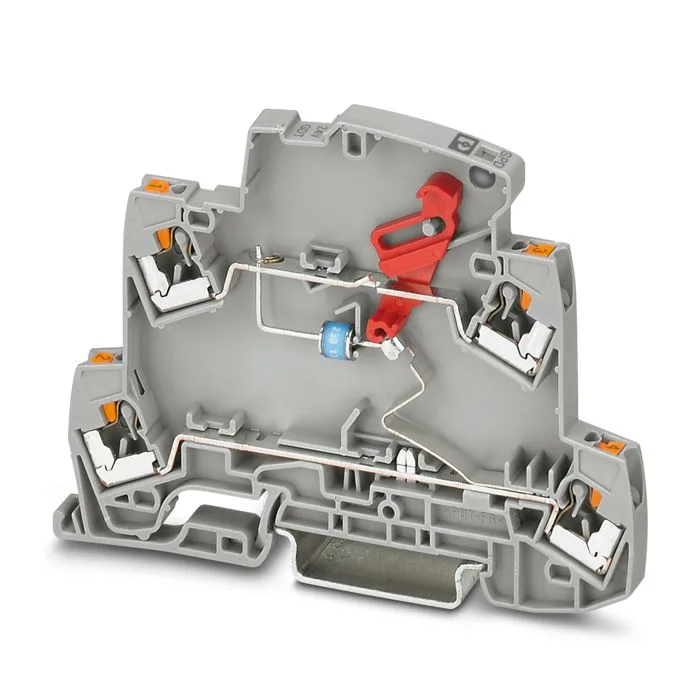
TERMITRAB complete is a slim surge-protection family for measurement and control technology. The official website offers a wide range of options, ranging from single-stage solutions to multi-stage plug-in versions equipped with separation blades, signal output, and alarm contacts. For the thinnest models, the module width of 3.5 mm is specified. The PLUGTRAB PT-IQ series features advanced multi-stage status monitoring; the CLIXTRAB series offers protection systems integrated with the terminal block design; the SURGETRAB series provides options for close installation near field devices. These functions depend on the specific product model—for example, for use in Ex zones, HART circuits, or SIL applications, only products that have the necessary certifications and technical specifications must be selected.
Design protection, power supply and branch selectivity together
In a robust 24 V DC architecture, the overvoltage protection devices on the grid side safeguard the power supply; the power supply itself converts the electrical energy; electronic or thermomagnetic circuit breakers disconnect the output circuits; when necessary, two power supply and redundancy modules together supply the load. During short interruptions, the UPS and an appropriate energy storage unit ensure continued controlled operation. Since each layer of the system responds to different types of faults, statements such as “Since the power supply is redundant, surge protection is not needed” or “Since there is a fuse, an UPS is unnecessary” are incorrect.
In a redundant power supply system, it is also essential to verify whether the two sources are truly independent of each other. If two devices are connected to the same input fuse, follow the same cable routing, and are subject to the same overvoltage events, merely connecting their outputs in parallel will not eliminate potential common faults. The redundancy mechanism is designed to prevent reverse currents and mutual interference between the power sources; factors such as load sharing, cable cross-sections, voltage drop, and monitoring contacts are all carefully monitored during the commissioning process. In the case of UPS systems, key considerations include the required backup duration, the technology used for batteries or capacitors, ambient temperatures, the impact of aging, and a comprehensive periodic testing plan.
| Design question | Phoenix Contact solution area | Data to verify in the project |
|---|---|---|
| What functional level does a 24 V DC load require? | QUINT, TRIO, UNO, or STEP POWER | Input, output, power backup, diagnostic functions, connection, and mounting. |
| What is the risk of surge damage at the network entrance? | FLASHTRAB, VALVETRAB, or PLUGTRAB product families | Network topology, SPD type, Uc/Up, discharge capacity, and backup protection. |
| How can sensitive field devices be protected? | Type 3 device protection | Distance, coordination, AC/DC voltage levels, and status notifications for remote devices |
| Does the field signal cross the protection boundary? | TERMITRAB complete, PLUGTRAB PT-IQ, CLIXTRAB, or SURGETRAB | Signal type, nominal values, earthing, frequency, and Ex/SIL classification if applicable. |
| Will a fault in one of the output branches cause the entire system to stop? | Device circuit breakers feature SFB-compatible design and power reserve capabilities. | Short-circuit current, cable impedance, trip curve, and selectivity calculation |
| Should operations continue in the event of a power supply interruption? | UPS, energy storage, and redundancy modules | Backup time, load profile, temperature, lifecycle, and common causes of failures |
Installation and earthing details
The performance of an overvoltage protection device depends not solely on the technical specifications indicated on its front panel. The connection wires must be kept short and of appropriate cross-section; the routing of the protective wires should avoid creating unnecessary loops, and the manufacturer’s wiring diagrams must be followed strictly. Running protected and unprotected cables alongside each other over long distances can allow interference to couple back into the protected circuit. The internal equipotential bonding within the control panel, the function of DIN rails, the proper connection of shielding wires, and the implementation of on-site grounding measures must all be considered within the overall framework of the system’s EMC and lightning protection strategies.
During the installation of a power supply, the mounting orientation and surrounding clearances can affect its cooling performance. The nominal current specified in the technical data sheet may vary depending on the input voltage, operating temperature, and installation conditions; high temperatures or different mounting orientations may require adjustments to the performance parameters. The allowable cross-section of the cable, as well as the length of the stripped section and the clamping torque, must be selected according to the specific connection method. The fact that push-in connections require no special tools does not mean that the preparation of the conductors is unimportant. During commissioning, it is essential to check the DC output settings, polarity, voltage under load, status indicators, and the device’s thermal conditions.
Information required for quotations and project planning
- Describe the system: Specify whether it is AC or DC, the nominal voltage, the number of phases, the frequency, the TN/TT/IT system, and the existing lightning protection measures.
- Generate the load list: Record continuous, starting, and peak current for each load, along with simultaneity and expansion allowances.
- Please enter the goal of continuity: Determine which loads should operate in the event of a single-line failure, the permitted duration of the interruption, and the required alarms.
- Establish SPD coordination: Plan the locations for main distribution, sub-distribution, and end devices; determine the cable lengths required; and assign them to Type 1/2/3 duty categories.
- Count all the conductive paths: In addition to providing energy, also include analog/digital signal connections, Ethernet, fieldbus, and antenna connections within the protection system.
- Describe the environment: Enter the panel internal temperature, altitude, vibration level, humidity, protection class, and any Ex requirements as selection criteria when choosing the product.
- Verify the calculations: Calculate the voltage drop, short-circuit current, fuse tripping time, selectivity, heat loss, and UPS runtime based on the actual cable layout.
- Check the documentation scope of application: Verify standard compliance, certifications, suitability, and cyber communication features based on the specific order code, rather than the product family designation.
In Oskon’s approach to projects, Phoenix Contact power supplies and overvoltage protection products are not considered as separate items, but rather as components of the energy continuity chain. To determine the right product, various factors such as the load table, the electrical system and grounding configuration, short-circuit calculations, protection zones, the thermal conditions of the control panel, and maintenance scenarios must be taken into account. The final selection should be based on the latest technical data sheets, installation instructions, compatibility of accessories, and applicable facility standards.