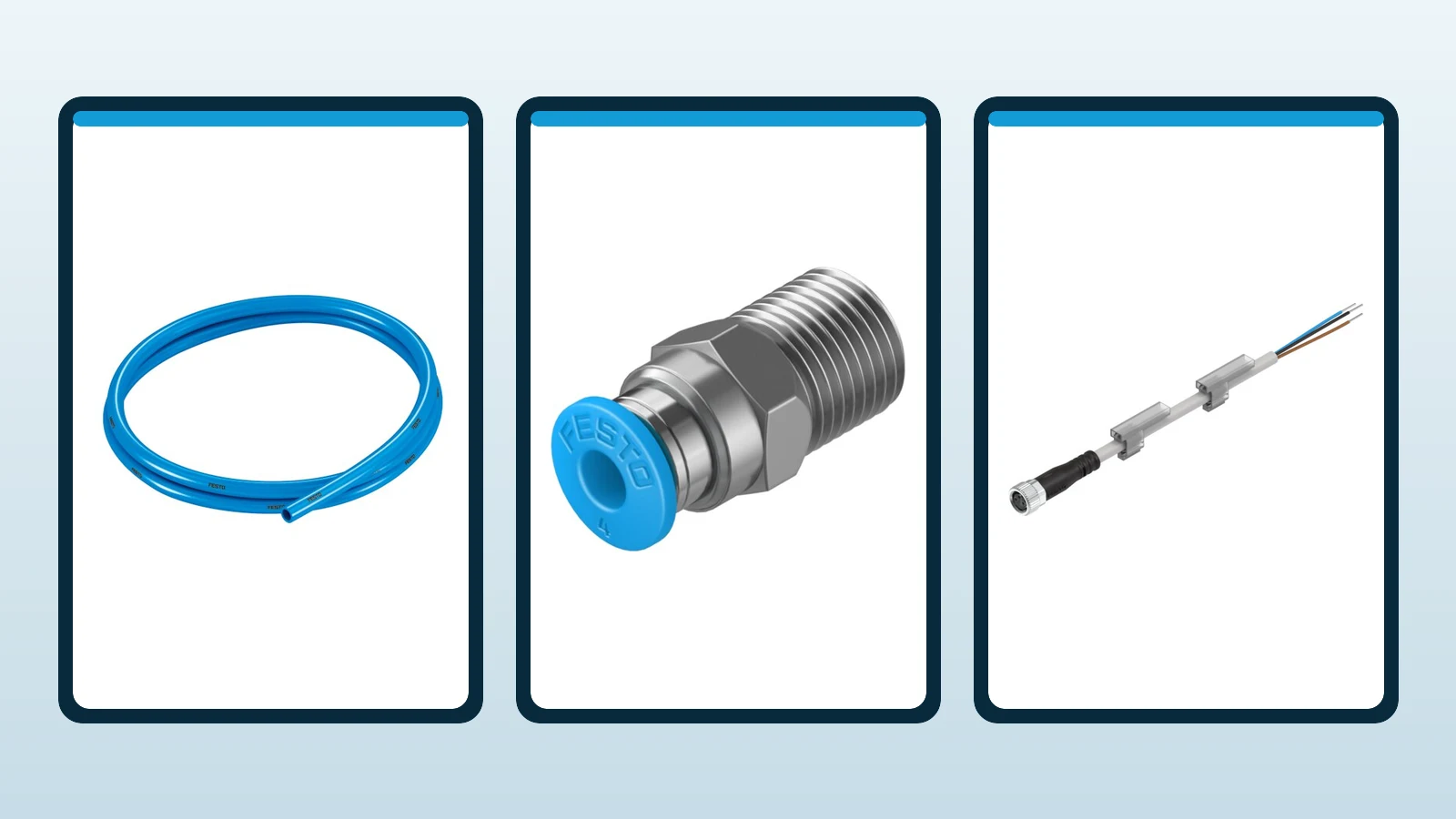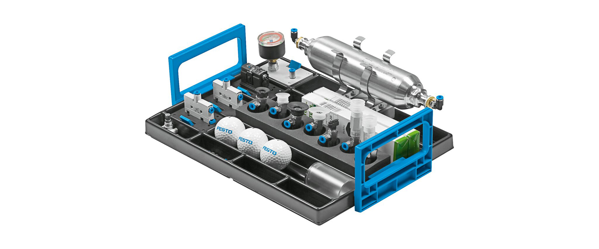
Process valve automation does not merely involve connecting an actuator to the valve. The properties of the fluid, the valve’s requirements for torque or thrust, its opening/closing or modulation functions, its normal operating speed, feedback systems, air quality considerations, communication requirements, safety aspects related to energy loss, and the classification of the area where the system is installed—all these factors must be taken into account within the same architectural framework. This catalog guide introduces Festo’s portfolio for process automation, covering quarter-turn and linear actuators, positioners, limit switch boxes, pilot valves, and connecting components. The name of a product family in itself does not indicate compliance with SIL or ATEX standards; the final selection must be confirmed by checking the relevant product code along with current documentation and certifications.
Start with the process task before the product
A process valve can be used to isolate a line, direct the flow of a product, fill a tank, reduce pressure, regulate temperature, or cut off the flow in an emergency. Two valves of the same nominal diameter require different automation architectures to perform these functions effectively. The first step in implementing such a system is to record relevant information—such as the fluid type, pressure, temperature, valve type and size, normal operating conditions, shutdown requirements, cycle frequency, and maintenance strategies—on the process data sheet.
Next, the control objectives are defined. The on-off function causes the valve to move between two stable positions, and in most cases, a simple open/closed signal is sufficient for this purpose. The modulation function, on the other hand, continuously changes the valve position to participate in control loops for regulating flow rate, pressure, level, or temperature. When using modulation, simply issuing a “50% position” command does not guarantee that the process will produce 50% of the specified flow rate; the valve’s characteristics, the pressure difference, the fluid type, and the piping system all play a role in determining the actual output. For these reasons, the selection of control valves, as well as the choice of pneumatic actuators and positioners, are interrelated but represent separate engineering considerations.
| Task | Initial architecture | Information that determines the decision |
|---|---|---|
| On/off operation of a ball or butterfly valve | Quarter-turn actuator + pilot valve + limit switch box | Valve torque curve, 90° movement, operating time, air pressure and safe position |
| Modulation of a ball or butterfly valve | Quarter-turn actuator + electro-pneumatic positioner | Control signal, dead band, air capacity, process dynamics, and feedback. |
| Globe valve, gate valve, knife gate valve or damper | Appropriate linear actuator + feedback system/positioner | Stroke, pushing and pulling forces, shaft connections, lateral loads, speed, and safety performance. |
| Safety-related shutdown or opening operations | A fail-safe system that has been verified through risk analysis. | Demand mode, safe state, PFD/PFH data, diagnostics, test interval and certificates |
Distinguish on/off operation from modulation
In a control valve, the control signal is typically sent to a two-position pilot valve. The actuator moves the valve to its extreme position, and the limit switch informs the control system of the actual mechanical position reached. It should not be assumed that the valve will open merely upon receiving the control signal; factors such as jamming, low air pressure, loose connections, or mechanical failures can cause the actual position to deviate from the commanded one. PLCs or DCS systems should monitor the opening and closing times, and record any instances where the valve does not reach its intended position within the expected time frame or where its position is inconsistent with the command received, as these would indicate a fault.
In modulation, the positioner compares the target value received from the control system with the actual position of the actuator and adjusts the pneumatic outputs accordingly. This enables the actuator-valve assembly to be maintained at the desired intermediate positions. However, accurate positioning is merely one aspect of effective process control. If the valve is selected with an excessively large size, even slight changes in the control signal can result in significant variations in flow rate; the presence of friction or gaps can also cause position fluctuations. The positioner settings must be carefully coordinated with the control loop parameters and the valve’s own characteristics to ensure reliable and efficient control.
Choosing quarter-turn or linear motion
Ball valves, butterfly valves and some plug valves typically use a quarter-turn movement of approximately 90 degrees. Festo offers DFPD quarter-turn actuators for these tasks. Rack-and-pinion construction, double-acting or single-acting options and an ISO 5211 valve interface provide a standardized mechanical starting point. Matching flange dimensions does not establish sufficient torque: consider valve seating torque, differential pressure and seal behavior.
In linear valves, the valve stem moves in a linear path. The required stroke length, as well as the pushing and pulling forces, are determined by the frictional forces on the valve stem, the process pressure, and the direction of closure. The axis alignment between the actuator and the valve stem should not be compromised; the connecting components must be selected to prevent the generation of lateral forces. Festo’s process automation portfolio includes linear actuator solutions such as DFPC and DFPI. The choice of the right model depends not only on the stroke length but also on the direction of the applied force, the integration of sensors and positioners, the required environmental protection measures, and any specific product specifications.
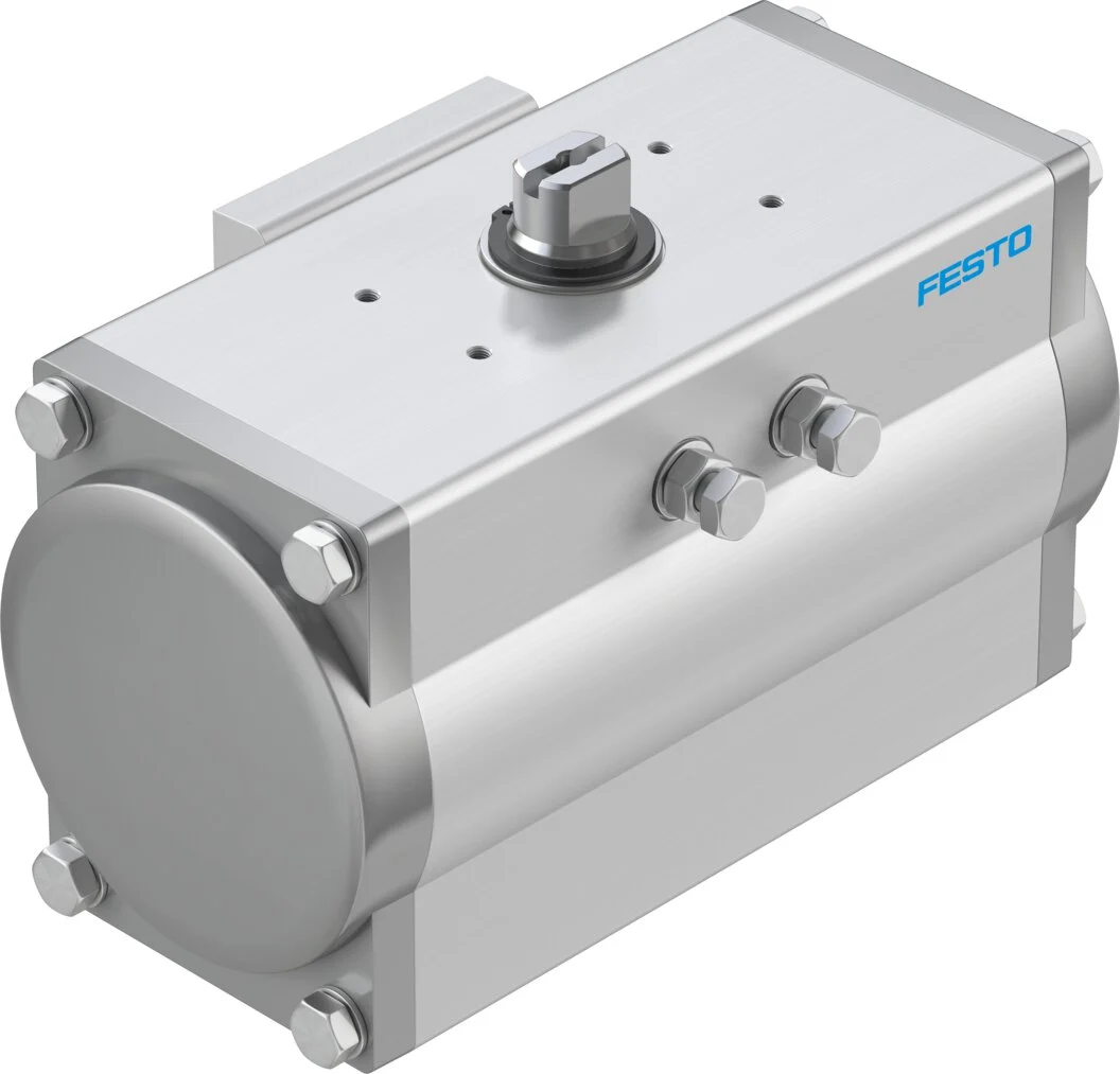
Family example: DFPD-120, part number 8042188
Festo’s 2026 data sheet for configurable family 8042188 lists rack-and-pinion construction, single- or double-acting operation, an ISO 5211 mounting interface and VDI/VDE 3845 accessory connections. Depending on configuration, rotation is 90–180 degrees and operating pressure is 2–8 bar. The family may include different flange arrangements, closing directions and hazardous-area options. These specifications do not mean that all DFPD variants share the same certificates or torque values; use the completed type code’s data.
When selecting an actuator, it is necessary to consider not only the nominal torque but also the breakaway, running, and seating torque values at maximum pressure differences, as specified by the valve manufacturer. Factors such as temperature, the fluid’s tendency to accumulate or crystallize, seal aging, and prolonged waiting times can all increase the required torque. The minimum air pressure guaranteed in the system should be taken into account, and losses in the regulator, hoses, cable glands, pilot valves, and the discharge pipeline should also be deducted. The appropriate safety factor should be determined in accordance with the recommendations of the process manufacturer and the valve supplier. An actuator that is too large for the application may place excessive strain on the valve stem and mechanical components.
Single-acting and double-acting actuator behaviour
A double-acting actuator uses compressed air in both directions of motion. The final position in the event of air or power loss depends on factors such as the load, leakage, the intermediate position of the pilot valve, and the process forces. Therefore, a double-acting system should not be designed with the assumption that it will “remain in its current position at all times.” In a single-acting spring-return actuator, air is used to generate motion in one direction, and the energy of the spring ensures the defined return position. By properly configuring the return direction, the actuator can exhibit either fail-close or fail-open behavior.
Fail-close is not always the safest option for such processes. If the interruption of the cooling flow poses a danger, fail-open may be necessary; in the case of feed lines to reactors, closure is required. For certain applications, staying in the final position or performing controlled discharge is preferred. The safe operating conditions must be determined through HAZOP, LOPA, or other relevant risk assessments. The direction of the actuator’s spring, the valve body design, the pilot valve, the air reservoir, the power supply, and the control logic must all be designed in accordance with these safety requirements. The marketing claims of a single component alone cannot serve as proof of the system’s overall safety performance.
Positioners: modulation and local feedback
The electro-pneumatic positioner compares the target signal with the actual position of the actuator-valve assembly. Based on any deviation, it supplies air to or releases air from the pneumatic chambers accordingly. For rotary and linear mechanisms, appropriate connection kits and detection ranges are required. The control signal should be in the range of 4–20 mA or 0–10 V; whether the positioner drives dual or single-acting actuators; the nominal air capacity; and the fault response behavior are all specified in the complete product description. If the direction of valve movement does not correspond correctly to the DCS signal, it can lead to serious process errors.
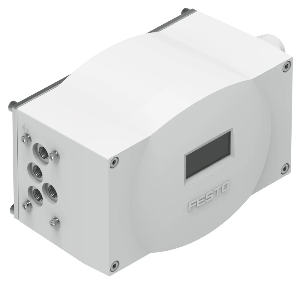
Variant example: CMSX-P-S-C-U-F1-D-50-A
Festo specifies product number 3929313 as a digital electro-pneumatic positioner with double-acting operation and a 0–100-degree sensing range. It operates at 24 V DC and supports 0–10 V, 0–20 mA and 4–20 mA setpoint inputs. Standard nominal flow is 50 l/min, operating pressure is 3–8 bar and the pneumatic connection is G1/8. These values apply only to this variant, not to CMSX codes offering 130 l/min, single-acting operation or different feedback options.
Before commissioning, ensure that the actuator moves freely and is connected in the correct direction. Positioner identification or initialization may move the valve through its full stroke, so first place the process in a safe condition. Verify zero and span against actual closed and open mechanical positions. Configure whether increasing the control signal opens or closes the valve according to the process definition. An excessively narrow deadband can increase wear and air consumption; an excessively wide one reduces control accuracy.
Limit switch boxes: position confirmation independent of commands
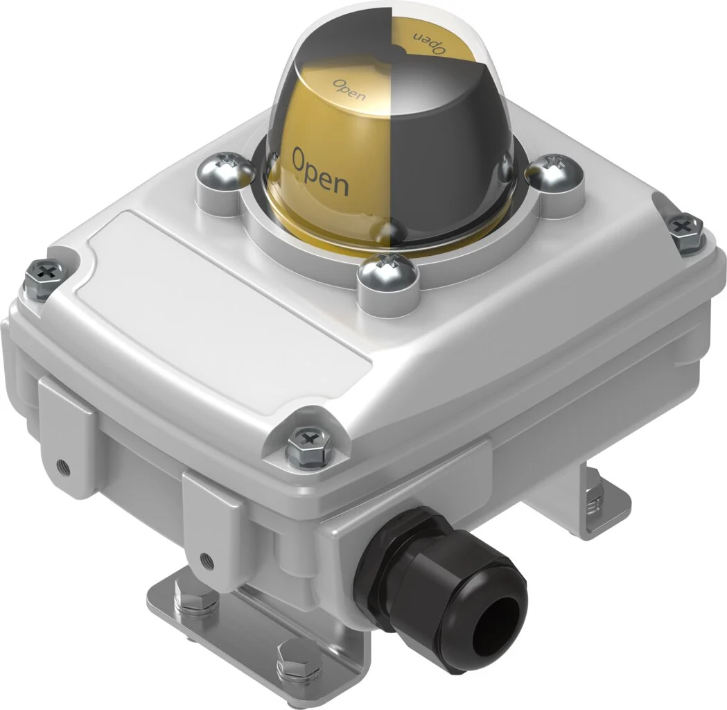
Limit switch boxes electrically indicate the extreme positions of the actuator shaft, especially in on-off control process valves. Visual indicators enable quick checks during on-site inspections; the mechanical, inductive, or other sensing elements inside the box transmit signals to the DCS/PLC. If the box complies with VDI/VDE 3845 standards, installation is simplified. However, it is still necessary to verify the shaft adapter, bracket height, rotation direction, and cam settings. Incorrectly matching the open and closed sensors can result in contradictory signals in the control room, even if the control system itself is functioning correctly.
Interpreting SIL data correctly
The data sheet for the SRBC variant with product number 3482808, dated August 11, 2026, lists the inductive measurement principle, the PNP normally-open output, and the SIL 3 classification based on the Eurocert certification. These specifications are not automatically applied to the entire SRBC family or to the complete valve assembly in which the device is installed. The safety integrity of the system is assessed based on the overall design of the components, including the sensor, cable, input module, logic controller, pilot valve, actuator, valve itself, and the testing setup. The failure rates, operating modes, common causes, diagnostic capabilities, and required periodic testing intervals must all be specified in the safety requirement documentation.
Furthermore, the position signal does not directly prove the internal integrity of the valve. Even if the stem is in the closed position, leakage may still occur due to damage to the seal or the presence of foreign objects. If a leak-free closure is critical, additional verification may be required through pressure, flow rate, or process analysis. The limit switch indicates the mechanical position; it must also be specified which measurement will be used to confirm the process outcome.
Pilot valves and pneumatic capacity
A pilot valve converts electrical or pneumatic commands into air flow in the actuator chambers. For single-acting and double-acting actuators, the appropriate path function, monostable or bistable behavior, coil voltage, NAMUR interface, manual override, flow rate, and exhaust configuration must be selected. Festo’s process pages list relevant product families such as VSNC, VOFC, VOFD, and VOFI in this context. However, the certification for use in hazardous areas or the compliance with SIL standards must be verified based on the specific variant selected and the application architecture, rather than the product family itself.
The operating time of an actuator is not determined solely by its torque. The actuator’s size, supply pressure, pilot valve flow rate, hose diameter and length, fittings, speed control components, and exhaust suppressors all affect the filling and emptying times. Too rapid closing can cause hydraulic shocks or valve wear; too slow movement, on the other hand, may exceed the safety requirements of the process. Speed control must be adjustable in both directions and measured at the minimum system pressure during acceptance testing.
In the event of a power loss, the return movement of the pilot valve’s spring is examined separately; in the case of a loss of air pressure, the direction of the actuator’s spring movement and the valve’s response once air pressure is restored are also analyzed separately. Even if a bistable valve retains its last electrical command, the actuator’s behavior may still change due to a loss of air pressure. To prevent unexpected automatic movements during re-energization, the control logic must be designed in conjunction with soft pressure-boosting mechanisms and operator procedures.
ATEX conformity depends on the complete configuration
For explosive atmospheres, the facility must first determine the category of the area (gas or dust), the temperature class, the equipment category, and the ambient temperature. Subsequently, the most suitable variant of each electrical and non-electrical component must be selected to comply with these classification criteria. Some configurations of the DFPD series, as well as certain limit switches and pilot valves, may offer different ATEX or IECEx options; however, this does not mean that the standard variants can be used in explosive areas. The certification number, marking, special operating conditions, and permitted accessories must all be verified before the product is delivered.
The protective measures for a positioner or sensor enclosure are not the same as those designed to prevent explosions. Class Ex i, Class Ex d, or other different protection methods require different types of cable glands, barriers, grounding systems, and maintenance procedures. The product label, conformity statement, certification documents, and instruction manual must be retained in the as-built documentation. Mechanical factors such as painted surfaces, static loads, impacts, heat transfer due to process temperatures, and environmental corrosion also need to be considered in the field risk assessment.
Air preparation, materials and environment
Provide compressed air meeting the manufacturer’s particle, water and oil classes for stable positioner and pilot-valve operation. Size the filter-regulator for peak flow of simultaneously moving valves as well as normal consumption. Assess regulator distance, supply-line volume and condensation/freezing risk at low temperatures. In corrosive atmospheres, evaluate suitable body coatings, stainless connections and pilot-valve rebreathing arrangements at product level.
The material of the valve in contact with the process fluid and the environmental resistance of the pneumatic actuator are two different aspects to consider. Normally, the actuator does not come into direct contact with the process fluid; however, it may be exposed to valve stem leaks, cleaning chemicals, salty environments, or UV radiation. The ambient temperature must remain within the operating range of both the actuator and its electronic components. If the process temperature is transmitted through the stem and mounting kit, heat insulation or extension measures may be required.
Digital integration and diagnostics
In a control system, parameters such as position command, actual position, open/close status, movement time, air pressure, and fault status should be labeled as separate signals. By distinguishing between issues like “valve failure” and conditions such as low air pressure, open-time overrun, close-time overrun, conflicting limits, position deviation, and communication loss, maintenance efforts can be directed more efficiently. For analog signals, abnormalities in the signal line or values outside the specified range can be detected; for digital communication, device identity, status codes, and timestamps can provide valuable information.
The trend in the valve’s movement time can be an early indicator of increased friction, low air pressure, a clogged filter, or actuator wear. However, this data should not be interpreted in isolation. Process pressure, product temperature, and the conditions under which the valve moves for the first time after a long period of inactivity can all affect these measurements. When establishing a maintenance indicator system, it is essential to compare similar operating conditions and identify key parameters that can help reduce false alarms.
Commissioning and acceptance testing
- Document review: The complete code of the valve, actuator, mounting kit, pilot valve, positioner, or limit switch is compared with the provided certificates and diagrams.
- Mechanical control: The direction of movement, the axis of connection, the stops, the shaft adapter, the bolt torques, and the safe manual operation are all verified.
- Pneumatic control: Air quality, regulators, port connections, hose diameter, leakage, exhaust emissions, and operating duration are all examined.
- Electrical control: It is necessary to verify the coil voltage, PNP/NPN configuration, analog scale, grounding, cable glands, and hazardous area barriers.
- Function testing: The opening/closing command, local indicator, feedback, modulation direction, and control loop are all tested under actual operating conditions.
- Fault test: With safe procedures in place, phenomena such as power loss, signal interruption, low pressure, and restart behavior can be observed.
The opening and closing times should be measured at the minimum plant pressure, and preferably under the most challenging process conditions. At the modulation valve, the actual position is recorded at the settings of 0%, 25%, 50%, 75%, and 100%; the behavior regarding hysteresis and direction changes is also evaluated. If necessary, the loop settings are adjusted in conjunction with the stability of the process variable. Tests for spring return or emergency shutdown should not be conducted without specialized procedures specifically designed for the equipment and the process in question.
Checklist for quotations and bills of materials
- Process fluid, line pressure, pressure difference, temperature, and environmental corrosion conditions.
- Valve type, manufacturer, size, stem/flange interface, rotation angle or stroke, and torque/force curve
- Opening/closing action or modulation function, normal operating time, and cycle frequency
- Minimum-normal-maximum air pressure, air quality class, current flow rate, and hose length.
- Single- or double-acting actuators; fail-open, fail-close, or other predefined functions in the event of power or air supply failure.
- Pilot-valve function, flow, NAMUR interface, coil voltage, manual override and exhaust arrangement
- Limit switch, sensor type, output, connector/cable gland/fitting, local indicator, and cable layout.
- Positioner signal range, actuator type, air capacity, feedback, and communication requirements
- ATEX/IECEx zone and marking requirements; SIL target, safety function and test interval
- Mounting kit, fittings/tubing, regulator, pressure gauge, silencer, isolation and spare-parts list
Once this data set is complete, Festo’s process automation components can be selected not as individual catalog items, but as measurable valve units. The appropriate actuator moves the valve with the required force and within the necessary time; the pilot valve controls the flow of air; the positioner or limit switch provides reliable feedback to the control system. Risk assessments, certifications, and acceptance tests ensure that the unit not only functions independently but also performs the specified process and safety functions.