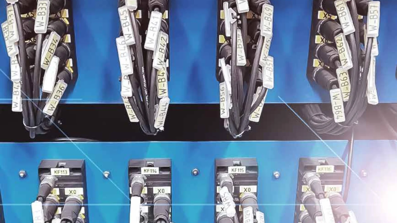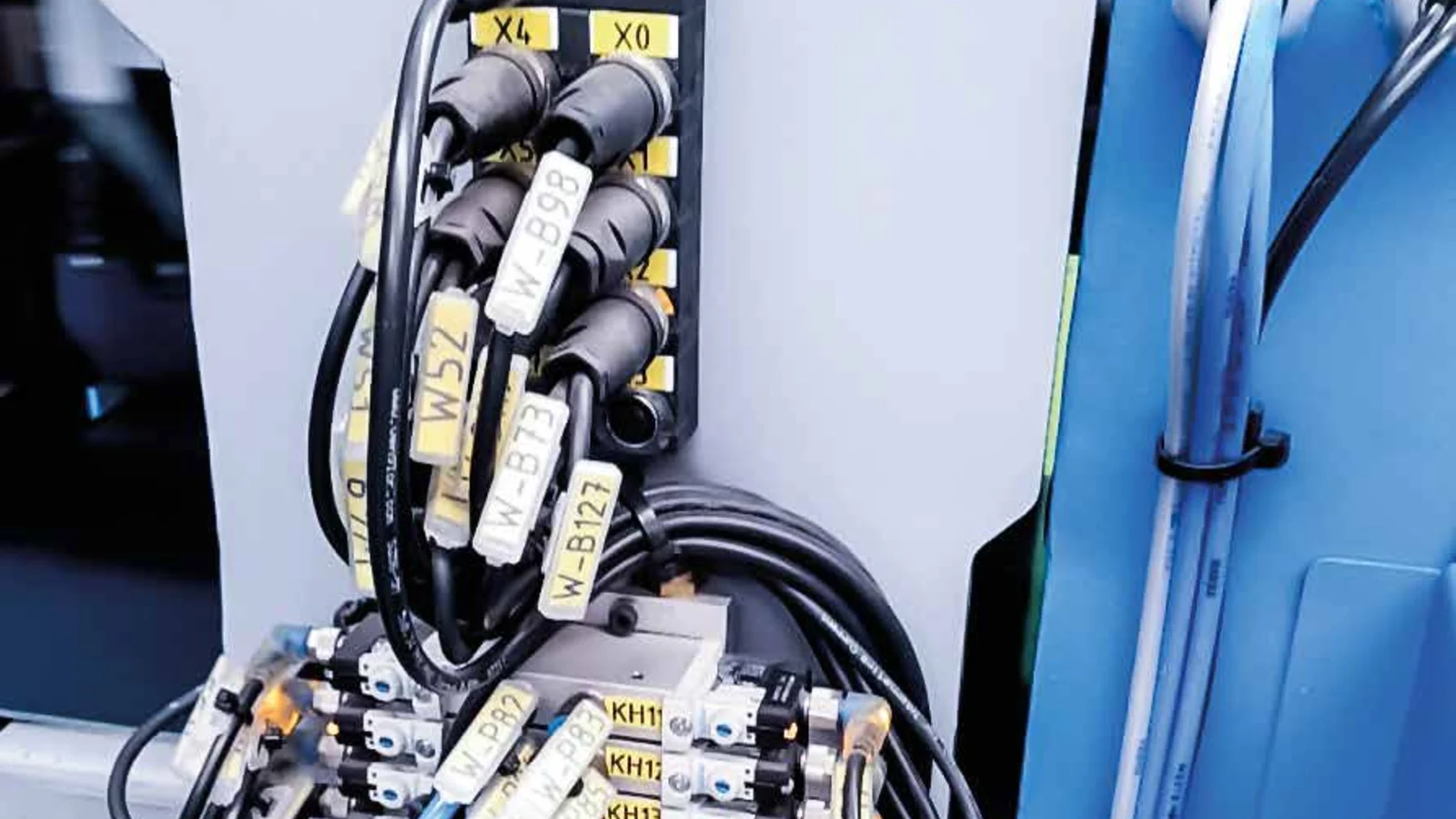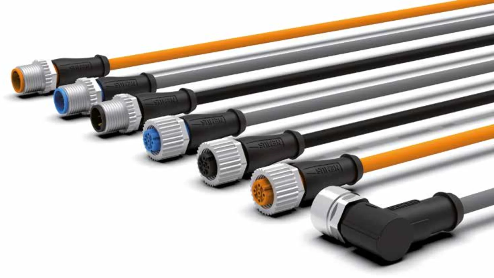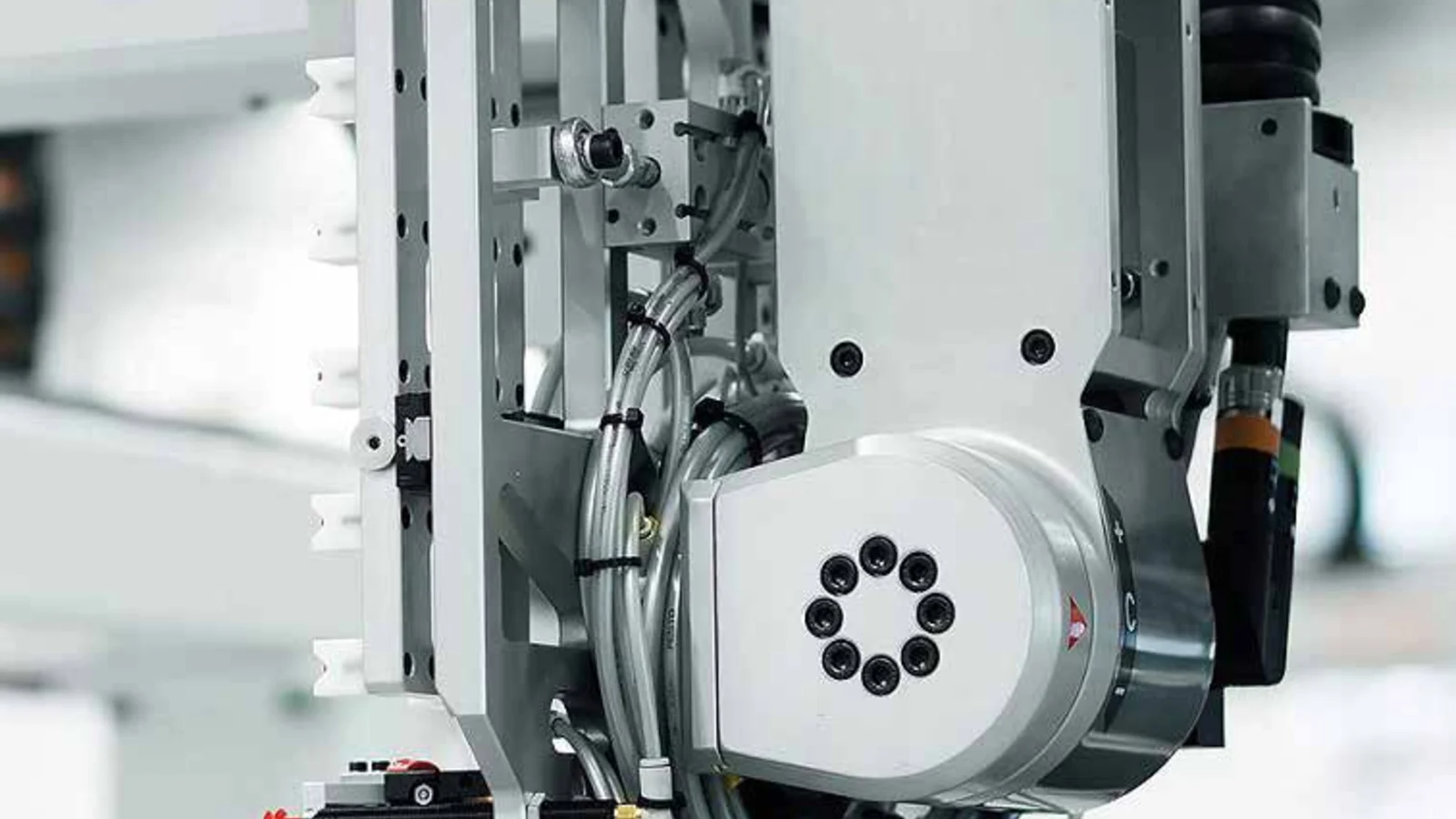
A custom connection solution is not merely about producing a standard cable in different lengths. The machine’s interface requirements, the need for M8 or M12 connections, the type of male-to-female connector configuration, whether the body is straight or angled, the number of contacts, the type of cable sheath, the movement profile of the component, the environmental conditions, and the maintenance considerations—all these factors must be taken into account within a single product definition. Nemus’ official catalog, which includes M8-M12 transition cable sets as well as PVC, PVC+, and PUR sensor cables, helps to define this concept precisely. While the catalog specifies certain connector configurations and standard lengths within the M12-M8 family, the feasibility of any other combination of connectors, pins, or cable bodies must be separately confirmed by Nemus. This guide explains which technical details need to be clarified before requesting a custom length or any non-catalogue-specific requirement, and it outlines how a proposal can be transformed into a reliable connection specification.
When are application-specific connections required?
A standard-length, two-ended cable with the same body dimension can be used for connecting multiple sensors. However, in cases where the sensors on the machine use M8 connectors, while the distribution or control system uses M12 connectors; when there is no space available for a straight cable body; when the standard length results in unnecessary extra cable loops; or when different types of cable sheaths are required for continuous motion, a custom cable assembly may be more appropriate for the specific application. The purpose of such a custom solution is not to increase diversity but rather to ensure that the connection method is compatible with the device and its operating conditions.
The fact that a product is specialized does not mean that the basic engineering principles no longer apply. Parameters such as current rating, voltage, conductor cross-section, temperature range, connection cycle, IP rating, and mechanical specifications of the cable remain relevant. Therefore, a request should not simply state something like “one end is M12, the other end is M8, length: five meters.” Instead, it is necessary to specify details such as the gender, coding, number of contacts, orientation of the body, and pin alignment for both ends; for the cable, details like the conductor configuration, sheath type, color, length, and required movement range should also be provided. A clear and complete description reduces the risk of mis-matching and the need for on-site adapter adjustments. If the request deviates from the standards specified in the catalog, such a technical description serves not as an assertion that Nemus can produce such a product, but rather as essential information required for evaluating its feasibility.
Nemus M12-to-M8 cable assemblies
Nemus’ official catalog includes A-series cable sets with three or four contacts, designed to provide a transition between M12 and M8 connectors. The documented connection configurations consist of M12 male connectors at 0° or 90° angles, paired with M8 female connectors at 0°. The cable options are available in PVC, PVC+, and PUR materials. Product tables provide samples measuring 2, 5, and 10 meters, as well as custom lengths upon request. This enables the connection of the two different device interfaces specified in the catalog without the need for any additional accessories. If a different gender combination is required, or if M8 connectors need to be mounted at a 90° angle or with other terminal configurations, it is advisable to consult Nemus directly regarding such options.
In the official catalog, for this product family, the maximum specifications are: a conductor cross-section of 0.25 mm², a current rating of 4 A per contact, and supply voltages of 50 V AC or 60 V DC for three- or four-contact configurations. The IP65, IP66K, and IP67 ratings are applicable only if the connections are properly mated and tightened to the corresponding counterpart parts. For the PUR version, the technical specifications include an operating temperature range of −40 to +80 °C, a cycle life of 4–6 million cycles under dynamic bending conditions at a bend radius of 10 times the cable outer diameter, a maximum acceleration of 30 m/s², and a speed capacity of up to 240 m/min. It should be noted that these values do not guarantee the same service life for every specific application; the overall product performance must be assessed in conjunction with the mode of operation, bending radius, and the manufacturer’s test conditions.
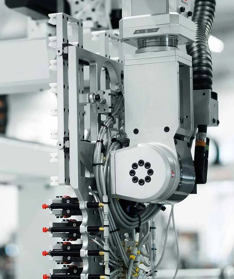
First step: fully specify both connection interfaces
Custom assembly design begins not with the cable itself, but with the two devices that need to be connected. The technical drawings of sensors, actuators, distribution modules, or control panel interfaces contain information regarding the connector size and coding system. Designations such as M8 or M12 indicate the mechanical family to which the connector belongs; electrical compatibility also depends on the number of contacts and their functions. The male-to-female connection must be established with the correct orientation of the contact surfaces. The pin arrangement, as inferred from a device’s photograph, may actually be reversed when viewed through a mold drawing or the cable’s exterior.
The next decision concerns the shape of the connector body: whether it should be straight or at a 90-degree angle. An angled body can reduce the overall protrusion in confined spaces and direct the cable in the desired direction. However, if the angle of the body is incorrect, there is a risk of damaging the cable during installation. The layout of three-dimensional machinery, the presence of protective covers, the proximity of sensors, and the accessibility of maintenance tools must all be taken into consideration. Whenever possible, the measured dimensions of the connection area should be carefully compared with the technical specifications of the connector.
Cable construction: differences between PVC, PVC+ and PUR
The Nemus catalog categorizes sensor cables into three main groups based on their application. PVC is the standard choice for fixed applications. PVC+ is designed for cost-effective, dynamic applications; according to the catalog specifications, it can handle 3–5 million cycles, has a dynamic bend radius of 10 times its outer diameter, a maximum speed of 180 m/min, and a maximum acceleration of 10 m/s². PUR, on the other hand, is advertised as offering higher dynamic performance, particularly for robotic applications. Its specifications include 4–6 million cycles, a dynamic bend radius of 10 times its outer diameter, a static bend radius of 7.5 times its outer diameter, a maximum speed of 240 m/min, and a maximum acceleration of 30 m/s².
In terms of temperature range, PVC and PVC+ are generally specified to operate between −15 and +80 °C, while PUR is specified for a range of −40 to +80 °C. PUR is also described as being halogen-free. In Nemus’s catalog, the “TPE-0 high-temperature sensor cable” is listed as having a temperature range of −40 to +140 °C and supporting motion data. However, the terminology for TPE-0, PVC, and PUR on the same page is inconsistent; therefore, the material used for the sheath, the relevant certifications, and the full product code must be confirmed in accordance with the latest technical specifications.
| Cable group | Application guidance in the catalogue | General catalogue data | Selection considerations |
|---|---|---|---|
| PVC | Fixed connections | −15…+80 °C | Do not assume suitability for continuous motion |
| PVC+ | Economical and dynamic use | 3–5 million cycles; 180 m/min; 10 m/s² | The bending radius and the arrangement of the support members must be confirmed. |
| PUR | Higher dynamic performance and robotic applications. | 4–6 million cycles; 240 m/min; 30 m/s²; −40…+80 °C | Torsion, the chemical environment, and the actual motion profile also need to be taken into consideration. |
| The option labeled TPE-0 | High-temperature requirements | On the relevant catalog page, it is specified as −40…+140 °C. | Due to the use of the terms TPE-0/PVC/PUR on this page, it is necessary to confirm the meaning of “sheath” and the current codes used by the manufacturer. |
The number of cycles alone does not determine the appropriate cable selection. The actual service life is influenced by factors such as the length of the cable carrier, bending radius, travel distance, acceleration profile, the degree of filling within the bundle, friction between the cables, and the strain-relief arrangement at the connection ends. The torsion generated in a robotic arm is not equivalent to the repeated bending that occurs in a linear energy chain. The application specifications must include details such as the number of axes, direction of motion, cycle frequency, daily operating hours, and expected total service life. If the field performance differs from the results of the manufacturer’s catalog tests, additional compatibility assessments are required.
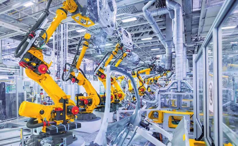
Calculating custom cable lengths correctly
Excessively long cables do not serve any legitimate safety purpose. Uncontrolled loops inside the conduit can become tangled, rub against machine surfaces, or add unnecessary weight to sensor connections. On the other hand, excessively short cables can create pulling forces at the movement endpoints, hindering maintenance operations. The required cable length must be calculated by taking into account the fixed path distance, the movement geometry of the conduit, the service margins at both ends, the internal routing within the control panel, and the dimensions of the connector housing itself. The measurement should be based on the actual cable route, rather than a straight-line distance between two points.
In series production, the tolerance range should be specified only after the length measured on the first sample is confirmed as acceptable. It must be indicated in the drawing which reference points the cable length is measured from—whether it is the connector face, the end of the body, or the cable outlet. For bodies with an angled design, the outlet direction should also be shown in the drawing. If the same cable assembly is to be used for different machine models, it is more cost-effective to compare the service and inventory costs of the various models rather than selecting the one with the longest required length.
Pin assignments and electrical limits
It should not be assumed that the pin numbers will continue in the same order during the transition from M12 to M8. A matching table must be provided to show how the pins on the source device—such as the power supply, common terminal, switching output, and any additional functions—correspond to the pins on the target port. For products with three or four contacts, the wire colors used should be confirmed on the technical drawings and samples. If a different wiring configuration is required than what is listed in the catalog, its feasibility must first be verified by Nemus. Any approved variation must clearly differ from the standard connection scheme, and this change should be indicated on the product label.
The current and voltage ratings are determined in conjunction with the cable’s carrying capacity, contact configuration, operating temperature, and the requirements of relevant standards. The values of 4 A per contact and 50 V AC/60 V DC specified in Nemus’s official M12-M8 catalog tables serve as references for corresponding three- or four-contact assemblies and should not be applied to other product groups. Similarly, the UL or CSA certification information provided for the cable material does not imply that the entire finished cable assembly is automatically certified. If project approval at the product level is required, the full scope of the certification must be specified during the bidding process.
Protection, environment and connection life
The IP rating of a molded connector cannot be determined solely by examining its body. In Nemus product specifications, the IP65, IP66K, and IP67 ratings are provided in conjunction with the corresponding connector to ensure a secure and proper connection. Inappropriate device sockets, dirty seal surfaces, loose nuts, or mechanical stresses affecting the connection can all compromise its protective capabilities. For unused ports, it is essential to use appropriate protective caps as part of the cleaning and maintenance procedures.
The definition of “environment” encompasses far more than just water and dust. Substances such as oil, cooling fluids, cleaning chemicals, welding sparks, UV radiation, ozone, hot sparks, vibration, and electromagnetic interference are all considered separately. For signals that require cable shielding, or for applications involving power cables in close proximity or highly sensitive analog measurements, the standard structure of sensor cables may not be sufficient. In cases where the requirements exceed Nemus’ standard product range, suitability must be assessed technically in conjunction with the manufacturer.
Technical approval for a non-catalogue request
- Request form: Devices at both ends, their interfaces, electrical data, as well as environmental and motion profiles are all recorded.
- Product description: The M8/M12 specification includes details such as size, gender, coding, contacts, body orientation, cable type, color, and length; additional elements not listed in the catalog can be produced upon verification of their feasibility.
- Technical drawing: The orientation of the terminals, pin assignments, measurement references, tolerances, and label contents are all made available for approval.
- Sample: The first prototype is tested for mechanical compatibility with actual devices, as well as for the continuity of pins, orientation, routing, and accessibility for maintenance.
- Test plan: Continuity, short-circuiting, insulation, and the required application tests serve as the criteria for acceptance.
- Series-production approval: The approved sample is matched with the drawing revision and product code, and the change management process is initiated.
- Field feedback: By monitoring commissioning and maintenance data, the route, fixing measures, or product specifications can be revised as necessary.
This process ensures that non-catalog requests remain within the scope of the purchase specifications; however, it does not replace Nemus’s approval of the product’s manufacturability and commercial suitability. The mutual verification of the drawings and pinouts by both parties reduces the risk of confusion between similar but electrically different cable assemblies. In mass production, the results of electrical tests must be traceable to specific product batches. The label must clearly indicate the product code, length, and, if required, the customer reference number. Whenever a modification request is received, it is essential to record which machines have been using the old and new versions of the component.
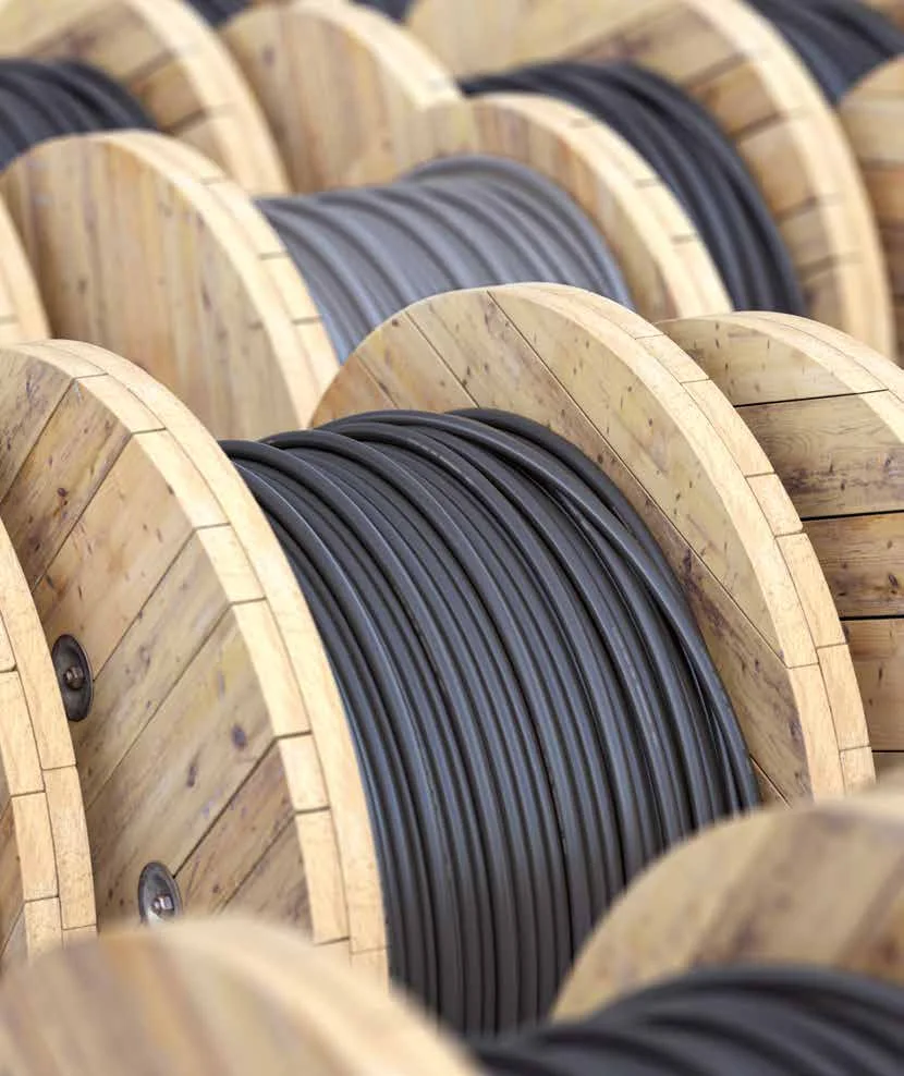
Information required in the purchasing specification
- The connection interface, which has been verified in accordance with the manufacturer’s technical drawings of both the source device and the target device.
- For each connectors, the options include M8/M12, A-code designation, male/female configurations, various numbers of contacts, as well as straight or 90° orientation.
- Numbered pin mapping table, conductor colors, and signal functions
- Voltage, contact current, conductor cross-section, number of wires, and the need for a shield.
- Environmental factors that determine whether to choose PVC, PVC+, PUR, or a special temperature-resistant solution.
- Motion type, bend radius, speed, acceleration, cycles, torsion, and daily operating time
- Length, a reference for measuring length, tolerances, cable color, as well as the content of the label.
- Matching and mounting conditions under which the IP target will be valid.
- The required standards, certification scope, test reports, sample approvals, and delivery documents.
The value of application-specific connection technologies lies in their ability to eliminate the need for adapters in the field. When properly designed, they can reduce installation time, eliminate the need for excess cables, prevent incorrect connections, and speed up product maintenance and replacement processes. However, if the requirements are not clearly defined, such custom assemblies may lead to greater dependence on these products and increased inventory complexity. At the project initiation stage, it is essential to carefully consider which variants are truly necessary, the annual usage volume, the required number of spare parts, and any potential future changes to the machinery.
The Nemus product family offers practical solutions for this application, featuring M8 and M12 connectors, M12-M8 transition connectors, and various cable configurations. The final product selection should not be based solely on a general catalog table, but rather on the specific product code selected, the latest technical specifications, approved drawings, and actual application requirements. In this way, the connection technology becomes an integral part of the electrical design, mechanical layout, and maintenance plan, rather than an additional detail added later on.