Variable load geometry
Fixed shelf spacing wastes vertical volume when parts, tools and fixtures have different heights and weights.
A VLM uses a central lift moving between two tray columns to automatically deliver the selected independent tray to the access opening.
Explore the solution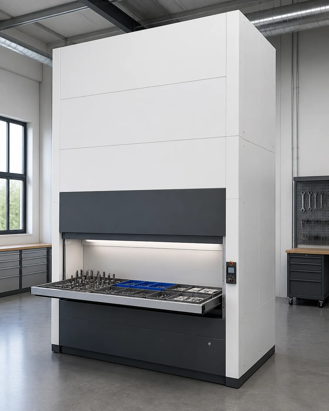
Fixed shelf spacing wastes vertical volume when parts, tools and fixtures have different heights and weights.
Manually moving heavy trays and searching across racks increases access time and physical strain on operators.
Manual location and consumption records make it difficult to know where valuable tools and MRO parts are and who is using them.
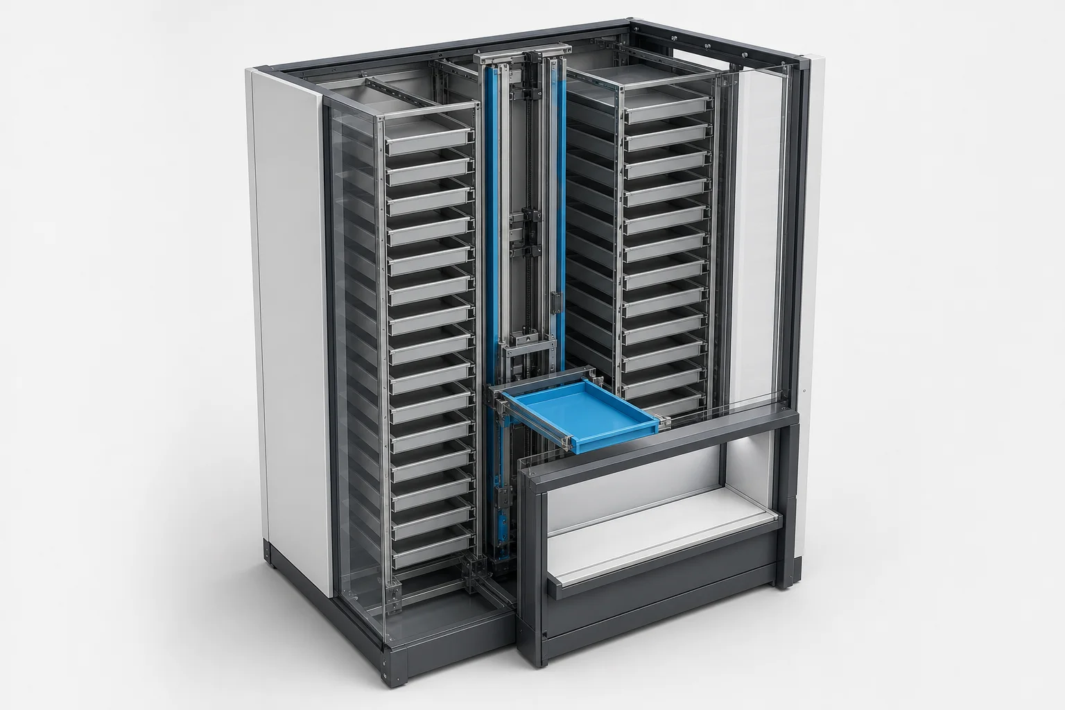
VLM trays remain in individual locations across two storage columns. The central lift retrieves only the tray requested by the software and presents it at the operator access opening. This architecture accommodates different load heights within one enclosure and turns building height into usable storage volume.
The values below are ranges and upper limits for the reviewed VLM configuration. Final sizing depends on tray dimensions, load distribution, building geometry and access-opening requirements.
Sizing note: Per-tray and total-load limits must be evaluated together. Capacity depends on load distribution across the tray and the selected configuration.
The decision should consider SKU dimensions and weight, access frequency, total inventory, building geometry, ergonomics and integration targets together.
Each tray is requested independently and the central lift moves only the selected tray. This approach stands out for loads of different heights and weights and for multi-floor access scenarios.
You are viewing this pageChain-connected carriers rotate together. This approach stands out for ergonomic access to frequently used small and medium stock with similar dimensions.
Explore the other technology ↗We separate the standard architecture from optional equipment and define the project around load, access, safety and integration requirements.
Inventory not involved in the task remains stationary; the central lift brings only the selected tray to the access opening.
Bins, fixed or movable dividers and special fixtures can create an application-specific internal tray arrangement.
Material comes to the operator, reducing ladder use, walking between racks, reaching and manual handling of heavy trays.
Internal or external, single- or dual-level access openings can be engineered across floors or on opposite faces.
User, product, location, picking and replenishment movements can be recorded in inventory-management software.
The existing WMS and automated picking or replenishment equipment can be connected through defined data and task flows.
Browser-based inventory software provides a control layer for product and location mapping, picking and replenishment lists, stock and expiry-date checks, dynamic inventory and system self-diagnostics. WMS data scope and update behaviour are defined within the project.
A product or work list arrives from the local interface or a higher-level system.
→Inventory software matches the product to its tray or carrier location.
→The VLM transfers the tray; the VCM positions the carrier loop.
→The picking or replenishment result becomes a stock movement and transaction record.
Record dimensions, weight, access frequency, quantity and storage conditions for every material group.
Model tray dimensions, dividers, load distribution and dynamic use of free height together.
Check clear height, floor loading, access openings, fire strategy and maintenance clearances.
Specify user, product request, barcode, work-list and transaction-confirmation steps.
Define the exchange of stock movements, product masters, picking lists and replenishment lists.
Validate load, cycle, safety, fault recovery and user scenarios with real products.
Manage cutting tools, dies, fixtures and measuring equipment in independent trays.
Keep critical spare parts of different sizes under controlled access with recorded movements.
Hold work-in-process and heavy components in a compact buffer beside the line.
Preserve location and transaction history for electronics, laboratory or project-specific materials.
Customer and facility information has been anonymized to meet confidentiality obligations.
Share load profiles, throughput targets and space constraints so the right architecture can be assessed.
Request a storage and flow analysis Your request is routed directly to the relevant engineering team.
Engineering confidence with Oskon.
Leave your details and our expert engineers will contact you for a preliminary consultation tailored to your needs.