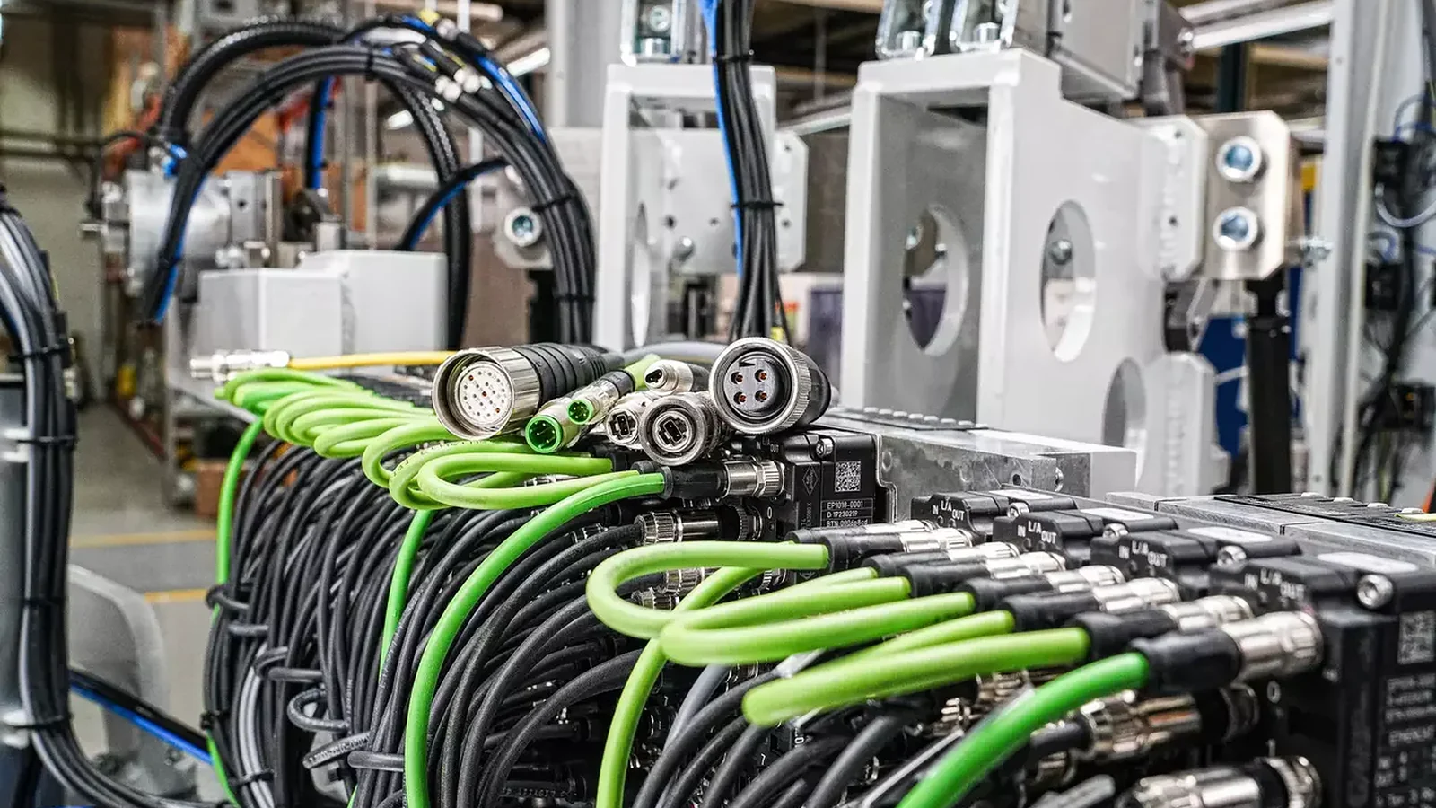
System cabling eliminates the need to prepare cables individually in the field. Instead, it establishes a cable architecture in which the connection functions are predefined, the ends are equipped with appropriate connectors, and the cables are ready for testing. HARTING’s portfolio includes system cables for power and signal transmission, featuring circular connectors, Han industrial connectors, and I/O-oriented designs. For data transmission, it offers circular, network, Han, and fiber optic cable sets. The pre-configured connections simplify the reconnection of machine modules during production, on-site installation, commissioning, and maintenance.
Standard system cabling and customized connection solutions are not the same thing. In the case of standard cable assemblies, the two ends, contact arrangement, cable structure, and length are determined by a specific HARTING product number or predefined configuration. For customized solutions, various components such as special pin configurations, panel boards, intermediate PCBs, robotic cables, or application-specific test kits are developed specifically for a particular project. A sound design process begins with evaluating standard products; only when these cannot meet the requirements of a specific application will specialized engineering be required.
What does standard system cabling offer?
Pre-assembled cable sets enable the controlled production of connector assemblies and facilitate field connections using a plug-and-play approach. HARTING offers a range of pre-assembled cable solutions for power, signal, and data transmission. Its product page highlights features such as plug-and-play installation, 100% tested components, and connections that are resistant to damage caused by handling on molded cables. These claims are valid only when the correct product is used in accordance with the manufacturer’s instructions.
Preassembly can reduce the likelihood of errors, but it cannot automatically correct incorrect pin assignments or wrong product selections in the system design. Just because the mechanical interfaces of the ports match does not mean that their electrical functions are also compatible. Before placing an order, both ends of the component should be verified using the device data sheet, I/O list, and one-line power diagram. During commissioning, the product label, cable label, and the connection number on the drawing must all refer to the same component.
In modular machines, system cables facilitate the testing of production modules in the factory and their subsequent connection at predetermined points in the field. Replacing a faulty module or cable set with one of the same product number can significantly reduce maintenance time. For this to be possible, the cables must be located in easily accessible areas, the locking mechanisms must face the service area, and the spare parts list must include all necessary components for a complete configuration. Simply designating a connector as a spare part based only on its family name is not sufficient.
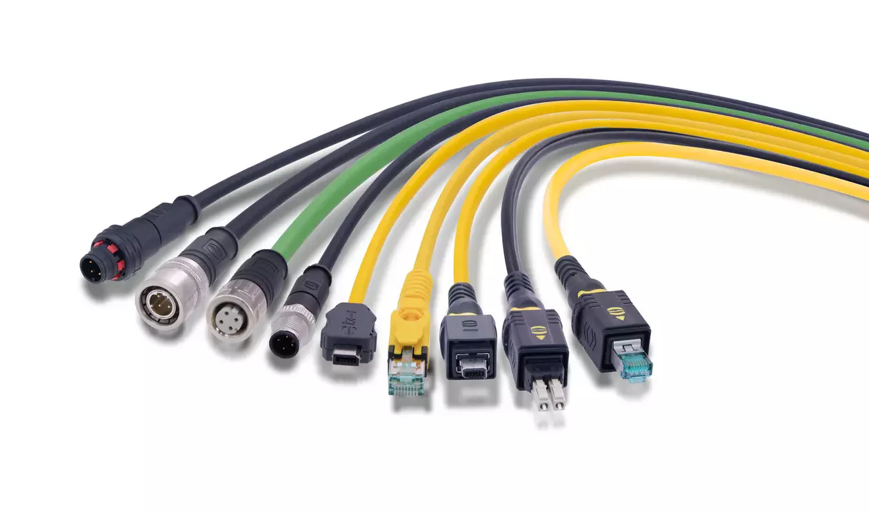
Distinguish pre-assembled, field-assembled and customised solutions
| Approach | Suitable application | Point to check |
|---|---|---|
| Standard pre-installed cable | The connectors, cables, and their lengths are all pre-matched with the finished products. | Product model number, two terminals, and device pin layout |
| Configure the system cable. | Within the available options, the desired length or combination of connector types is selected. | Configuration output, available options, and data page |
| Connector installed in the field | Routing and final length are determined at the installation site | Terminal kit, cable diameter, cross-section, shielding, and mounting quality |
| Customized cable assembly | In addition to the standard options, pinning, material selection, or testing may be required. | Drawing, prototyping, validation, revision, and minimum project requirements. |
| Special cable harness and interface | Multiple branches are required, along with a control panel, a PCB, or a robot package. | Full responsibility for the electrical, mechanical, and lifecycle aspects of the entire system. |
Power and signal system cabling
In terms of power and signal transmission, three main types of cable assemblies emerge: those equipped with metric circular connectors, Han industrial connectors, and I/O system cables. For circular connectors, M5 and M8 sizes are commonly used for compact sensor connections; M12 is preferred for various signal, data, and power coding applications; while M17 and M23 are suitable for applications requiring more contacts, especially in drive systems. These are general guidelines for selection. Specific voltage ratings, current capacities, coding details, and IP information can be found on the data sheets for each product model.
Han system cabling establishes power connections, multi-pin signal transmissions, or data links through robust rectangular connectors, with a range of options ranging from compact series like Han 1A to larger-bodied, modular designs. The insert, contacts, body, cable outlet, and locking mechanism must be selected as a compatible set. One-ended cables can be terminated inside a control panel or device, while two-ended cables provide a direct connection between two designated interfaces.
I/O system cabling can be used to transfer multi-pin connections on a control card, intermediate module, or device via pre-made cables. HARTING’s portfolio includes product groups featuring various interfaces such as ix Industrial, PushPull, and D-Sub. The term “I/O” here does not imply universal pin compatibility with all PLC brands. The card model, connector type, number of contacts, common potentials, as well as the layout of shielded and unshielded terminals must necessarily match the current manufacturer’s specifications.
Product example: a pre-assembled Han 1A power cable
The product with the number 33 40 040 0202 050, “Han 1A OM 3+PE +latch m/ - PVC 5m”, is a concrete example of a system cable. According to HARTING’s product page, this is a 5-meter PVC cable set with one end pre-assembled with a Han 1A male connector and a molded connection, while the other end remains open. The cable features a four-conductor design with a cross-sectional area of 4 × 2.5 mm², includes three power contacts and one protective conductor contact, is equipped with a plug-in latch mechanism, and has a cable diameter of 9.2 mm.
For the same product, the nominal current of 16 A and the nominal voltage of 400 V have been specified. The maximum operating temperature ranges are −40 to +80 °C when the product is at rest, and −15 to +80 °C when it is in motion. IP65, IP66, and IP67 apply when mated; the page specifies cable-to-cable mating for IP66/IP67. It is further required that the cable not be connected or disconnected while under electrical load, and that the installation must be carried out by a qualified electrician. These specifications apply exclusively to this product number and should not be automatically extended to other Han 1A cables.
Data and network system cabling
In industrial Ethernet applications, the entire transmission channel is just as important as the type of connector used. HARTING’s network system cabling includes interfaces such as RJ Industrial, ix Industrial, M12, T1 Industrial, and preLink, as well as various copper cables and pre-assembled cable sets. Fiber optic system cables, on the other hand, represent a separate solution option for topologies that require resistance to electrical interference, long-distance communication, or galvanic isolation. When making a selection, it is important not to confuse the protocol name with the physical layer characteristics of the cable.
When selecting Ethernet cables, factors such as the target data speed, channel category, number of pairs, shielding structure, industrial protocol profile, cable length, and number of intermediate connections need to be considered together. Even if a single cable segment meets high-performance standards, if the connectors, panel connectors, and field connectors have lower performance, the overall performance of the entire system will not be comparable. Shielding continuity, 360-degree contact, equipotential bonding, and proper separation of power and data cables are all crucial for reducing EMI interference. In applications involving mobile robots or cable carriers, data performance must be verified under actual operating conditions.
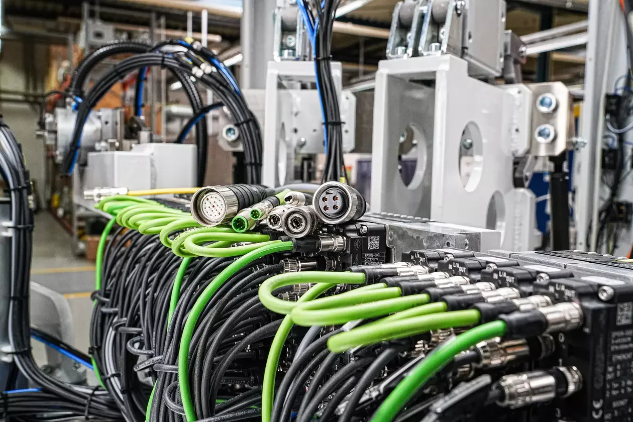
The preLink system represents a field-installation approach that separates the cable termination block from the connector and socket. HARTING states that the same preLink termination block can be easily attached and removed from different preLink components, enabling its use in IT, building automation, and industrial applications. This design provides flexibility at the points where the cable needs to be prepared in the field. However, it is essential to select the appropriate cable, termination device, pin configuration, shielding, and target network performance in accordance with the system documentation.
Moulded connectors or field termination?
In a pre-manufactured cable assembly, the connector and the cable section are integrated during production. HARTING explains this design approach with the objectives of providing secure cable retention, enhanced bending protection, and extended service life in harsh environments. Factory testing ensures consistency, while on-site installation procedures are simplified. However, it is essential to accurately measure the cable length and routing in advance; in many cases, damaged ends must be replaced by an entire cable assembly rather than being re-terminated on-site.
Field-mounted connectors enable the termination of cables after they have been run through a facility. These may be suitable for projects where the existing conduit, narrow passages, or fixed lengths are predetermined during installation. However, the cable outer diameter, conductor cross-section, contact and termination technologies, shield connections, stripping dimensions, clamping torque, and sealing measures are all subject to the control of the installer. Installation personnel must use the appropriate tools and follow the correct instructions; if continuity and data integrity are required, channel testing must be performed.
The two methods can be used together in the same facility. For mass-produced machine modules, pre-manufactured and tested cables can be used; in the field, preLink connectors or suitable field-mounted connectors may be preferred depending on the specific application. The decision should not be based solely on the initial product cost. Factors such as installation time, error correction, testing equipment, training requirements, spare parts availability, service accessibility, and downtime impacts should also be taken into account when calculating the total cost.
Select cable construction for the application
HARTING’s range of bulk cables includes copper cables, fiber optic cables, and hybrid cables that can transmit both power and data using the same structure. For copper cables, the number of conductors, the cross-section, the conductive material composition, the shielding, and the outer sheath all determine both the electrical performance and the mechanical durability. A fixed cable tray, a cable carrier, a robotic axis that rotates, and a stationary service ring do not belong to the same category of mechanical components. If the minimum bending radius specified on the manufacturer’s data sheet is provided separately for fixed and movable applications, the correct value must be used accordingly.
The selection of the outer sheath is determined by requirements regarding ambient temperature, exposure to oil, chemicals, UV radiation, wear, and fire resistance. The color of the sheath or the type of material (PVC/PUR) alone do not guarantee suitability; specific compositions and standards vary depending on the application. For industries such as rail systems, food processing, robotics, or marine applications, industry certifications and requirements regarding smoke toxicity must also be considered. The approval of a particular cable does not necessarily mean that the entire cable assembly or the connector is certified under the same criteria.
When calculating the length, only the straight distance between two devices is not taken into account. Additional factors such as the bends in the cable channel, the service space inside the control panel, the orientation of the connector outlets, the movement range, the distance of the clamps, and installation tolerances must also be considered. Compressing excess cable into small loops can damage its data transmission performance, heat distribution, and flexibility. On the other hand, a cable that is too short will exert a continuous pulling strain on the connector. The standard length should be determined based on the actual three-dimensional path of the cable.
Protection rating and mechanical locking
The IP performance of a system cable depends entirely on the entire connection process. The desired performance can be achieved if the connector, counterpart component, gasket, cable body, cable transition section, and locking mechanism are all used correctly. Leaving ports unsecured, loose locks, incompatible gaskets, or incorrect cable diameters can all disrupt the protection mechanism. For unused connections, it is essential to select a cap suitable for the product family; after cleaning or maintenance, the connections should be re-clamped and visually inspected.
The locking method is selected based on factors such as the frequency of installation, the level of vibration, the accessibility of the connection point, and the risk of accidental disconnection. Screw-type M12 connectors, Han-type connectors with latches, PushPull connectors, and plug-in connectors do not offer the same level of operational convenience. In cases where maintenance personnel must perform operations without visual access to the connection, coding and labeling become particularly important. For connectors that are not allowed to disconnect under electrical load, procedures for powering down and locking them must be included in the facility’s operating instructions.
Manage panel and machine architecture through a port plan
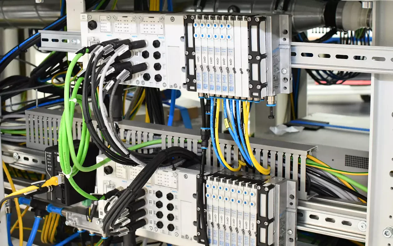
The port layout assigns a unique identifier, function, corresponding connector, and cable product number to each connector. Power connections, standard I/O ports, safety I/O ports, Ethernet ports, and fiber optic lines must be visually distinguished from one another; connectors of the same type should be identified through coding or layout arrangements to prevent incorrect connections. The diagram shows both ends of a cable assembly, the shield and PE ground connections, any exposed conductors, and the panel terminals, ensuring that both laboratory tests and field installations are based on the same accurate information.
If machine modules can be connected and subjected to functional testing before shipment, the value of the system’s cabling is significantly enhanced. During on-site acceptance, mechanical locks, cable damage, and labels are first inspected; subsequently, tests are conducted to verify the protective earth continuity, pin alignment, insulation quality, and functional performance. For data lines, it may be necessary to obtain a channel test report using appropriate certification equipment. The testing methods, acceptance criteria, and recording formats must be specified in the project’s quality plan.
Moving to customisation when a standard product is insufficient
If the standard portfolio contains the appropriate interface options, and the only variation lies in the length, configuring the system cable may be sufficient. However, if the combination of different device connectors is required, special pinning arrangements, custom cables, multiple branching configurations, special protective tubing, panel mounting, or additional testing is needed, HARTING Customised Solutions should be considered. The decision regarding whether to use a custom solution should be made at the beginning of the project; making unauthorized modifications on-site after the standard product has been ordered may render the data sheet and approval process invalid.
In custom solutions, maintaining standard interfaces as much as possible brings advantages in terms of maintenance and supply. Only the necessary components are customized; any changes are documented in the drawings, product structure diagrams, labels, and test plans. Factors such as producibility, minimum order quantity, sample preparation time, and mass production schedules cannot be assumed based on the technical specifications alone; they must be clarified during the detailed bidding process with HARTING and the project stakeholders.
Information required for quotations and orders
- The full model numbers of the two devices to be connected, the interface diagrams, and the current pin assignments.
- For each type of terminal, the connector series, coding, gender, number of contacts, orientation, and locking mechanism are specified.
- Power circuits: voltage, continuous and peak current, protective earth, and disconnection under load
- Signal circuits: channel type, common potentials, shielding, and permissible voltage drop
- In data lines, there are concepts such as protocol, physical layer, speed, category, shielding, and channel topology.
- Cable length, tolerances, fixed or movable routing, bending, and torsion profiles.
- Requirements for the sheath with regard to temperature, oil, chemicals, UV radiation, fire resistance, and industry-specific standards.
- IP target, counterpart device, unused port covers, and cleaning methods.
- Pre-connected connections at one or both ends, for on-site installation or as a customized solution.
- Labeling, packaging, test report generation, and requests for spare parts and revision management.
With this information, HARTING system cabling goes beyond being merely a product for purchasing cables; it becomes a common interface for machine modularity, laboratory testing, field installation, and maintenance strategies. Oskon prioritizes standard system cables and can match power, signal, and data lines according to actual application conditions. When standard options are insufficient, it can manage customized solutions in a separate and traceable manner.