Manage air preparation, cooling water and booth requirements together in paint shop climate control. Match temperature and humidity control to production recipes, measurement locations and utility capacity.
Clarify the terminology used in the project
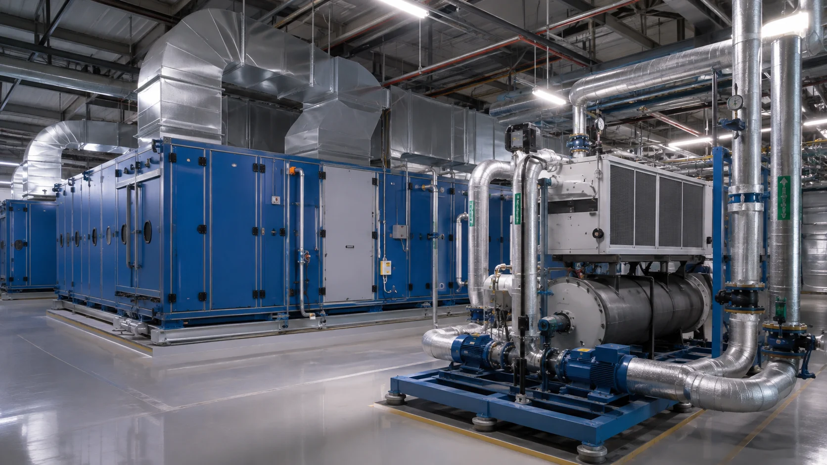
The scope of air preparation or climate control equipment referred to as TAR can vary by plant and supplier. Specifications should explicitly list fans, filters, heating, cooling and humidity control rather than relying on the abbreviation. Treat the chiller as part of the relevant cooling circuit. Assess booth demand and utility capacity against the same load scenarios.
The control point must be correctly located
Supply air temperature, as well as measurements within the booth and the return air duct, help answer various questions. The fact that the target temperature is reached at one point does not necessarily mean that the entire application area meets the requirements. The locations of the sensors are selected with consideration given to air distribution, maintenance accessibility, and the possibility for calibration. During commissioning, on-site measurements are taken to verify their representativeness. The maintenance requirements associated with humidity measurements are also an integral part of the planning process.
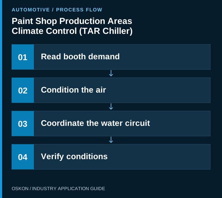
Coordinate the air and water circuits
Monitor cooling demand, valve position, water temperatures and circuit flow together. A chiller-running signal does not demonstrate sufficient cooling at the coil. Pump, valve and measurement feedback help distinguish faults. Establish control that prevents unnecessary simultaneous heating and cooling, in line with equipment design and process requirements.
Define production and standby modes
The mode used outside production hours takes account of the time needed to make the booth ready again and the material conditions. Changes intended to reduce energy use must be verified for their effect on application quality. The operator interface clearly distinguishes standby mode from production-ready status. At the start of a shift, a time schedule alone must not grant production permission before the required conditions are met.
Use trends to investigate deviations
Temperature or humidity fluctuations may be associated with load changes, sensor problems, valve behaviour, filter condition or utility capacity. Recording the setpoint, measurement and control output together helps investigation. Alarm limits and delays are determined by process requirements. Investigate the conditions that trigger recurring warnings rather than simply silencing them.
Acceptance testing must cover different loads
Define acceptance testing for low and high production loads, seasonal design conditions and recovery after stoppages. If every season cannot be observed during commissioning, clearly record the conditions to be verified later. Interpret energy indicators alongside production and outdoor conditions. This avoids misleading conclusions based on directly comparing total consumption on different days.
Key information to monitor in the automation system
| Control point | Monitored information |
|---|---|
| Air condition | Temperature and humidity at representative points |
| Cooling circuit | Water temperatures, flow and equipment feedback |
| Operating mode | Production, standby and readiness status |
Three questions to ask at the start of the project
- Is every item of equipment within the TAR scope individually defined?
- Have the measurement points been verified on site?
- Has the return from standby been tested for its effect on quality?
Explore related applications
Explore related processes in Sanding Booths and Body Filler Booths. Browse all Automotive articles or visit Automotive solutions.