






Variable working conditions
During automatic operation, adjustment, cleaning, troubleshooting and maintenance, people approach different hazardous areas.
We handle machine safety with a life cycle approach, from risk assessment to PLr/SIL determination, safety PLC, protective interlocking, safe movement and validation.
Explore the solution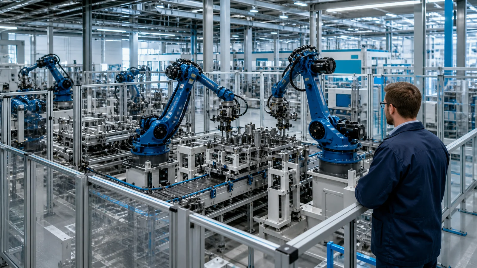
During automatic operation, adjustment, cleaning, troubleshooting and maintenance, people approach different hazardous areas.
A single sensor, contactor or software fault may cause the safety function to fail at the time of request.
Line revision, speed increase or new operating mode; It may override existing risk assessment and security functions.
Machine safety; It begins with identifying hazards, estimating the risk, and mitigating it primarily through design. Protectors, safety devices and safety-related control functions are designed together for remaining risks.
ISO 13849 and IEC 62061 approach; It combines risk assessment, requirement, design, implementation and validation steps in the same safety goal.
Machine limits, usage patterns and exposure scenarios is determined.
→The required performance is defined for each security function.
→Sensor, safety PLC, driver and end elements are integrated.
→It is proven that the requirements are met through calculations, analysis and tests.
Each function; It is handled independently, taking into account the way the machine is used, the severity of danger, exposure and the possibility of avoidance.
Machine limits, life stages, tasks, hazards and risk reduction measures are documented.
Safe situation, reaction duration, operating mode, reset and restart conditions are defined.
Safety inputs/outputs, safety communication and zone architecture are designed with error behaviors.
Functions such as STO, SS1, SLS and safe direction are designed to be implemented. It is selected and parameterized according to the risk.
Category/architecture is calculated to meet the target performance with MTTFd, DC, CCF or PFHd data.
Normal operation, sensor error, energy loss, reset and reboot scenarios are tested against acceptance criteria.
In machinery safety, the safety-related control system alone is not the solution; structural design, protective measures and usage information are part of the same risk mitigation strategy.
Usage scenarios covering the product, operator, maintenance and all operating modes are drawn up.
Analyze danger, exposure, possible harm and possibility of avoidance.
Safe state, input, logic, output, response time and PLr/SIL target are written.
Sensor, safety PLC, driver and actuator architecture. is applied.
Performance calculation and function and error scenario tests are completed.
Revision, maintenance and bypass operations are continued with controlled records.
Door locking, area scanning, safe speed and maintenance mode scenarios.
Two-hand control, light curtain, mold zone and transfer safety.
Emergency stop zones, pinch points, access and safe restart.
Application specific risk reduction in cutting, wrapping, packaging and moving equipment.
Customer and facility information has been anonymized to meet confidentiality obligations.
 ANONYMOUS PROJECT
Fragmented control practices were unified through a standard PLC/HMI architecture, controlled operating modes and verifiable safety functions.
Read the story → ANONYMOUS PROJECT
Heavy-load movements were converted into a safe, traceable crane operation driven by production priorities and stock data.
Read the story →Share the machine or process boundary so the relevant safety engineering team can assess the next step.
Request a safety scope review Your request is routed directly to the relevant engineering team.
Engineering confidence with Oskon.
Leave your details and our expert engineers will contact you for a preliminary consultation tailored to your needs.