The fact that an industrial cable has the correct electrical cross-section does not necessarily guarantee its reliable operation in a moving machine. Repeated bending in the cable carriers, torsion, acceleration, and deceleration in the robotic arm, contact with lubricants, wear, and electromagnetic interference all have a combined effect on the conductor, core wires, shielding, and outer sheath of the cable. Therefore, when selecting a motion control cable, it is essential to first determine the type of motion, the operating environment, the signal transmission requirements, and the expected service conditions, rather than simply focusing on questions such as “how many core wires?” or “what is the cross-sectional area?”
Birtas Kablo’s product portfolio is divided into categories such as industrial flexible cables, energy-chain cables, cranes and drums, as well as cables for robotic motion. In the field of control cables, subcategories include PVC, PUR, HFFR, TPE, cables for servo motors, encoders, and robotic applications. Although these categories are related to each other, they are not synonymous. For example, a flexible control cable designed for fixed cable-tray installation is not automatically suitable for continuous cable carriers applications; similarly, a cable suitable for a cable carriers cannot be used in a robotic axis without first verifying its compatibility with the axis’ torsion profile.
Distinguish flexibility from continuous-motion endurance
The term “flexible cable” often refers to cables that are easy to install or have fine-stranded conductors. Cables designed for continuous motion are specifically engineered to withstand repeated mechanical stresses within specified bending radii, speeds, accelerations, and movement paths. When evaluating their suitability, it is not sufficient to consider only the class of the conductors; factors such as the lay length of the conductors, the layer arrangement, the separators, the mobility of the shielding, and the compatibility between the inner and outer sheaths are also essential. If a cable is labeled as “highly flexible” in a catalog, this does not guarantee unlimited cycle life if the installation requirements are not met.
For motion profiles, it is necessary to record parameters such as stroke length, cycle frequency, daily operating time, maximum speed and acceleration, whether the cable rotates around its own axis, and whether any tensile forces are generated. In the context of cable systems, factors such as weight, the degree of chain filling, and friction between cables also need to be taken into account. For freely hanging connections, oscillation, tension, and the load transmitted to the connection point are critical factors. If these details are not specified in the technical specifications, it is not possible to properly compare different cables with the same conductor cross-section.
| Operating mode | Main mechanical stress | Critical selection check |
|---|---|---|
| Fixed tray or channel | During installation, individual bends may occur, as well as effects from the surrounding environment. | Fixed bending radius, sheath, and installation environment |
| Free and intermittent movement | Bending, oscillation, limited tensile strength. | Temperature and bend radius for dynamic use; load at the connection point |
| cable carriers | Repetitive directional bending, speed, acceleration, and friction. | Definition of dynamic usage, chain geometry, and cable layout. |
| Robot axis | In addition to bending, it also allows for torsion and multi-axis movement. | Permitted degrees per meter, cable length, and robot program |
| Drum or crane | Twisting, pulling, stretching – and often in outdoor environments. | Diameter of the drum, tensile strength, winding arrangement, and vertical load. |
Selecting control cables for moving cable carriers
In an cable carriers, the cables are arranged in such a way that they follow the neutral axis of the chain and are bent in a regular pattern within a specified radius. If the chain is filled too tightly, the cables may press against each other; whereas the unintentional overlapping of cables of different diameters can lead to friction and torsion. At both ends, the cables must be secured in a manner that complies with the manufacturer’s specifications and the chain’s design. In the moving sections of the chain, the cables should not be subjected to tensile forces. For horizontal applications with long strokes, additional support and guiding structures are also necessary.
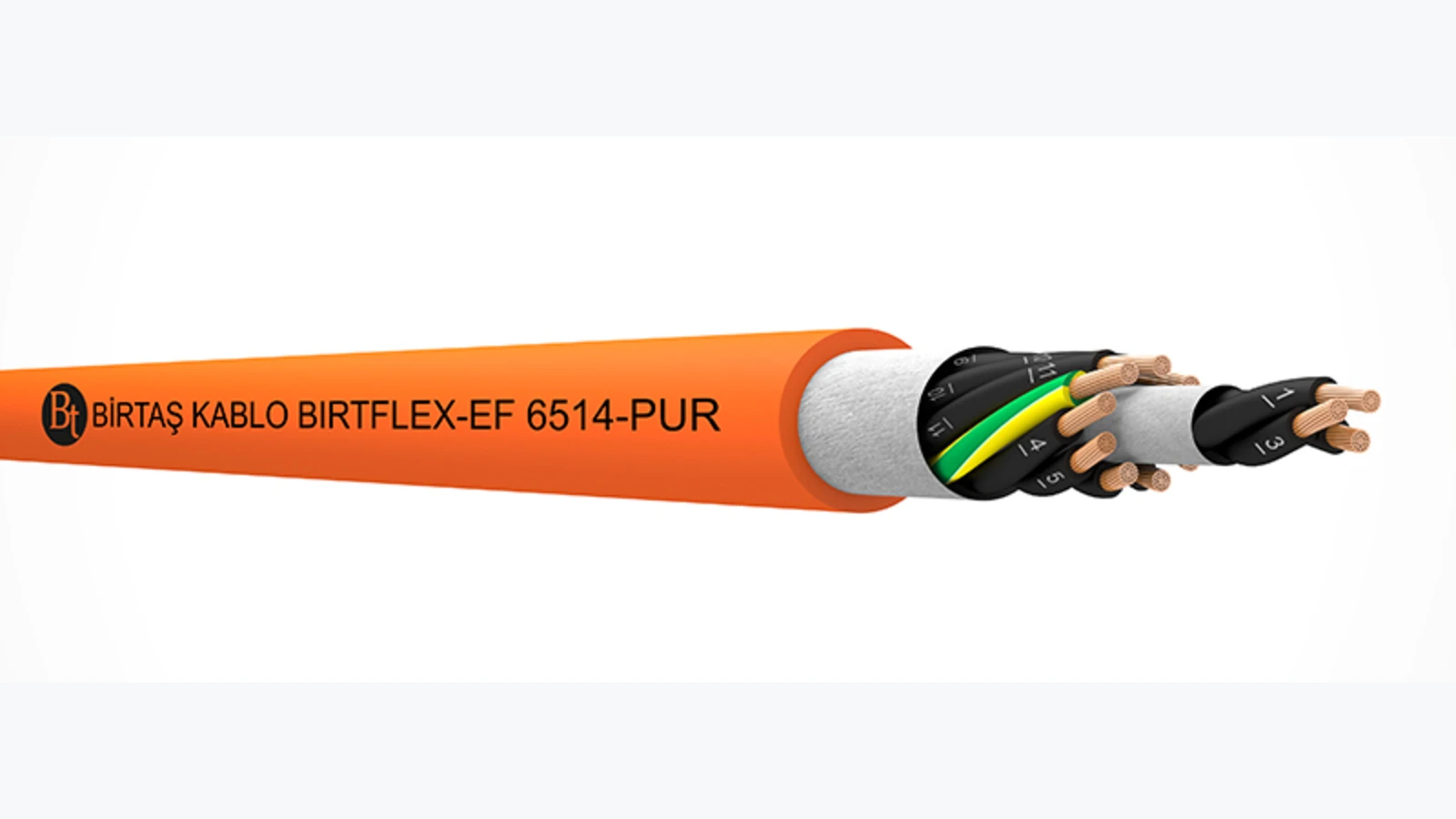
Birtaş Kablo’s BIRTFLEX-EF 6514-PUR product is described on the official website as a highly flexible control cable with a PUR sheath and TPE insulation. The conductor material meets EN 60228 Class 6 standards, and the specified voltage rating is 300/500 V. The product data sheet indicates that the optimal operating temperature range is −50 to +90 °C for stationary applications and −15 to +80 °C for mobile applications. The minimum bending radius is specified as 4 × D for stationary applications and 7.5 × D for mobile applications. These parameters serve merely as design criteria for this particular product line; the actual radius of the cable assembly, as well as the selected cross-sectional dimension, must be verified accordingly.
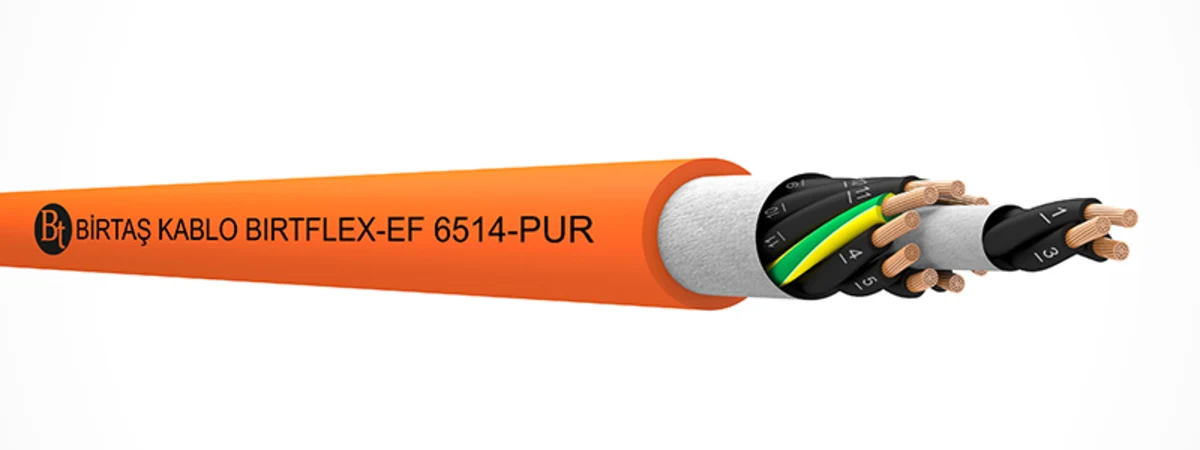
The choice of a PUR sheath alone does not eliminate all chemical and mechanical risks. The manufacturer specifies the product’s resistance to tearing, wear, indentation, adverse weather conditions, cold, oil, various chemicals, hydrolysis, microorganisms, ozone, and UV radiation; however, the specific chemical substance present in the field, its concentration, temperature, and duration of exposure must still be confirmed. The flame-retardant properties of the product also depend on the options selected and the markings provided. The term “PUR” does not imply that all variants of this material have the same fire resistance characteristics or chemical compatibility.
Shielding and low-capacitance choices for control signals
Control circuits such as contactors, brakes, valves, and general-purpose digital I/O devices, as well as low-level analog signals, do not share the same electromagnetic sensitivity. For control signals transmitted in the vicinity of high-current power lines or rapidly switching loads, route separation, shielding, and equipotential bonding must be carefully designed. The selection of a shielded cable alone cannot compensate for improperly terminated shielding or a lack of power-signal separation.
On the official product page, BIRTFLEX-EF 659-C-PUR is described as a highly flexible control cable with a PUR sheath and a shielded design, featuring PP insulation. It is explicitly specified that the tin-plated copper wire mesh shield provides protection against external electrical interference. The product is designed for low-capacitance applications in dynamic industrial environments. This family of products is used in various fields, including cable carriers, conveyor and production lines, assembly lines, and robotic applications. The exact number of conductors, cross-section, outer diameter, voltage rating, temperature range, and bending specifications must be selected according to the product code specified in the order.
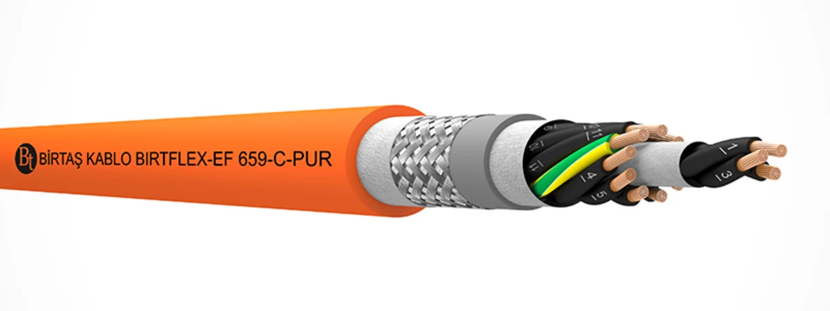
In the connection of shielding wires, the goal is to provide a low-impedance, controlled path for parasitic currents. Connecting the stranded wires with a long, thin tail can reduce the shielding effectiveness at high frequencies; therefore, it is preferable to use appropriate cable glands or 360-degree shielding clips. The decision regarding whether to connect both ends, one end only, or to implement functional grounding should be based on factors such as the type of signal, frequency, and the equipotential structure of the installation. The functions of the protective conductor and the signal shielding should not be confused.
Robotic motion requires a separate cable class
In a six-axis robotic arm, the cable does not simply bend back and forth in the same plane; instead, it changes direction along different axes and twists along its own length. Birtaş Kablo’s definition of robotic motion includes continuous bending, high-speed axis movements, and a torsional capacity of up to ±180 degrees per meter. However, this upper limit should not be used automatically for every product and every application; the specific torsional requirements, test lengths, and motion parameters must be verified for the selected product.
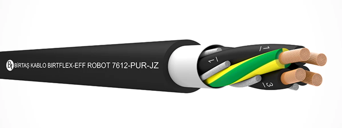
The BIRTFLEX-EFF ROBOT 7612-PUR-JZ is an example of a control cable with TPE insulation and an exceptionally flexible PUR sheath. According to the official specifications, it is designed for use in robotic applications involving mechanical stress, pulling, bending, and torsion, as well as in cable systems in various fields. The manufacturer describes the conductor composition as consisting of wires finer than those specified in EN 60228 Class 6, roughly corresponding to Class 7. It is also noted that the cores are laid up at a suitable pitch with filler elements within the sheath, and PTFE separators are used. This technical design determines the product’s performance; its actual service life is determined by the robot’s operating parameters and the quality of its manufacturing and installation.
Interpreting PVC, PUR, HFFR and TPE correctly
Material abbreviations should be read in conjunction with the layer in which they are used within the cable. The conductor insulation may be made of PP or TPE, the inner sheath may consist of a different compound, while the outer sheath can be PVC or PUR. PVC control cables offer a cost-effective option for industrial applications requiring fixed or limited movement, when used with the right products and installation methods. PUR outer sheaths are particularly suitable for applications involving heavy wear, exposure to oils, or harsh environmental conditions. The term “HFFR” is related to the requirements regarding the behavior of halogen gases and smoke during a fire; it does not in itself determine the suitability of a cable for mechanical applications.
A cable can be simultaneously “halogen-free,” “flame-retardant,” “oil-resistant,” and “flexible,” but each of these properties is based on separate testing standards and defined conditions. Technical documentation should not only include marketing claims but also the relevant test standards, product specifications, and, where necessary, quality certification. If the application involves specific fire safety requirements, such as those in hospitals, tunnels, public transportation systems, or escape areas, the CPR classification and relevant project regulations must also be carefully considered.
Separate power, control, servo, encoder and data connections
In the same machine chain, components such as motor power cables, brake lines, thermistors, encoder feedback signals, safety circuits, and Ethernet cables may be present. The voltage, current, frequency, and parasitic sensitivity of these circuits vary. Combining incompatible functions into a single cable in order to reduce the number of wires can pose risks regarding insulation coordination, EMC compliance, and maintenance. When using hybrid or servo cables, it is essential to verify the configuration of power conductors and control pairs, the shield arrangement, and the connection requirements specified by the drive manufacturer for each particular product.
The calculation of the cross-sectional area depends not only on the continuous current flowing through the cable. Other factors that need to be considered include the length of the line, voltage drop, initial current, ambient temperature, the presence of multiple cables in the same run, and the thermal effects associated with dynamic applications. For control and analog signals, parameters such as loop resistance, capacitance, and shielding are important; for encoder or data communication lines, impedance, pair twist, and the target communication protocol also play a crucial role. If a manufacturer classifies a cable as a “control cable,” it is not appropriate to convert it into an Ethernet or servo feedback line simply because it is equipped with a certain type of connector.
Installation rules for cable carriers
- Use the actual outer diameter. The minimum bending radius should be calculated based on the outer diameter of the selected product code, rather than the nominal product family designation.
- Lay the cable without twisting it: Unwind the cable without rotating it around its axis; do not pull the ring sideways to avoid creating torsion.
- Leave space: Provide a space in the chain where the cables can move freely without overlapping each other.
- Manage their diameters: Arrange large power cables and small signal cables using suitable dividers.
- Cut off the tensile load: Do not keep the cable taut in the moving section; determine the fixing points in accordance with the practices of the chain and cable manufacturers.
- Test the route: In short, observe the loads of compression, friction, bending, and connection at the shortest, longest, and intermediate positions.
Commissioning and maintenance plan
During the acceptance test, cable labels, product codes, and reel information are compared with the project specifications. The insulation, continuity of the conductors, as well as the protective-earth connections and the shielding are verified using appropriate testing methods. The machine is first operated at a low speed and then gradually increased to its normal operating speed; the movement of the cables relative to each other and the connection points are closely monitored. In the case of robotic applications, all programmed positions, as well as emergency stop and restart functions, are evaluated. The testing voltage generated by the measuring device must be selected in such a way as not to damage any associated electronic components.
During periodic maintenance, it is necessary to check for signs of glazing, flattening, breaks, or cracks on the outer sheath; chips and dirt inside the energy chain; loose connections at the fixing points; and any tensile stress on the connectors. Splicing only the damaged section within the moving area can compromise bending behavior and sealing integrity. The replacement cable must match the original product code and operate under the same conditions. The root cause of the fault must be addressed before simply replacing the cable.
Technical data to prepare for a quotation
- Cable function, voltage, current, core count, cross-section, signal, or protocol
- Fixed, free, cable carrier, robotics, festoon, or drum-type motion classes.
- Stroke, cycle, speed, acceleration, torque, tensile load, and current bending radius.
- Internal and external environments; minimum and maximum temperatures; details regarding exposure to oil and chemicals.
- UV rays, ozone, water, wear and tear, sparks, welding slag, and requirements regarding fire behavior.
- Shield, protective earth (PE), core identification, sheath color, connectors, and termination method
- Energy-chain internal dimensions, fill, dividers, existing cables, and three-dimensional routing
- Required standards, certifications, test reports, length, tolerances, and the quantity of spare parts.
Oskon’s approach to product selection considers the cable not as a consumable separate from the machine, but rather as an integral component of motion, electrical functionality, and environmental conditions. After identifying the appropriate candidate from the Birtaş Kablo product range, the full product code, the latest technical specifications, and installation requirements are all verified. This approach aims to create a cable solution that is practical, maintainable, and capable of meeting real-world application needs, rather than simply selecting the option with the highest specifications in a catalog.
Official technical resources
- Birtaş Kablo – Industrial Flexible Cables
- Birtaş Kablo – Energy-Chain Cables
- Birtaş Kablo – Control Cables
- Birtaş Kablo – BIRTFLEX-EF 6514-PUR
- Birtaş Kablo – BIRTFLEX-EF 659-C-PUR
- Birtaş Kablo – BIRTFLEX-EFF ROBOT 7612-PUR-JZ
The published specifications depend on the product family and variant. Before placing an order, it is necessary to confirm with the manufacturer the exact product code, as well as the current data sheet, operating conditions, standards, certifications, and availability of the product.