A handling system is far more than just a set of axes that move a component from point A to point B. The moving mass, the working area, the cycle time, the gripper, the cable carrier, the motor, the drive, the control system, and the machine frame are all components of the same performance chain. Festo’s current range of Cartesian systems offers ready-to-assemble platforms, ranging from single-axis movements to two-dimensional linear gantry solutions and three-dimensional gantry structures. This guide is designed to help you select the right kinematic configuration, accurately define the system’s limitations, and ensure that the acceptance tests can be conducted even in the early stages of the proposal process.
Define the motion task before selecting the robot type
Starting selection with a product name often creates unnecessary complexity. First define the part’s start and end positions, intermediate waypoints, orientation and prohibited volumes. If one-directional transfer is sufficient, extra axes increase cost, moving mass and maintenance. Consider a two-axis linear gantry for pick-and-place in a vertical plane, or a three-dimensional gantry for access to different horizontal X-Y positions and heights.
The axes of Cartesian systems are directly correlated with the machine’s coordinate system. This feature can simplify programming and the prediction of the working area. However, for tasks that require the part to continuously change direction, navigate around obstacles by following curved paths, or access multiple stations at different angles, additional rotary axes or other robotic kinematic configurations may be necessary. The right solution lies not in increasing the number of axes, but in accurately defining the degree of freedom of the movement.
Different tasks for 1D, 2D and 3D architectures
| Architecture | Main motion | Typical task | Critical selection consideration |
|---|---|---|---|
| Single-axis system | Positioning in one direction | Inter-station transfer, pushing and pulling, indexing | Stroke, direction of movement, moving mass, and assembly stiffness. |
| Linear gantry | Two dimensions in the vertical working plane. | Picking from conveyors, feeding machines, and sorting. | Dynamic alignment of the horizontal and vertical axes |
| Three-dimensional gantry | Volume motion in the X, Y, and Z directions | Palletizing, tray loading, multi-station feeding systems | Cross-beam geometry, synchronization, bending capacity, and access volume. |
The categories listed in the table represent different starting points. If a gripper possesses its own axis of rotation or inclination, the total degree of freedom is also specified. Monitoring the movement of a conveyor requires different control mechanisms compared to moving it to fixed positions. Similarly, using image processing to pick up random parts necessitates calibrating the camera coordinates with the robot’s coordinates. These additional functions of the process must be taken into account when selecting a handling system.
YXCS: a single axis as a pre-engineered system
YXCS is a single-axis system configured for long one-dimensional movements. Festo describes it as ready to install, including an cable carriers and a suitable motor/servo-drive package. Current technical documentation lists a family maximum working stroke of 3000 mm; verify the usable stroke against the selected axis size, dynamic profile and configuration. The system is offered for horizontal mounting.
In single-axis transfers, the primary mistake is failing to take into account the total mass of the product being transported. The moving parts—including the slide, adapter, gripper, valve island, sensors, as well as the moving sections of the product and energy transmission chains—all contribute to this total mass. If the center of gravity of the load is located away from the surface of the slide, both the force and the moment capacity must be considered accordingly. In cases involving long strokes, the bending and vibration of the machine frame can be even more significant than the accuracy of the axis itself.
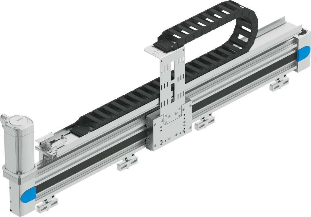
YXCL: two-dimensional motion in a vertical working plane
The YXCL linear gantry combines horizontal and vertical axes in a two-dimensional serial-kinematic handling system. Festo describes scalable Y and Z strokes, pneumatic or electric vertical-axis options, an cable carriers and a suitable motor/servo-drive package. The family includes Y strokes up to 3000 mm; this limit must not be assumed to apply to every load and dynamic combination.
The selection of the vertical axis is not merely a matter of comparing speeds. Various factors must be taken into consideration, including the product’s ability to reach different intermediate heights, its ability to be held in a stopped position during power outages, precise positioning, the number of cycles, and the requirements for the compressed air infrastructure. A pneumatic Z-axis may be suitable for fast movements at specific end positions, while an electric Z-axis can offer the advantages of multiple intermediate positions and programmable motion profiles. The final decision should be based on the configuration options available in the Handling Guide Online and the latest technical documentation.
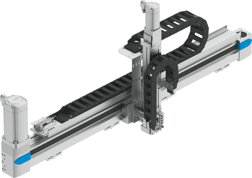
YXCR: a three-dimensional working volume
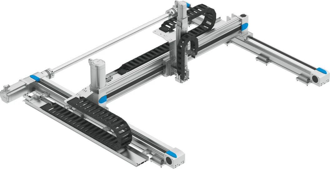
The YXCR series consists of three-dimensional gantry modules that combine multiple axes to enable movement in the X, Y, and Z directions. Festo’s official website highlights its universal applicability, particularly in applications requiring long strokes and high loads; this product family offers configurations with an X-axis range of up to 3000 mm. A technical document dated 2026 details both the YXCR model itself as well as the YXCR-B variants with different mechanical designs and axis combinations. Therefore, the type of gantry, guide rail, or axis configuration should not be determined solely based on the image of the product family.
In a three-dimensional system, the parallelism of the X-axis beams, the mass carried by the Y-axis, and the moment of the Z-axis when extended are all important factors. A long Z-axis stroke can increase the oscillation at the gripper’s operating point. When precise positioning is required after a rapid horizontal movement, it is not only the maximum speed but also the positioning time that matter. The selection of the drive system takes into account factors such as stroke length, load capacity, acceleration, cycle time, operating speed, and the dynamic effects of the cable and hose packages.
How should the workspace be specified?
Robot access is not merely the distance between two points. It also requires specifying the coordinates of the picking and placing positions, the minimum and maximum heights of the product, the approach direction of the tool, as well as any obstacles and the boundaries of conveyors, fixtures, and doors. The volume occupied by the gripper’s body and its power connections must also be taken into account when developing the collision model. Access spaces must be ensured for maintenance purposes, including access to the axis cover, motor connector, and cable chain.
The stroke length should not be increased arbitrarily, as doing so may increase the machine’s size, axis costs, and movement time. Instead, factors such as production tolerances, product variations, tool changes, and adjustment margins should be considered separately. The limitations imposed by software should not be confused with the mechanical stroke length or safety distances. The actual stopping distance after an emergency stop must be verified through risk assessment and measurements.
Break the cycle time down correctly
Total cycle time includes detection, decision, gripping, vacuum or grip confirmation, lifting, horizontal travel, placement, release and return. Treating theoretical robot motion time as the whole cycle is misleading. Simultaneous-axis motion requires a compatible path plan and collision envelope. Acceleration and deceleration can matter more than maximum speed over short distances.
If the load profile includes multiple products, the heaviest product will limit the overall capacity, while the lightest product may affect the stability of the gripping mechanism and adjustment settings. The forward and reverse motion cycles can be evaluated separately. The variable input speed of the production line, as well as its waiting and buffering behaviors, are also taken into account in the simulation. During the acceptance test, in addition to the average cycle time, the worst-case scenario, the percentage distribution of load, and the recovery time after a stop are recorded.
Loads, moments and mechanical stiffness
The “payload” value listed in the catalog should not be used alone without conducting application-specific dynamic calculations. The total mass being transported determines the guiding forces related to acceleration and axis direction. The distance of the gripper from its axis center generates a moment; as the Z-axis length increases, the leverage effect also increases. When multiple axes are accelerated simultaneously, this results in combined load conditions. The configuration tool must be used in conjunction with these input parameters, and the machine frame must also be structurally designed accordingly.
A non-rigid base, non-parallel connection surfaces, or excessively tight mounting can cause stress and wear. For long beams, the accuracy of the support points, the flatness of the surface, and thermal changes must be taken into consideration. During precise positioning, the motor encoder only provides information regarding the position on the drive side; any deformation or clearance at the tool tip is part of the overall process. If necessary, the tool center point should be verified through independent measurements.
Design the gripper and handling system together
A handling system transports parts with the same level of reliability as the gripper itself. The surface of the part, its porosity, the amount of oil present, temperature, tolerances, center of gravity, and the permitted contact area all determine the appropriate gripper to be used. When vacuum is employed, factors such as evacuation time, leakage, hose volume, and vacuum monitoring requirements must also be taken into account. In the case of mechanical grippers, considerations include the geometry of the gripper fingers, gripping force, opening stroke, and the ability to detect the presence of the part.
If the valves and vacuum generator of the gripper are installed on the moving axis, the hose volume may decrease, but the moving mass increases. In the case of a central layout, the mass may decrease, while the response time and the number of lines in the cable carriers may increase. The optimal distribution is determined based on dynamic calculations and ease of maintenance. The method to prevent the part from falling during an energy interruption is not assessed solely based on the normal gripping force.
Motor, drive and control architecture
Festo handling systems can be configured with appropriate motor and servo drive packages. The advantage of this approach lies in the integrated consideration of mechanical axis characteristics, motor inertia, as well as cable and drive parameters. However, factors such as grid voltage, regenerative energy, braking resistance, control panel temperature, field network connectivity, and safety functions must still be verified specifically for each project. In the event of using third-party motors, it is essential to carefully assess the required adaptations, inertia considerations, couplings, feedback mechanisms, and warranty coverage.
The interaction between PLC control and robot operation must cover various scenarios, including automatic, manual, reference-based modes, as well as situations where the robot is moving, has reached its target, or is in an error state. The recipe data must be properly constrained to prevent movements in invalid coordinate ranges. During restarts, the status of the parts and axes must be verified. If image processing or conveyor tracking is utilized, time synchronization, trigger delays, and coordinate conversion processes must also be included in the acceptance testing.
Cable carriers and field connections
The presence of a cable carrier in a ready-made system does not necessarily mean that any additional cables or hoses added will automatically fit properly. It is essential to check the degree of filling, the minimum bending radius, the suitability for mobile applications, as well as the presence of separation devices and fixing points. Power cables, encoders, sensors, and pneumatic lines must be installed in accordance with the manufacturer’s specifications. No pulling force should be exerted on the cables at the outlet of the cable carrier; the length of the cables must be set so that they neither retract nor accumulate throughout the entire stroke.
In three-dimensional movements, the lines transmitted by a chain can be transferred to a second moving chain. The bending and torsional properties at the transition points are particularly important to consider. Compression of vacuum and pneumatic lines not only reduces their flow rate but can also affect the reliability of their gripping capabilities. During regular inspections, components such as chain links, separators, cable sheaths, hose friction, and connector fixations are thoroughly checked.
Configuration with Handling Guide Online
On its latest handling product pages, Festo places the “Handling Guide Online” tool at the heart of the system design and ordering process. This tool assists in selecting the most suitable combination of axis, motor, and drive component based on parameters such as kinematics, working space, load, and dynamic conditions. CAD data as well as configuration-specific information can be integrated into this process. It should be noted that this tool does not correct any incorrect or missing input data; the resulting system configuration is merely as accurate as the information provided by the user.
The configuration details, including version and date, must be stored within the project file. Any subsequent changes to parameters such as the weight of the holder, the stroke length, the cycle time, or the mounting direction require recalculation. The configuration used in the quotation must match the configuration specified in the order and actually implemented in the final product. Accessories, sensors, cables, and mounting components are also tracked within the product structure.
Safety design and protective arrangements
Cartesian kinematics do not inherently make a robot safe. Assess mass, speed, crushing points, falling loads and accessible areas. Design protective fencing, guard interlocks, light curtains, safe speed or Safe Torque Off functions to the required performance level. Measure stopping time to verify protective-device separation distance. Also secure the vertical axis and carried part against the effects of power loss.
The reduced speed, the requirement to operate by holding the button down, as well as the need for a visual line of sight and local control mechanisms must all be determined based on the specific requirements of the facility. Relying solely on software-based stop mechanisms is not sufficient for maintenance access; it is essential to ensure energy isolation and the safe dissipation of any stored energy. The re-powering procedure must include a safe rescue mechanism in case the axis reference is lost.
Values to measure during acceptance testing
- The actual cycle time for picking up and placing the lightest, nominal, and heaviest products respectively.
- Positioning accuracy, repeatability, and settling time at the tool center
- The movement of the cable and hose throughout the entire cycle, as well as the accompanying noises and friction generated by the cable carrier.
- Frame vibration, long-beam deflection and mechanical behavior in different movement directions
- Grip verification, scenarios for missing parts, double parts, and loss of grip.
- Stoppage in case of door opening, emergency, power failure, or communication error.
- Reference, recipe modification, manual recovery, and restart procedures.
- Temperature, error records, and cycle distribution during the shift period.
Maintenance and spare parts plan
During periodic inspections, the belt or shaft drive, the condition of the lubrication system, the connecting bolts, the reference sensors, the motor cables, and the cable carrier are all checked. Noise levels, motor current, tracking errors, and trends in cycle times can serve as early indicators of mechanical wear. When issues are detected, the root causes—such as mechanical clearance, friction, misalignment, or load variations—are investigated, rather than simply increasing control settings arbitrarily.
In the spare parts list, general descriptions such as “X-axis motor” are not used; instead, the exact product number, gear ratio, braking system, encoder, cable details, and configuration settings are recorded. drive parameters, robot programs, coordinate conversion data, and safety verification reports are also backed up. The product’s lifecycle is verified on the official Festo website before placing an order; components listed in older brochures are not considered as part of the current product range.
Project data required for a quotation
- The X-Y-Z coordinates of the stations, the height of the products, and the required approach distances.
- Total moving mass, including product, gripper, adapter, valves and moving services
- Center of gravity, external forces, moments, and the orientation of the gripper
- Sequence of movements, simultaneous axes, target cycle time, waiting periods, and operating efficiency.
- Position tolerance, repeatability, settling time, and process measurement methods.
- Frame mounting surfaces, permissible deflection, vibration and environmental conditions
- Gripper type, part detection, vacuum or pneumatic consumption and drop prevention
- PLC, field network, panel power supply, safety functions, and user interface
- List of cables and hoses to be included in the cable tray, as well as maintenance access routes.
- Delivery time, product variety, training, documentation, and the scope of spare parts available.
A good handling system is not necessarily the one with the most axes or the highest catalog speed, but rather the one that completes the process requirements in the simplest and most reliable manner. YXCS is suitable for one-dimensional tasks, YXCL for two-dimensional tasks in the vertical plane, and YXCR for three-dimensional tasks. Oskon evaluates these platforms in conjunction with the application area, the actual moving load, the gripper, the frame, as well as control and safety data; the final configuration is then confirmed using the latest Festo tools and complete product documentation.
Official Festo resources
- Festo — Handling systems and industrial robots
- Festo — YXCS single-axis system
- Festo — YXCL linear gantry
- Festo — YXCR three-dimensional gantry
- Festo — YXCS Technical Documentation (2025/01)
- Festo — YXCL/YXML Technical Documentation (2026/02)
- Festo — Technical Documentation for YXCR/YXMR (February 2026)