Inductive proximity sensors are used to detect the presence of a metal target without any physical contact. Although the task may seem simple, selecting a reliable sensor cannot be based solely on the body diameter or the detection range specified in the catalog. Other factors must also be taken into consideration, such as the type and size of the target metal, whether the sensor is to be mounted flush or protruding, the presence of nearby metal surfaces, the switching frequency, the electrical output, the connection type, as well as any potential exposure to heat, oils, or cooling fluids. This guide presents the SICK range of inductive sensors not as a mere product list, but rather as a step-by-step guide for making informed decisions during machine design.
Which tasks suit inductive sensing?
An inductive sensor generates a switching signal by detecting the changes in the electromagnetic field caused by a metal target. It operates without the need for any wear-prone components such as mechanical levers, rollers, or contact surfaces found in mechanical limit switches. As a result, it can be utilized in a wide range of applications, including detecting the end position of machine slides, confirming the presence of parts within a fixture, monitoring the transition of gears or cams, detecting metal pallets on handling equipment, determining valve positions, and verifying the correct installation of tools. However, this type of sensor should not be used for directly detecting non-metallic objects or for continuously generating measurement values, as these tasks may require different detection principles or analog outputs.
The information “metal surface” alone does not constitute a sufficient specification. A steel reference target may not produce the same switching distance as an aluminum, brass, or copper target. If the target surface area is smaller than the reference plate specified in the catalog, the available detection distance may decrease. If the target approaches the sensor from the side, the difference between the stop tolerance and the switching points must also be taken into account. Instead of accepting the nominal detection distance as the actual working distance of the machine, the designer should establish a distance budget that takes into account factors such as manufacturing tolerances, temperature variations, and a safety margin for reliable operation.
First choices: housing, mounting and actual operating distance
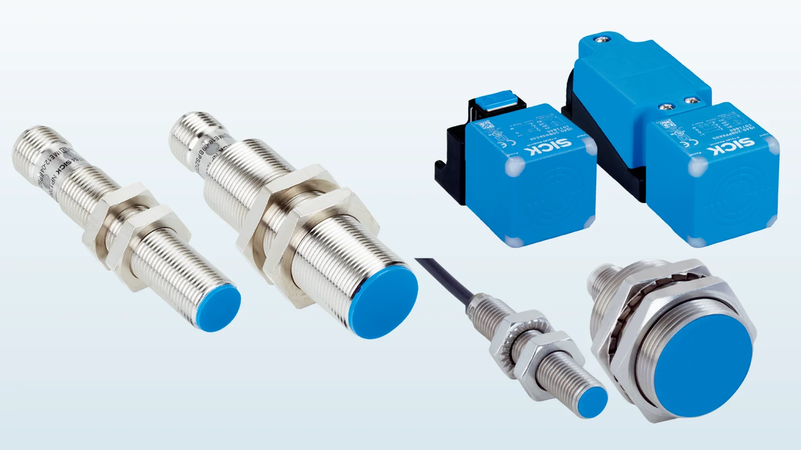
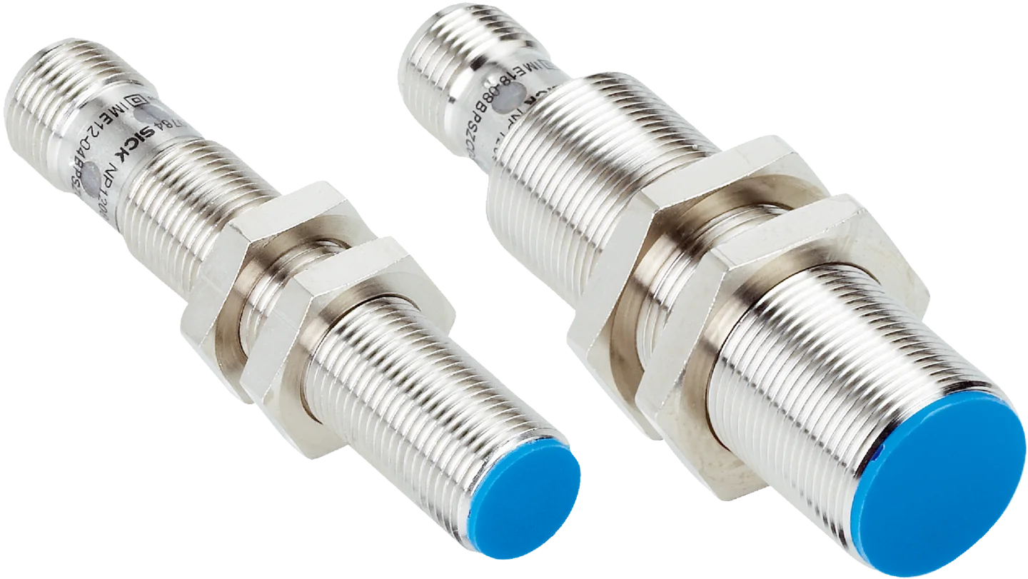
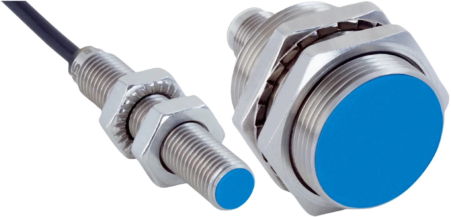
The cylindrical threaded body enables the sensor to be adjusted axially using two nuts and installed in standard holes. Smaller M8-bodied sensors offer advantages in compact mechanisms, while larger bodies can provide a longer detection range or a more robust mechanical mounting, depending on the application. Rectangular-bodied sensors are particularly useful in facilities where a large detection area, different mounting options, or the ability to orient the sensor head in a specific direction are required. When making a choice, it is advisable to consider not only the detection range specified in the catalog but also the rigidity of the mounting fixture, the ease of adjustment, and the possibility of removing the sensor in the event of a malfunction.
For sensors suitable for flush mounting, the active face can be aligned with the metal surrounding in a specific manner to ensure proper functionality. In the case of sensors not designed for flush mounting, additional space is required around the active face to ensure that the detection area remains unobstructed. The mounting distances, the spacing between adjacent sensors, and their relative positioning requirements specified on the product data sheet must be carefully considered during the design process. Failure to comply with these guidelines may allow the metal bracket or adjacent sensors to affect the detection field. Moreover, a longer detection range is not necessarily a better option in all situations – an excessively large detection area may result in the detection of nearby metals or unwanted objects, leading to false signals.
The IME series, as listed on SICK’s current product page, includes models from M8 to M30. These models offer extended detection ranges ranging from 1.5 mm to 38 mm, as well as various electrical options such as DC three-/four-wire and DC two-wire configurations. The same page also specifies that these devices feature IP67 level protection and a temperature range of −25 °C to +75 °C. However, it should be noted that these specifications do not imply that all models within the series share the same mounting format or detection range. After making an initial selection, it is essential to verify the specific detection range, mounting options, connection details, and output circuit configuration of the chosen variant.
Compare product families by application conditions
| Product family | Main scope stated on the official page | Suitable selection scenario | Critical check before quotation |
|---|---|---|---|
| IME | M8–M30; dimensions within the range of 1.5–38 mm; IP67; operating temperature range: −25…+75 °C | Standard machine and factory automation tasks | Flush mounting, target metal, output, and connection of the exact variant |
| IMB | M8–M30; dimensions within the range of 2–20 mm; IP68/IP69K; operating temperature range: −40…+100 °C; body made of stainless steel. | Oil, cooling fluids, outdoor environments, and more extreme operating conditions. | Chemical contact, cleaning method, options for cable/connector, and IO-Link. |
| IQG | 40 × 40 mm; within the family, the range is 20–40 mm; IP68/IP69K; −25…+85 °C | Machines that require a long detection range and flexible rectangular mounting options. | 20-mm or 40-mm versions, mounting direction, distance to surrounding metal, and output options. |
The values in the table are taken from the family summaries on the official product pages of the three families; they should not be interpreted as referring to a single product model. For example, the IME series offers various options in terms of diameter, range, connection types, and switching functions; the IMB series includes different IO-Link and electrical configurations. Specifying “IME, 38 mm” or “IMB, IP69K” in a technical specification is insufficient. Once the exact product code is determined, the data sheet, dimensional drawings, operating instructions, and all relevant certification documents must be stored under the same revision number.
IMB for harsh environments
The IMB series of inductive sensors, developed by SICK, are designed to operate in outdoor environments and in contact with oils, cooling fluids, or lubricants. The current product range includes sensors with M8–M30 housings, detection ranges of 2–20 mm, IP68 and IP69K protection levels, operating temperatures ranging from −40 °C to +100 °C, as well as robust stainless-steel housings and plastic active faces. Additional features include an optical adjustment indicator, self-locking nuts, and the option of IO-Link communication. However, these specifications are only applicable when the correct IMB model is selected and the connection/mounting requirements specified by the manufacturer are followed.
When selecting a sensor for harsh environments, the IP code alone is not sufficient as a decision-making criterion. Factors such as the chemical composition and temperature of the cooling fluid, as well as the direction of its spraying; the likelihood of metal debris accumulating on the sensor; the durability of the cable sheath; whether the connector is properly mated and securely fastened; and the use of cleaning agents and the process of high-pressure cleaning must all be carefully considered. Even if the sensor body is suitable, if the connecting cable or the corresponding socket is not compatible with the environment, the integrity of the entire system cannot be ensured. Moreover, a high temperature rating does not necessarily mean that the cables, connectors, and junction boxes in the vicinity of the sensor also have the same temperature resistance.
IQG for rectangular housings and long sensing distances
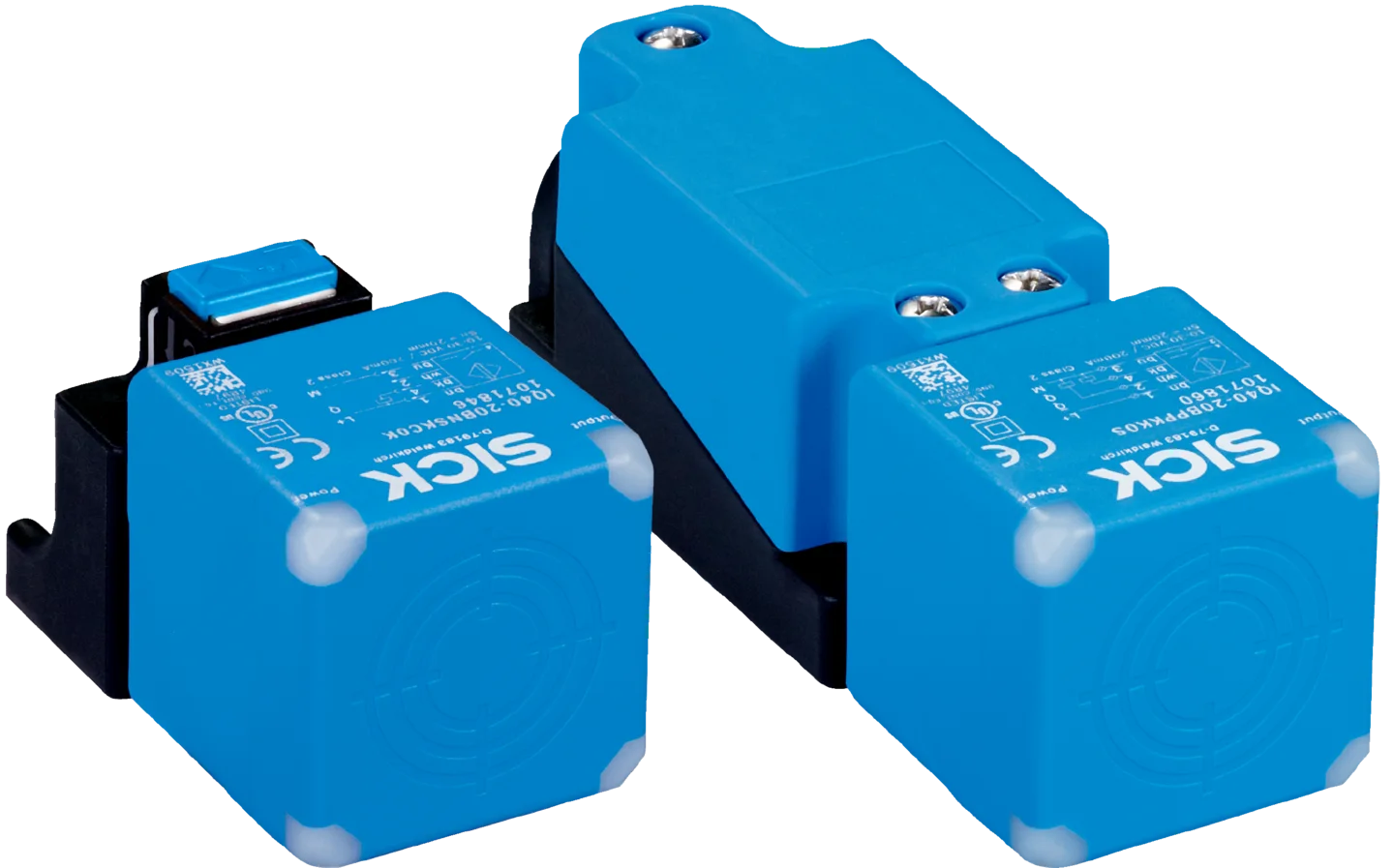
The IQG series features a rectangular body measuring 40 × 40 mm, offering a long detection range and flexible mounting options. The official product page specifies an operating range of 20–40 mm, IP68/IP69K protection levels, and a temperature range of −25 °C to +85 °C. The sensor head can be rotated in five directions, allowing the active face to be adjusted accordingly in machine design. The LEDs located at the four corners also facilitate status monitoring from various angles. The tool-free push-lock mounting system is designed to speed up sensor replacement; however, it is still essential to verify that the mounting components are properly positioned and that the cable is not damaged during installation.
Rectangular sensors are particularly suitable for use on conveyors, transport vehicles, elevator mechanisms, or in the presence of large metal targets. However, the values of 20 mm and 40 mm should not be interpreted as representing a single adjustable range within the same variant; the family includes both flush-mounted and non-flush-mounted options. The actual operating range is determined by the size of the target, the steel structures in the vicinity of the mounting location, and any mechanical vibrations present. On a moving conveyor, the maximum axial misalignment between the sensor and the target must be verified both in the CAD model and, if possible, in a physical prototype.
Electrical outputs and control system connections
The fact that a sensor is mechanically suitable does not necessarily mean that it is also electrically compatible for use with a PLC input. For DC sensors with three or four wires, information such as the PNP/NPN output type, normally open/closed state, operating voltage range, allowable current rating, voltage drop, leakage current, and short-circuit protection features must be obtained from the product’s data sheet. For two-wire sensors, the residual voltage in the closed state and the leakage current in the open state should be considered in conjunction with the threshold values of the connected input module. The color of the wires should not be used as a guide for wiring; instead, the product’s wiring diagram and the connector pin assignment should be followed strictly.
In IMB variants equipped with IO-Link, the sensor can transmit parameter and identification information via communication, in addition to the switching signal. This feature can be utilized for parameter management during product changes, status monitoring, or to incorporate additional process-related information into the control architecture. The presence of IO-Link does not automatically ensure these benefits; the master port type, cycle time, IODD version, process data mapping, PLC function blocks, and the way maintenance personnel will use the data must all be defined within the project scope. Furthermore, for simple applications that only require digital switching, the actual cost-effectiveness of using IO-Link communication must also be carefully evaluated.
Mechanical details that determine switching quality
Since inductive sensors often detect the last few millimeters of a machine’s movement, the rigidity of the bracket becomes critical. If a thin sheet metal connection vibrates, altering the distance between the target and the sensor, even high-quality sensors may produce unreliable signals. It is essential to tighten the screws with the appropriate torque, ensure no pulling occurs at the cable outlet, and use mechanical stops to prevent the target from hitting the sensor. The detection face itself is not a physical stopper; if it is possible to move the sensor during maintenance, methods such as adjustment rods, reference marks, or locked connections should be used instead.
If two sensors are required to monitor the same metal target at close range, the installation guidelines for mutual mounting and side-by-side placement should be obtained from the data sheet. In applications involving rapidly rotating gears or cams, not only the distance but also the switching frequency of the sensors and the duration for which the target remains in front of them are crucial factors. The PLC input filter, network cycle time, and software sampling duration are all taken into account when calculating the total time required to ensure no signal loss. A laboratory test demonstrating the ability to detect a narrow tooth does not guarantee the same results in real-world production environments, where vibrations and tolerances can vary significantly.
Distinguish functional safety from standard detection
The fact that a standard inductive proximity sensor is capable of reliably detecting the presence of a metal object does not in itself make it suitable for use in safety functions. For tasks such as controlling the opening of protective doors or stopping dangerous movements, the appropriate safety sensor, evaluation unit, performance level, and system architecture must be selected based on a thorough risk assessment. In SICK’s product portfolio, inductive products designed for safety purposes are categorized separately. Variants of the standard IME, IMB, or IQG series should not be used as safety components without explicit certification indicating their suitability for such applications.
Information required for quotations and project planning
- Material of the metal to be detected, minimum surface size, thickness, and direction of approach relative to the sensor
- Nominal operating range, mechanical tolerances, vibration, and the risk of sensor-target collision
- Cylindrical or rectangular housing, thread size, flush/non-flush mounting, and bracket drawing
- Supply voltage, PNP/NPN or two-wire configuration, normally open/closed function, and load data
- The choice between a cable or a connector depends on the required length, pin configuration, and the corresponding connecting component.
- Ambient temperature, oil/coolant, water, cleaning processes, dust, external conditions, as well as impact and vibration.
- IO-Link, remote parameter setting, diagnostic functions, or the need for process data.
- Required certifications, whether it involves safety functions, the target quantity, and the approach to spare parts management.
The proposal prepared using this information should not only specify the sensor model but also include details regarding the corresponding cable, mounting accessories, and commissioning requirements. Two products within the same family that may appear similar may actually have different outputs, detection ranges, or connection methods. The product description and the complete order code must be included in the purchase list and must match the device label on the electrical schematic diagram. The settings verified during the trial use of the first machine should be transformed into standardized mounting procedures for mass production.
Commissioning and maintenance checks
During commissioning, the sensor is tested at its farthest and closest tolerance positions. The machine is operated at a low speed to compare the LED signal output with the PLC input status; thereafter, the signal stability is monitored at the actual production speed. If a cable shield is required, the earthing method, the routing of power cables in parallel with the signal cables, and the filters of the input module are checked. In the event of a malfunction, testing the power supply, the counter-target, the looseness of the bracket, the accumulation of metal debris, as well as the PLC input channel separately, rather than replacing the entire sensor immediately, helps to minimize unnecessary component replacements.
The periodic maintenance interval is determined based on the level of contamination and vibration in the application. Common issues include the accumulation of metal particles on the active surface, physical damage to the sensor body, loosening of connection bolts, and cable breaks. Spare sensors should be stocked not only by their model number but also with the same electrical and mechanical specifications. If IO-Link parameters are being used, the backup and automatic reinstallation processes must be thoroughly tested. This ensures that the inductive detection function can be reliably managed as a vital component of the machine, rather than a single component that may be overlooked during installation.