Pneumatic and electrical connection technology serves as the common infrastructure that enables the reliable transfer of air, energy, and information between components within an automation system. Even if the cylinders or valves are properly selected, issues such as narrow hoses, incompatible cable glands, incorrect thread specifications, excessively long cables, incorrect connector coding, or unprotected field connections can still disrupt the cycle time and availability of the system. This guide presents Festo’s range of hoses, automatic connection fittings, and connection cables not as individual products, but rather as a sequence of choices to be followed when designing end-to-end field connections.
Why design the connection as a separate system?
In a pneumatic system, the flow rate is affected at every stage—from the compressor to the preparation unit, from the distributor to the valve, and from the valve to the actuator. As the inner diameter of the hose decreases, the length of the line increases, and the number of elbows increases, the pressure loss can become more significant. The consequences of this include not only a slower cylinder movement but also a reduced force under load, different speeds in both directions, inconsistent vacuum levels, and unnecessarily high supply pressures. Therefore, the connection diameter should not be determined solely based on the port size of the device but should also take into account the required flow rate and the allowable pressure drop.
Even in the electrical aspect, ensuring a physical connection does not guarantee the correct compatibility. The same M12 mechanical format can be used with different coding systems, pin counts, voltage levels, and communication functions. The sensor’s PNP or NPN output, the type of analog or digital signal, the IO-Link connection, the voltage and power requirements of the valve coil, the cable cross-section, and the pin layout of the controller’s input must all be taken into account in the same design. If the pneumatic and electrical systems are not planned together, issues such as maintenance accessibility, the congestion of cable and hose carriers, and the bending radius along the moving axis may arise later on.
Selection sequence: from task to order code
- Define the fluid and the signal. Record air quality, pressure, vacuum levels, or water usage; on the electrical side, record the type of power supply, current, and signal.
- List the connection endpoints: List each device’s thread, tube outside diameter, M8/M12 connector, coding, gender and pin view.
- Determine the dynamics: Distinguish between fixed installations, cable carriers, robot torsion, repetitive oscillations, and situations involving mere assembly during the mounting process.
- Verify the environment: Specify the minimum and maximum temperatures, as well as exposure to oil, chemicals, UV radiation, welding sparks, washing processes, and mechanical impacts in the technical specifications.
- Complete the installation: Manage connectors, hoses, cables, distributors, silencers, labels, and fixing components within the same product hierarchy.
- Check the exact variant: Please confirm the general description on the product family page with the current data page for the product number you wish to order.
Tubing diameter and length in pneumatic lines
When selecting a hose, the outer diameter determines its mechanical compatibility with the fitting, while the inner diameter primarily determines its flow capacity. Two products with the same outer diameter but different wall thicknesses may not have the same inner diameter. In the design process, factors such as the cylinder volume, the desired stroke duration, the number of actuators operating simultaneously, the losses associated with valves and dampers, and the minimum dynamic pressure of the supply line must all be taken into account. A device that functions well in a short, simple laboratory setup may not perform similarly in a longer, more complex mechanical system with multiple connections.
A hose that is excessively large is not always the best option. An increased hose diameter may prolong the filling and emptying times, increase air consumption, and require a larger bending range in the moving mechanism. Therefore, the main distribution line, the valve supply line, and the actuator port can be designed with different diameters. If speed control is to be used, factors such as the direction of flow, the exhaust silencer, and the pushing or pulling nature of the load must also be taken into account. During project approval, the dynamic pressure during the fastest cycle should be measured, rather than the static pressure at the cylinder inlet.
PUN-H tubing: an example of variant verification for standard tasks
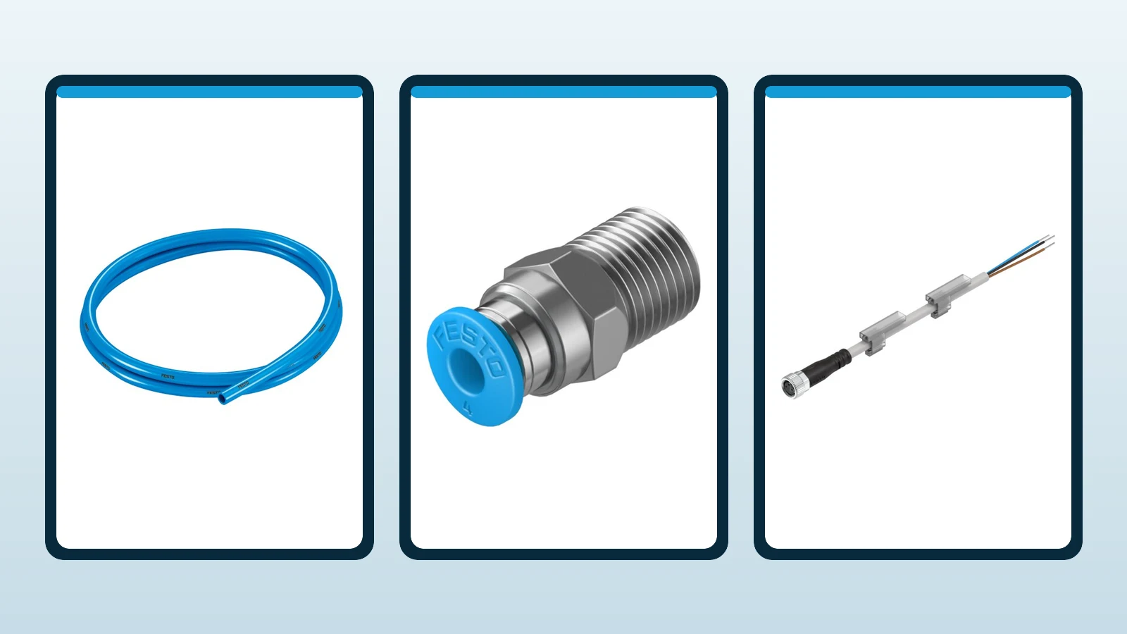
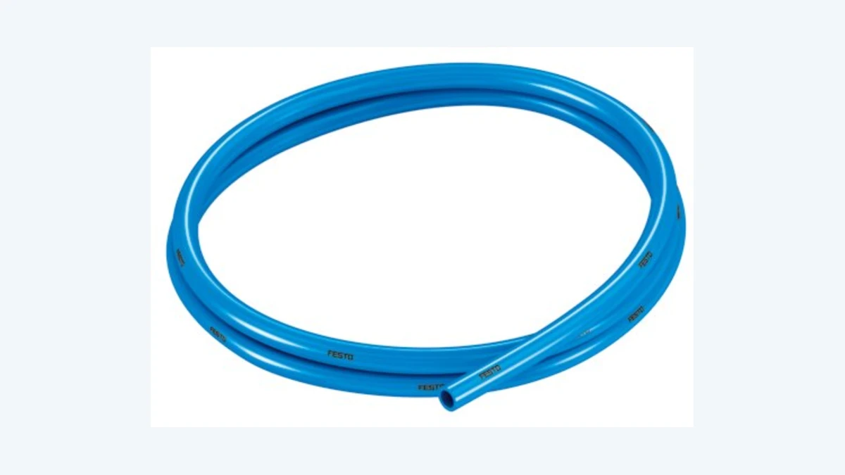
Festo offers a range of pneumatic hoses in various combinations, designed to address environmental challenges such as heat, welding sparks, high pH levels, and hydrolysis, in addition to standard applications. The PUN-H polyurethane hose is one of the available options for a wide range of standard applications; however, the diameter, color, and usage limitations must be determined based on the specific product code. The designation “PUN-H” by itself does not constitute a requirement for specifying pressure, temperature, or bending parameters in the order process.
For example, the August 2026 data sheet for PUN-H-8X1,25-BL, product number 197385, specifies an 8 mm outside diameter and 5.7 mm inside diameter. This variant has a minimum bending radius of 21 mm, a flow-relevant bending radius of 37 mm, an ambient range of −35 to +60 °C and TPE-U(PU) material. It is listed as suitable for cable carriers. Operating pressure across the full temperature range is −0.95 to +6 bar; temperature-dependent operating pressure is −0.95 to +10 bar. These figures apply only to the specified blue 8 mm variant, product number 197385.
On the data sheet, information regarding water use is also provided, but a maximum pressure limit of 0.3 MPa for temperatures ranging from 0 to 60 °C is also specified. This example clearly illustrates that the pressure values stated should not be directly applied to water-based systems. If the fluid used, the lubricant, the cleaning agent, or the production environment differ, chemical compatibility must also be assessed separately. Terms such as “contact with food,” “clean room conditions,” “battery production,” and “fire behavior” must be verified in relation to the specific application and the selected variant; a feature that is relevant at the marketing level should not be assumed to apply to the entire installed system.
QS push-in fittings: select outside diameter, thread and seal together
Push-in or snap-fit connectors enable quick installation by simply pushing the properly cut hose of the appropriate outer diameter into the connector; removal is done by pressing the release ring. Festo’s official product page lists models made of PBT and/or brass, as well as options made of stainless steel, polypropylene, and materials resistant to welding sparks. This variety requires selecting the appropriate material for the application, as well as the correct hose-and-connector combination, before determining the shape of the connector body.
QS-1/8-4, product number 153001, illustrates this selection. Its August 2026 data sheet specifies a straight fitting with an R1/8 male thread, a connection for 4 mm outside-diameter tubing and a push-pull principle. Nominal bore is 3 mm, insertion depth is 14.9 mm and the body is nickel-plated brass. Operating pressure is −0.95 to +6 bar across the full temperature range, or −0.95 to +14 bar depending on temperature. Ambient temperature is −10 to +80 °C. Do not transfer these values automatically to other QS thread and diameter combinations.
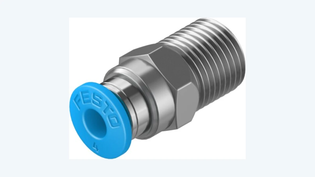
Although R, G, NPT, and metric threads may appear similar in appearance, their thread profiles and sealing methods can differ. Adapters should not be forced into place, and any sealing method other than the one specified by the manufacturer should not be used. In particular, the allowable clamping method and torque when installing a metal thread onto a plastic socket must be determined according to the device’s specifications. When using a elbow connector, it is important to remember that adjusting its orientation after installation does not imply that it will continue to rotate during operation.
Match the tubing/fitting combination to the environment
| Decision area | Question to ask | Risk of an incorrect assumption | Verification document |
|---|---|---|---|
| Flow rate | What are the required flow rates and permitted pressure drops during the fastest cycle? | Accepting the port size directly as the hose diameter. | Dimensioning calculation and variant data page |
| Mechanical compatibility | Is the outer diameter of the hose compatible with the hose clamp system and the required installation depth? | Confusing the inner diameter or inch/metric measurement with the outer diameter. | Technical specifications for hoses and connectors |
| Fluid | What are the pressure-temperature limits for air, vacuum, or water? | Transferring air pressure to another fluid medium | Fluid note specific to the product number |
| Environment | Are there any chemical reactions, welding sparks, hydrolysis, UV exposure, or washing processes involved? | Transferring standard materials into harsh environments | Material and compliance certification documents |
| Motion | Is the line fixed, in an cable carriers or subject to torsion? | Thinking that the term “flexible” implies an unlimited service life. | Dynamic test conditions and installation instructions |
Routing, bending and mechanical protection
The hose and cable must be designed within the actual envelope of the moving shaft. A minimum bending radius does not mean that sharp turns can be made immediately after the connection; there should be no tension or lateral forces near the gland or connector. In the cable tray, the wires must be arranged with sufficient clearance to prevent interference, and the manufacturer’s guidelines for spacing and separation must be followed. Overlapping wires of different outer diameters or loosely arranged cables can increase friction.
Secure tubing away from hot surfaces, sharp edges and welding areas. Protective spirals or sleeves change bending behavior and must be tested as an assembly. Do not use connector bodies as mechanical stops. Moving cables need suitable strain relief and a defined bending zone. Robotic torsion and two-dimensional energy-chain motion impose different stresses; a general dynamic-use rating does not establish suitability for both.
Electrical connections: define the signal task before mechanical compatibility
The electrical selection process begins with the connection diagram on the data sheet of the field device. Information such as the supply voltage, allowable current, PNP/NPN or analog output type, IO-Link port type, number of pins, and functions are recorded. Subsequently, the corresponding input, output, or master ports on the controller are added to the same table. Whether the connector is flat or angled is determined based on the geometry of the control panel and the machine; while an angled connector may reduce the installation space, it can also force the cable routing in a specific direction.
M8 and M12 specify connection thread size only. Check coding, gender, pole count and pin assignment separately. An A-coded sensor cable and an M12 interface coded for data or power may look similar but serve different purposes. Compare the numbered wiring diagrams of both device and cable instead of inferring pin numbers from wire colors. Confusing front and cable-side connector views is a common commissioning error.
The NEBU connecting cable family: interpreting the options correctly
The Festo NEBU series offers configurable options for pre-established or open-ended connections between field devices and the control system. The product page for the 539052 series lists various options on both the field and control sides, including M8x1 A-code, M12x1 A-code, or open-ended connections; cable outlets that can be adjusted to be straight, angled, or in other specific configurations; and a range of 3 to 8 wires/pins. However, this list does not imply that all these features must necessarily be included in a single cable. It is necessary to create a valid combination in accordance with the configuration rules, and then retrieve the technical data for the resulting complete order code.
The table provides values for DC and AC circuits ranging from 0 to 250 V, a current-carrying capacity of 3 to 4 A at 40 °C, cable lengths of 0.1 to 30 m, and protection types such as IP65, IP68, or IP69K. It is explicitly stated in the same document that the protection specifications only apply when the components are properly installed. The standard specifies cable characteristics suitable for use in cable carriers and robots, as well as options for PVC or TPE-U (PUR) insulation. These values refer to the entire family of products; for example, it is not possible to determine that a particular M8 sensor cable has a voltage rating of 250 V, a current capacity of 4 A, and IP69K protection level merely by referring to the table.
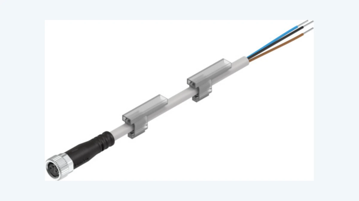
The family data page for the cable carrier option provides test data regarding over five million cycles and a bending radius of 75 mm. This information should be interpreted solely in the context of the specific cable characteristics of the respective cable carrier and Festo’s testing conditions; it cannot be generalized to any NEBU variant or different chain geometries. Factors such as operating speed, acceleration, stroke length, chain radius, temperature, and the presence of other accompanying lines can all affect the actual service life of the product. In robot applications, the torsion angle and the bending limit per meter must also be confirmed in the complete variant documentation.
Protection rating, materials and electromagnetic environment
IP protection is a system-specific feature. The fact that a cable’s data sheet indicates IP65, IP68, or IP69K does not necessarily mean that a connector with loose connections or insufficiently tightened terminals is protected. The compatibility of the connector’s gasket, sealing surface, tightening torque, and cable connection must be considered together. In washable facilities, factors such as the direction, temperature, pressure of the water, and the chemicals used may also require material specifications that go beyond the standard codes.
In machines equipped with power electronics, motor cables, and welding equipment, the routing of signal cables is of great importance. Sensor cables should not be run in parallel over long distances along high-current circuits; rules for crossing and separating these cables must be implemented in accordance with facility standards. For analog cables or communication cables that require shielding, it is also necessary to plan how the shielding will be continued throughout the length of the connector, control panel connections, and equipotential bonding circuits. A standard three-conductor sensor connection cable cannot be used in place of a shielded communication cable.
Workmanship standards for pneumatic and electrical installation
Cut pneumatic tubing squarely and without burrs using a suitable cutter. Do not insert crushed, oval or scratched ends into fittings. Push to the specified insertion depth and gently pull to confirm retention; safely depressurize before removal. When reusing an end, cut away the section with grip marks and check that sufficient length remains for a stress-free connection. Hold the fitting by its wrench flats; do not apply pliers to plastic parts.
Align the electrical connector correctly, seat the pins without force and tighten the locking element as specified. Turn the nut rather than rotating the body and twisting the cable. At open ends, select conductor preparation length, ferrules and terminal torque to the cabinet standard. Label both cable ends with the same device identifier, and update drawings and spare-part lists after variant or length changes. Fit appropriate protective caps to unused connections.
Commissioning: test leaks and signals together
The initial pressurization process is carried out under controlled conditions. The area around the gland is not merely subjected to sensory inspection; instead, its integrity is verified using a leakage detection method in accordance with the plant’s procedures. While the actuator is operating at its maximum speed and under maximum load conditions, the inlet pressure of the valve is monitored. If the speed is lower than expected, the supply line, the valve, the hose, the component in question, and the exhaust pathway are all examined individually. Increasing the pressure at a particular point may actually conceal the underlying bottleneck issues and lead to increased energy consumption.
During the electrical testing, the continuity of each pin connection, any short circuits, and the accuracy of label matching are checked first while the power is turned off. Once power is supplied, the device’s operating conditions under load are measured; the controller’s input and output signals are compared with the actual movement of the machine. The moving axes are slowly rotated through their full range of motion to ensure that the hoses and cables are not stretched, bent, or rubbed against adjacent components. Finally, a cycle test is conducted at the production speed, and any errors are recorded.
Maintenance and spare parts strategy
During periodic inspections, cracks, hardening, color changes, wear, and severe bending should be checked on the surface of the hose; looseness, leakage, and mechanical damage should be examined at the cable gland/fitting. For the cable, signs of external sheath friction, loose connectors, missing seals, and irregular movements in the cable carrier should be observed. It is not appropriate to simply replace a faulty component with one made of the same color or outer diameter; the material, as well as its pressure, temperature, mechanical properties, and electrical characteristics, must match those of the original component or an approved equivalent.
On the spare parts list, the hose reel code, color, and outer diameter; the female connector of the fitting, its shape, and the hose connection; as well as the two-end connections of the cable, the number of pins, length, and mechanical properties are clearly specified. For critical machines, pre-assembled hose-fitting-cable kits can be prepared. This enables maintenance personnel to replace a verified set on-site, instead of having to re-assemble the components manually. If the reason for the component replacement is recorded, recurring systematic issues such as incorrect installation, insufficient bending radius, or inappropriate operating conditions can be identified.
Information required for quotations and project planning
- Type and quality of the fluid, nominal/maximum pressure, vacuum level, temperature, and target flow rate.
- Actuator volume, stroke length, cycle time, simultaneous operation, and allowable pressure drop.
- The outer and inner diameter of the hose, its total length, the color standard, and the minimum bending radius.
- Device-port metric, G, R or NPT threads; sealing and tightening requirements
- Fixed, cable carrier, or robot motion; information regarding stroke, speed, acceleration, cycle duration, and torque.
- Oil, chemicals, water, UV radiation, welding sparks – as well as requirements for clean rooms or the food industry.
- The voltage, current, signal type, PNP/NPN configuration, as well as whether it is analog or IO-Link-compatible of the field device.
- M8/M12 dimensions, coding, male/female design, number of pins, straight/angled connectors, and requirements for open ends.
- Protection class, cable sheath, shielding, route separation, labeling, and acceptance testing
- Required compliance documents, target quantity, spare parts, and standardization policies
Oskon considers connection technology not as a list of accessories to be added later on, but as a measurable component of the automation function. Examples such as Festo PUN-H, QS, and NEBU demonstrate that hoses, connectors, and cables must be selected according to the same principles, within the respective technical specifications. The correct outcome does not depend on simply choosing the right product name; rather, it requires integrating the complete range of options, the specific routing, the installation process, and the acceptance tests into a single comprehensive document.
Official Festo resources
- Festo TR — Pneumatic connection technology
- Festo TR – Pneumatic hoses
- Festo TR — Push-in fittings
- Festo TR — Electrical connection technology
- Festo TR — Connection Cables
- Festo — PUN-H-8X1,25-BL, product number 197385
- Festo official data sheet — PUN-H-8X1,25-BL (11 August 2026)
- Festo — QS-1/8-4, Product Number 153001
- Festo official data sheet — QS-1/8-4 (10 August 2026)
- Festo Official Catalog — QS Quick Star Automatic Connection Fittings
- Festo — NEBU universal connection cable family, product number 539052
- Festo official data sheet — NEBU family (4 December 2024)
- Festo Official Catalog — Universal Connecting Cables NEBU (2026/05)
The information provided on the product pages does not imply that each product model possesses all listed features. Before placing an order, it is necessary to verify the complete product code, the current data sheet, the connection diagram, the applicable environmental conditions, and any required certification documents.