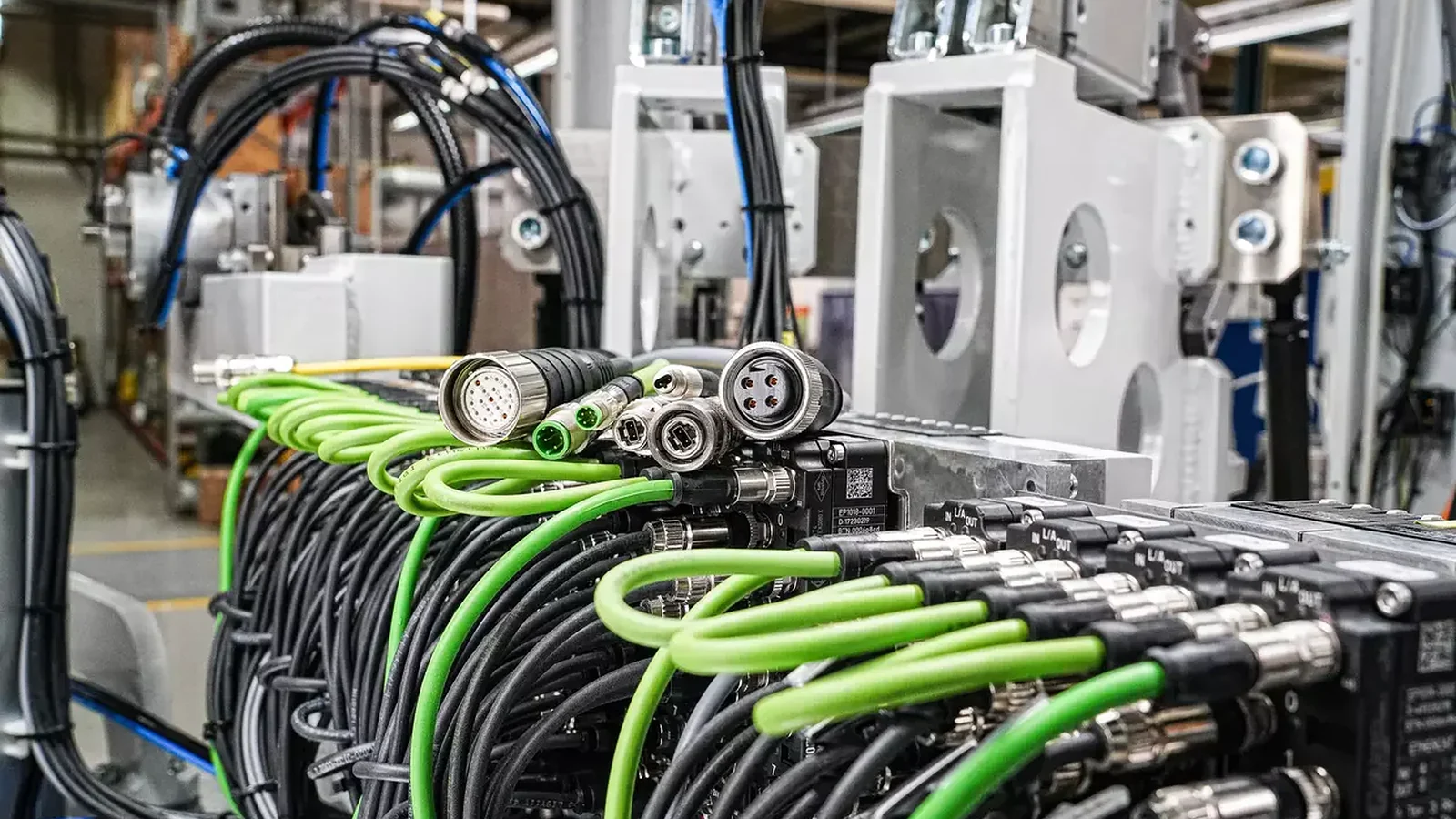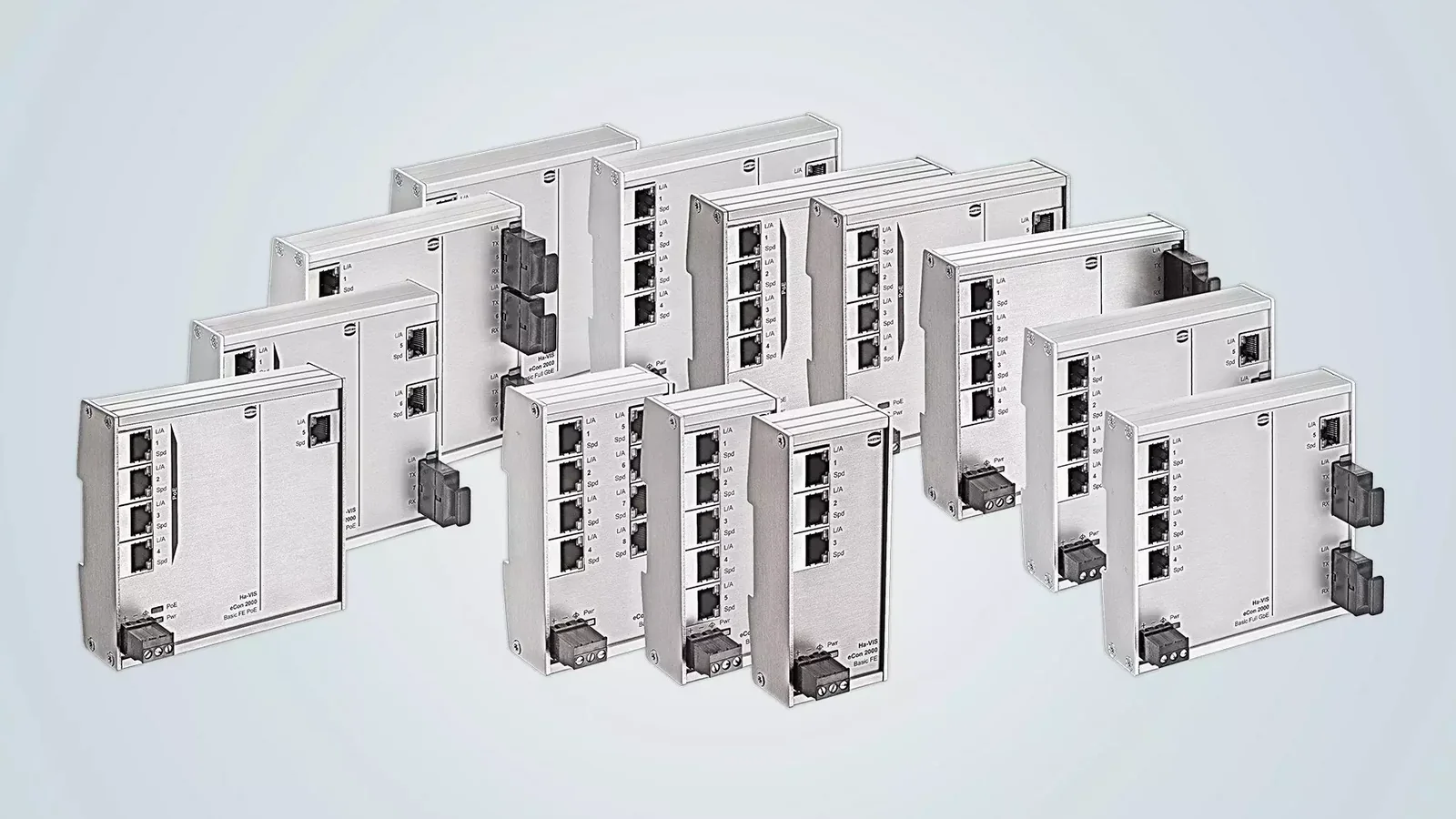
An industrial Ethernet switch is far more than just a small device that transmits packets between ports within a production network. Without considering factors such as the layout of components within the control panel, the direction of field cables, data transfer speeds, the electromagnetic environment, power supply reliability, and maintenance requirements, even a switch with the right number of ports can become a weak link in a project. HARTING’s current product portfolio includes both panel-mounted and field-ready models, as well as Single Pair Ethernet-connected solutions, ranging from the Ha-VIS eCon 2000 to 3000 series. This wide range ensures that the selection process goes beyond simply asking “how many ports are needed?”
This catalog and selection guide are designed to help you match HARTING industrial Ethernet switches with the actual requirements of your automation projects. The family names indicate the general layout and application of the switches, while parameters such as the number of ports, Fast Ethernet/Gigabit Ethernet class, interface type (copper/fiber), PoE functionality, temperature range, protection level, and power supply specifications may vary depending on the specific model. The numerical examples mentioned in this text refer only to the products explicitly specified; they should not be considered applicable to all members of the same series. For confirmation, please refer to the latest technical data sheets, installation instructions, and network compatibility specifications.
Define the network task before choosing a product family
Before starting the selection of switches, it is necessary to identify the network nodes and data flow patterns. Connections such as those between PLCs, remote I/O devices, HMIs, drives, robots, cameras, engineering stations, and higher-level systems each have distinct traffic characteristics. For each connection, it is essential to record the protocol used, the expected average and peak data volumes, the latency tolerance, the port speed, the physical environment, and the consequences in the event of a fault. While camera footage requires high bandwidth, cyclic I/O traffic can function with smaller packets but requires predictable timing patterns. Failing to make these distinctions, the total bandwidth selected may seem sufficient on paper, but the performance of critical traffic streams will remain uncertain.
The decision regarding whether to use a star, line, or mixed topology must take into account the physical layout of the equipment, the length of cable runs, and ease of maintenance access. Simply having a device with two power terminals or a network configured in a ring shape does not automatically ensure redundancy. It is also necessary to verify the functions supported by the switch, the behavior of end devices, and the acceptable recovery time in the event of a fault. The eCon examples shown in this guide refer to unmanaged switches. If VLAN, SNMP, port mirroring, managed ring protocols, or advanced security policies are required, the associated management needs should be documented as a separate technical requirement, and it must be confirmed that the selected product actually provides these functions.
Ha-VIS eCon 2000: flat housings and front cable access
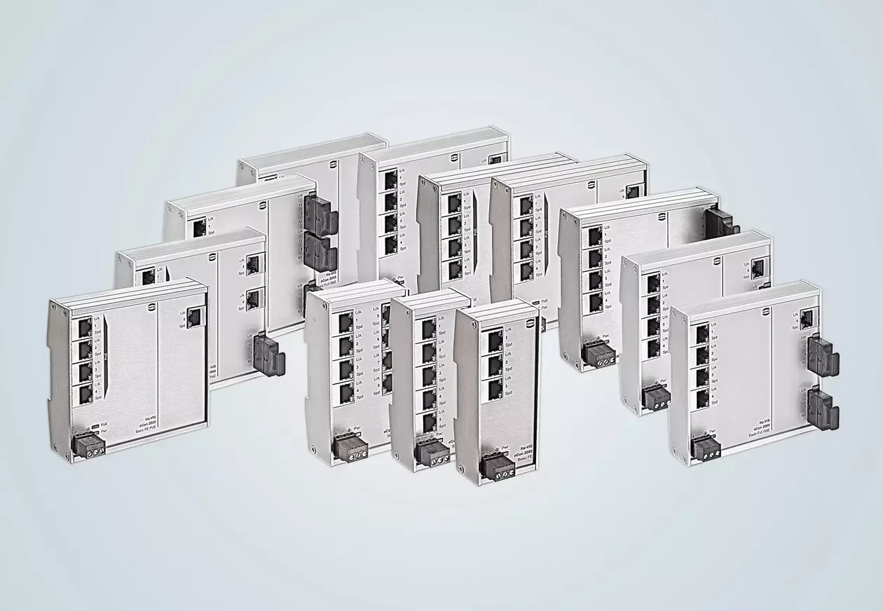
HARTING positions the ha-VIS eCon 2000 series as flat-body, unmanaged Ethernet switches. According to the official product page, this series offers options up to 16 Fast Ethernet ports or up to 7 Full Gigabit ports; certain models are available in RJ45 and fiber-optic variants, and some also support PoE+. These specifications represent the range of options available within the series and do not imply that all features are necessarily included in any single device. The flat body design may be particularly useful in control panels where the depth in front of DIN rails is limited but there is sufficient horizontal space along the rails. The front-facing layout of the ports facilitates installation and maintenance; however, factors such as cable connectors, bending radius, and the distance required to close the cover must still be taken into account during 3D layout planning.
A specific example is Ha-VIS eCon 2050BT-A, 24 02 005 0000 is described on HARTING’s product page as an unmanaged Fast Ethernet switch with five 10/100 Mbit/s RJ45 ports. The product’s nominal power supply is 24 or 48 V DC, its operating temperature range is −40 to +70 °C, and its protection level is IP30 when properly installed. The same page also indicates that it can be mounted on DIN rails, supports twisted-pair connections over distances of up to 100 meters, and does not incorporate PoE functionality. These specifications apply specifically to this product model and not to the entire eCon 2000 series. For information regarding the standard temperature variant, the Gigabit model, or the PoE version, please refer to separate data sheets.
Ha-VIS eCon 3000: narrow layouts and varied connections
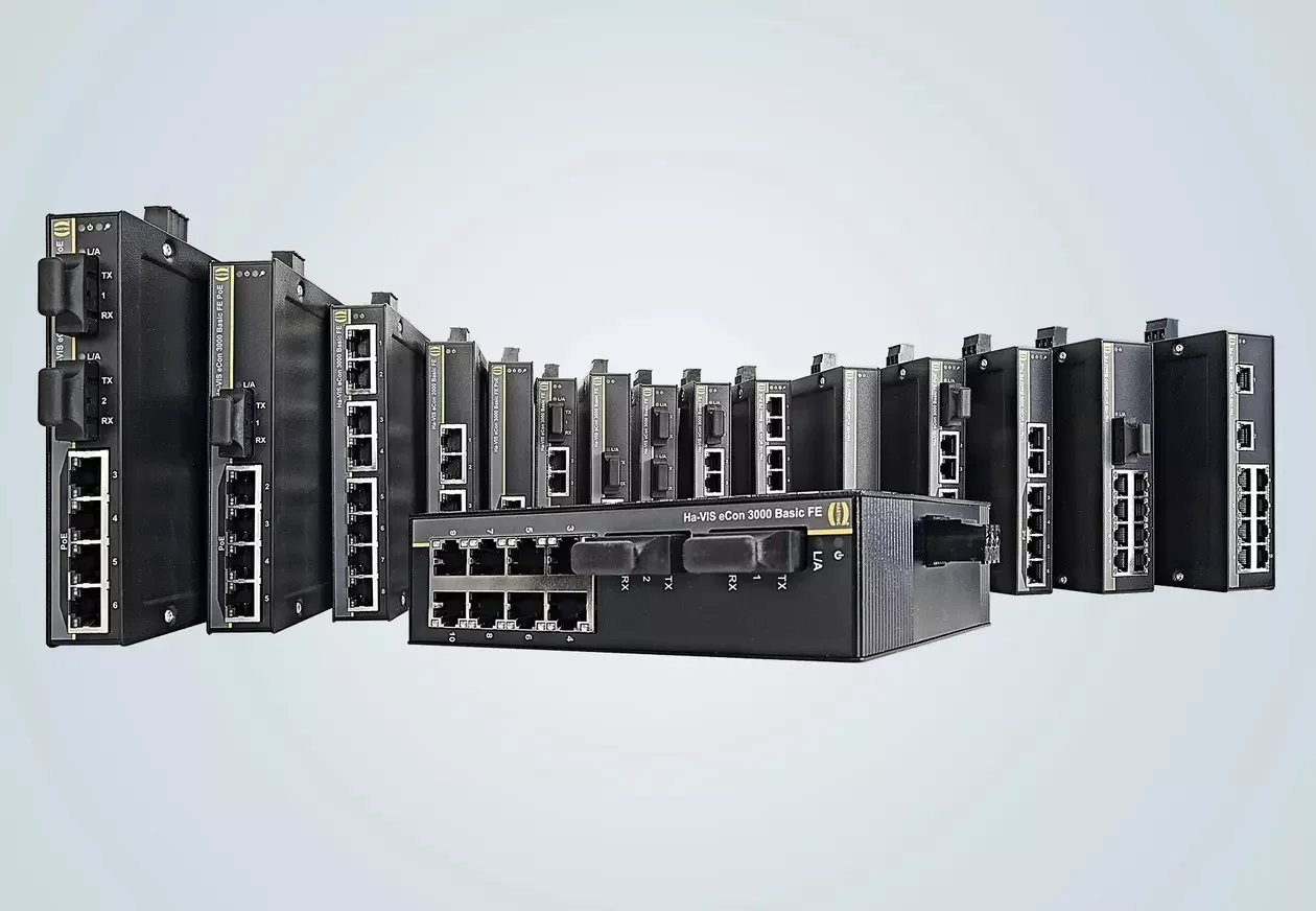
The Ha-VIS eCon 3000 series is characterized by its compact design, which aims to achieve high packing density along DIN rails. According to HARTING’s specifications, this series offers options up to 10 Fast Ethernet ports or up to 7 Full Gigabit ports. Variants based on RJ45, fiber, and SFP interfaces are available in the product range; some models are equipped with PoE+ functionality, while others feature a wide operating temperature range. However, the term “compact” does not necessarily imply automatic space savings for each control panel. Factors such as the location of cable outlets at the front or top, the need for adequate air circulation around adjacent devices, accessibility of terminals for maintenance, and the allowable bending degree of fiber cables must all be taken into consideration when arranging devices along the rail.
Ha-VIS eCon 3043GBT-AC, 24 03 404 3300 is a product example that clearly outlines the requirements for both copper and fiber uplinks. HARTING’s list classifies this model as an unmanaged Full Gigabit Ethernet switch, featuring a total of seven ports: four 10/100/1000 Mbit/s RJ45 ports and three 1000 Mbit/s Mini-GBIC slots. The same specifications—24/48 V DC power supply and an operating temperature range of −40 to +70 °C—apply to this product as well. If an SFP module is also selected, the fiber type, wavelength, single-mode/multi-mode configuration, connector type, optical budget, and compatibility with the switch must all be verified within the same product documentation. The presence of SFP slots does not necessarily mean that all types of optical modules can be used with this switch.
Traffic determines the choice of Fast Ethernet, Gigabit and fibre
Fast Ethernet may be sufficient for a sensor node or a machine that generates limited amounts of data; however, high-resolution cameras, extensive data transfer requirements, large project backups, or heavy traffic in upper-layer systems may necessitate Gigabit connections. The decision regarding which connection type to use should not be based solely on the labeled speed of each port. Instead, the overall switching performance of the switch—taking into account simultaneous active connections, packet sizes, and congestion levels on the uplink—should be considered. Unmanaged switches do not automatically allocate traffic based on project priorities. Rather than combining critical control networks with high-volume data or office traffic within the same broadcast domain, it is essential to review the cell architecture and upper-layer design carefully.
In copper Ethernet connections, the channel quality is not determined solely by the switch port itself; the cable, connectors at both ends, panel connections, and on-site installation all need to be tested. For long distances, high electromagnetic interference, or the need for galvanic isolation, fiber optic cables can be considered. While choosing fiber optic solutions can reduce the risk of interference, issues such as dirty connector surfaces, incorrect SFP modules, excessive bending, or insufficient optical power can still lead to new faults. After installation, conducting copper channel tests or optical power measurements provides more reliable evidence of successful connection than merely visual inspections.
Calculate PoE and supply power as separate power budgets
A PoE-enabled switch can reduce the need for separate field power supplies by providing power to cameras, access points, or other compatible end devices via the data cable. However, the mere indication of “PoE+ available” is not sufficient; it is essential to compare the class of power support offered by each port, the switch’s total PoE budget, the power consumption of connected devices under both normal and extreme conditions, as well as any limitations related to supply voltage and temperature. It should not be assumed that all ports can provide their maximum power output simultaneously. The PoE functionality and power budget of the selected HARTING product must be clearly verified on the product’s technical specifications page.
The voltage tolerance, current capacity, terminal blocks or connectors, reverse polarity protection, overcurrent protection, and earthing methods of the switch’s own 24/48 V DC power supply are all subject to evaluation. If redundant power supply is required, it is necessary to verify whether the power sources are truly independent, rather than simply connecting two cables. If two lines are connected to the same fuse, the same power source, or the same distribution terminal, a common failure point will arise. Voltage drop, circuit protection measures, and the thermal design of the control panel must all be calculated taking into account the PoE load.
Field-mounted M12 switches and protection ratings
In areas near control panels, or in environments subject to vibration, dust, or moisture, field-oriented products such as the Ha-VIS eCon 4000 and 7000 can be considered. For example… Ha-VIS eCon 4080-B1, 20 77 208 3001 is an unmanaged Fast Ethernet switch listed with eight M12 D-coded 10/100 Mbit/s ports, 24/48 V DC nominal supply, and a −40 to +70 °C operating range. Ha-VIS eCon 7050-B1, 20 70 305 3943 is listed with five M12 D-coded Fast Ethernet ports and IP65/IP67 protection when mated.
In these examples, the IP rating specified does not apply to the open ports. The compatible cable connectors must be mated using the correct torque; unused ports should be covered with appropriate caps, and all installations must be carried out in accordance with the manufacturer’s instructions. The M12 D-code Fast Ethernet interfaces and X-code Gigabit interfaces differ both mechanically and electrically; even if they have the same number of ports, they cannot be used interchangeably. Requirements regarding cleaning chemicals, UV exposure, corrosion resistance, vibration, and impact resistance cannot be met solely by the IP rating; it is also necessary to check the material composition, certifications, and the scope of environmental testing for the selected products.
Assess Single Pair Ethernet within a migration architecture
The Ha-VIS eCon 3000 SPE options within HARTING’s product portfolio enable distribution or media conversion functions between traditional multi-pair Ethernet and Single Pair Ethernet field connections. For example, Ha-VIS eCon 3026 GBT-AT1-SPE, 24 05 402 6400 is listed on the official product page as a Gigabit Ethernet switch with a total of eight ports, a nominal power supply of 24/48 V DC, and an operating temperature range of −40 to +70 °C. The port types, T1 connection standard, compatibility with compatible devices, and cable length of the same product should be confirmed by referring to the port specifications on the current page.
SPE is not merely about reducing the number of conductors in an RJ45 cable. The physical layer, connector design, cable impedance, shielding, power transmission requirements, and support for the opposing device together constitute a complete channel system. It should not be assumed that a existing sensor or PLC port can be used directly without modification. If a media converter is employed, the response to changes in speed, latency, error behavior, and power loss on both sides must be thoroughly tested. When transitioning to new technologies, spare parts and the testing equipment required by field personnel must also be included in the project scope.
| Project requirement | HARTING solution to consider | Information to verify against the product code |
|---|---|---|
| Control panel with limited depth; front-cable connection. | Ha-VIS eCon 2000 in flat-body versions | Number of ports and speed, RJ45/fiber, PoE, temperature, power supply, and dimensions |
| Narrow layout along the DIN rail | Ha-VIS eCon 3000 narrow-housing variants | Copper/SFP distribution, uplink, cable outlets, thermal clearance, and certifications. |
| M12 field connections outside the enclosure | The relevant eCon 4000 or 7000 product. | D/X coding, Fast/Gigabit, matched IP status, temperature, and mounting information. |
| Connecting SPE field devices to the upper-level network | eCon 3000 SPE switch or media converter | Physical port characteristics, T1 standard, speed, cable length, and compatibility with the opposite end device. |
| Fiber uplink or long/distorted transmission paths | The eCon variant with fiber ports or SFP slots | SFP compatibility, fiber type, wavelength, optical power budget, and connector. |
| Powering the camera or access point via cable. | Specific variants that support PoE/PoE+. | Class per port, total power budget, and derating of power supply and temperature specifications |
Commissioning and diagnostic plan
Although an unmanaged switch can be set up and used immediately, network validation is still required. The speed and duplex mode of each port, error counts (if available), end-to-end latency, packet loss, and performance under peak traffic conditions must all be measured. Tests for power-on/off functionality, PLC reconnection, restoration of camera feeds, and the behavior of higher-level system sessions should also be conducted. LED indicators must be clearly documented in the maintenance instructions; it should be indicated both on the schematic diagram and on the label which port connects to which device.
If unmanaged devices do not provide access control based on local VLANs or ports, security measures and segmentation should be implemented using managed switches, routers, or firewalls at the higher layer. Access to unused physical ports should be restricted using panel locks and field connector covers. The network diagram, IP addressing plan, switch model number, SFP list, cable test report, and information on spare parts should all be included in the as-built documentation. If the product includes software or firmware, its version numbers and vendor updates should be tracked throughout its entire lifecycle.
Data required for a quotation
- Share the list of nodes: Specify the devices to be connected, the protocols to be used, the port speeds, their locations, and their critical operational tasks.
- Draw the topology: Represent star, line, uplink, and higher-level network connections, along with the associated distances and redundancy requirements.
- Describe the traffic profile: Specify the peak load and latency limits for control, visualization, HMI, engineering, and data collection processes.
- Select the port environment: Specify the requirements for RJ45, M12 D/X, fiber/SFP, or SPE, along with details about the cable and the corresponding connector.
- Calculate the PoE load: List each end device’s class, maximum consumption, inrush current, and simultaneous operation scenarios.
- Describe the electrical supply: Add in the nominal voltage, tolerance voltage, fuse, spare power supply, earthing, and voltage drop considerations.
- Classify the environment: Record the temperature, humidity, condensation, dust, water, chemicals, vibration, impact, EMC conditions, as well as the installation location.
- Describe your management requirements: If VLAN, SNMP, port mirroring, ring topology, security features, and remote diagnostic capabilities are required, include them explicitly in the requirements document.
- Define the acceptance test: Predefine the criteria for cable certification, packet loss, load, power outages, and recovery after errors occur.
Oskon and HARTING begin the selection process for industrial Ethernet switches not based on product images, but rather on data flow requirements and field conditions. The right solution is one that not only has a sufficient number of ports, but also physically fits within the control panel, supports the required cable infrastructure, operates within specified power and temperature limits, does not conflict with network management requirements, and can be tested in the field. Availability and delivery times must also be confirmed at the time of the offer; this guide makes no commitments regarding stock availability or automatic suitability for specific applications.