A crane cable is not merely a conventional power cable that transmits energy; rather, it is an essential component of the mechanical system that enables the continuous lifting of loads. The cable can be wound and unwound on a drum, form loops between the trolley cars, extend along the crane bridge, or be suspended vertically under its own weight. In each configuration, the combination of factors such as bending, tension, torsion, acceleration, impact, and external environmental influences varies. Therefore, the correct selection of a crane cable must be based not only on its voltage rating and cross-sectional dimensions but also on the entire operational requirements of the crane.
In Birtaş Kablo’s product portfolio, the products BIRTFLEX CRANE, BIRTDRUM, and BIRTFESTOON represent different application areas. The similarity in their names does not imply that they can be used interchangeably. The winding characteristics of drum cables, the requirements for hanger and track systems in festoon cables, and the tensile and torsional loads experienced by freely moving crane cables all differ significantly. Before selecting a product, it is essential to first draw up a mechanical layout, taking into account the requirements for power transmission, control systems, and shielding.
Define the cable handling mechanism first
In the drum-type system, the cable is wound around a body in multiple layers. With each cycle, the cable is both bent and pulled; if there are multiple winding layers, the lower layers may be subjected to pressure from the upper ones. In the festoon system, the cable hangs in loops from the carrier trolleys. As the trolleys move closer together, the loops become deeper; when they move apart, the loops expand. In systems with free hanging or trolley connections, the cable may experience more irregular swinging and torsion. A cable chain, on the other hand, creates a directed and repetitive bending motion.
When the specification is limited to the term “crane cable,” it becomes unclear which motion parameters the manufacturer will assume. Information such as the type of crane, the horizontal and vertical stroke distances, the lifting capacity, the movable length of the cable, the number of winding layers, the diameters of the drum and guide rollers, the number of cycles, the operating speed, the acceleration, as well as the wind and temperature conditions should be provided. It is also necessary to indicate whether the cable is capable of supporting its own weight, whether an additional traction element is used, and the load generated at the connection points.
| Mechanism | Typical stress | Project check |
|---|---|---|
| Winding the drum | Repeated bending, pulling, and layer pressure. | Diameter of the drum/reel, winding direction, line tension, and number of layers. |
| Festoon | Suspended cable loops, trolley movement, and swing | Loop length, trolley spacing, clamps, and minimum bend radius |
| Trolley and crane bridge | Horizontal motion, vibration, external environment | Traveling speed, acceleration, line length, and mechanical guide. |
| Vertical free hanging | Its own weight, tensile force, and torsional force | Supporting component, hanging height, and tension relief. |
| cable carriers | Directed bending, friction, and acceleration | Chain radius, fill, dividers, and fixing points |
BIRTFLEX CRANE for free movement and heavy-duty applications
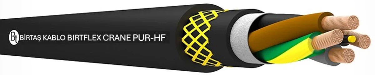
BIRTFLEX CRANE PUR-HF is described by Birtaş Kablo as a crane and winding cable with a highly flexible PUR sheath and TPE insulation. Its official applications include drum winding/unwinding systems, cranes, drive units, and rail-mounted traction motors, as well as in heavy-duty applications such as lifting, transportation, and conveyor systems. The description specifies that it is designed to withstand mechanical stress, bending, and tension, and can be used in oily, dry, humid, or wet environments.
The manufacturer specifies the resistance of the outer sheath to tearing, wear, cracking, as well as the effects of weather conditions, cold, oil, various chemicals, hydrolysis, microorganisms, ozone, and UV radiation. However, this broad coverage does not imply unlimited compatibility with all chemicals or in all environments. In locations such as ports, steel plants, or waste dumps, substances like fuel, hydraulic oil, salt, cleaning chemicals, and hot surfaces must be specifically considered; it is essential to verify that the selected product is compatible with the relevant current technical specifications.
Shielded BIRTDRUM C-PUR-HF for reeling applications
In reel cables, the stability of the winding is just as important as the electrical conductivity of the conductors. The cable should be inserted into the reel at the correct angle and not forced in the opposite direction; moreover, the guiding rollers must be suitable for the cable’s diameter. The reel groove, winding pitch, and tensioning system are designed to prevent the cable from being compressed or the layers from sticking together. When uncoiling the cable from the reel, laying it in a coil on the ground or feeding it while twisting it around its axis can generate internal stress before it is even connected to the circuit.
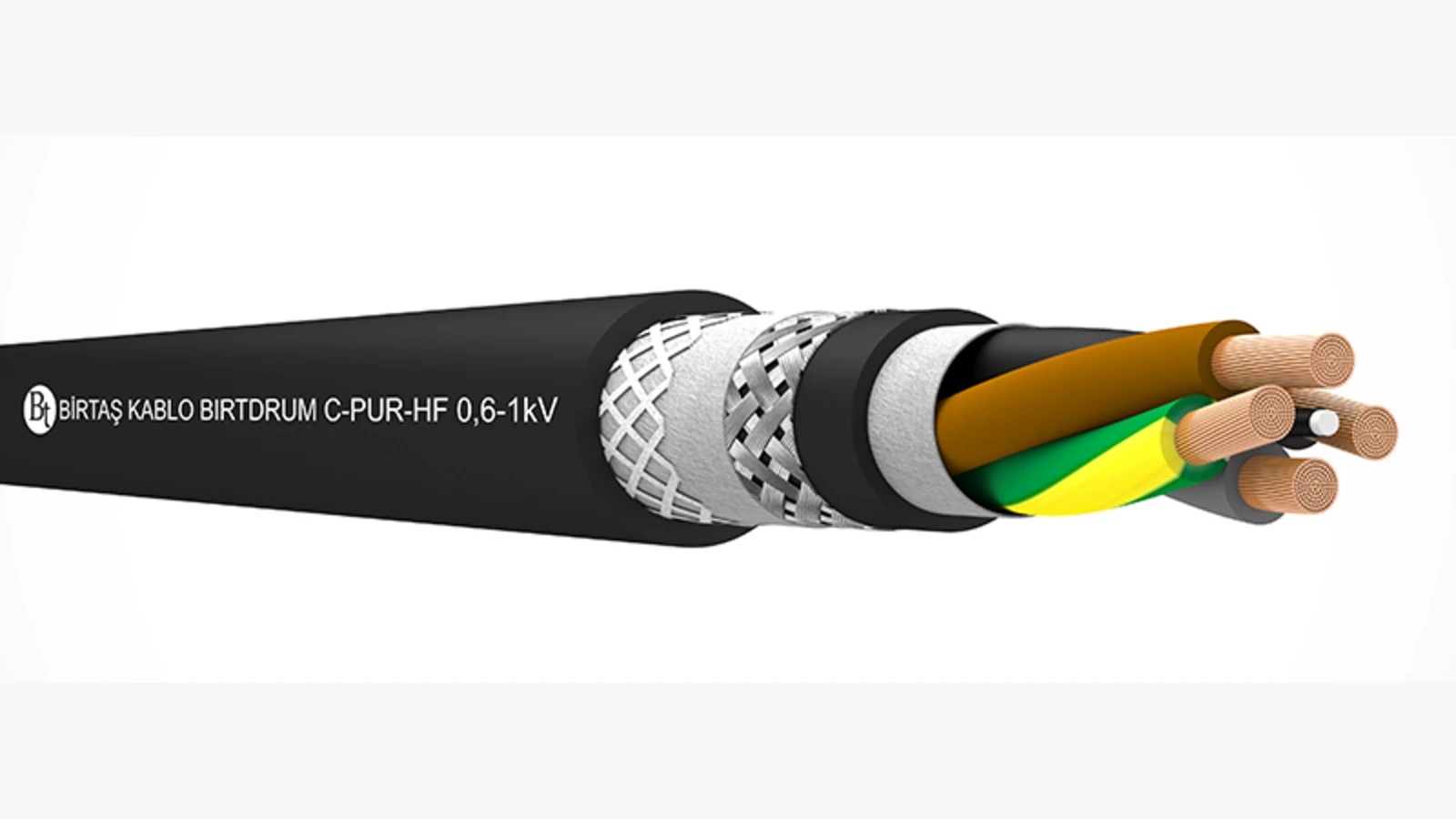
On its official product page, BIRTDRUM C-PUR-HF is described as a crane and winding cable with TPE insulation, a shielded design, and a flexible PUR sheath. The composition includes EN 60228 Class 5 flexible copper conductors, a central TPU-coated textile core, additional filler materials as needed, a tin-plated copper wire mesh as a shielding layer, a polyester twist-proof protective layer, and a halogen-free PUR outer sheath. The shielding layer serves to protect against external electrical interference and should not be confused with the protective grounding system.
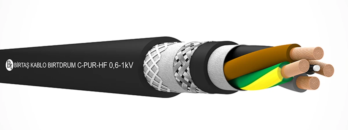
The specifications published by the manufacturer for this product include a declared voltage of 0.6/1 kV, a temperature range of −50 to +90 °C for fixed applications, and −40 to +90 °C for mobile applications. The minimum bending radius when in motion is specified as 7.5 × D. The maximum allowable torsion is ±50°/m, and the maximum tensile stress on the conductor cross-section is 25 N/mm². The maximum traveling speed of the winding system is stated to be 180 m/min in the horizontal direction and 120 m/min in the vertical direction; for festoon and cable chains, this speed is 240 m/min.
These values should not be directly copied over as “permitted operating points” for design purposes. Their meaning is determined by the specific product family, test conditions, and proper installation; simultaneously applied forces such as tension, temperature, speed, and radial loads can affect the service life of the product. The design should include a safety factor based on the product’s nominal operating values, and the actual outer diameter of the product must be used. Additionally, the complete mechanical specifications must be provided to the manufacturer. These values must not be automatically transferred to other BIRTDRUM or BIRTFESTOON products.
BIRTFESTOON PUR-HF for festoon systems
In a festoon arrangement, the cables form controlled loops between the carrier trolleys. The depth of the loops and the spacing between the trolleys are calculated in such a way as not to bend the cable below its minimum bending radius. The clamps must distribute the load without crushing the cable; appropriate carriers must be used for both flat and round cables. Collisions between the trolleys, wear on the wheels, or misalignment of the tracks can cause damage to the cables. Simply replacing the cables does not eliminate the faults resulting from a damaged mechanism.
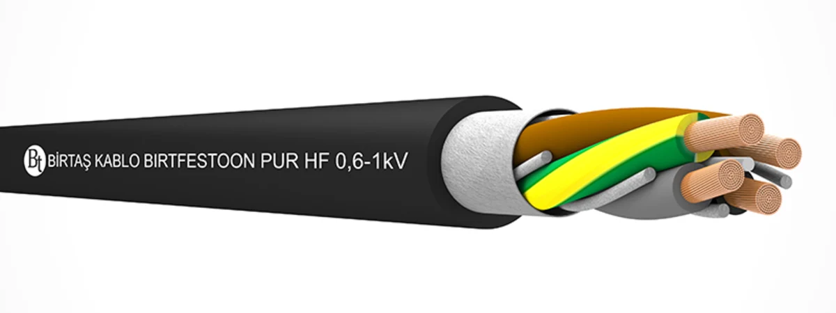
BIRTFESTOON PUR-HF is a family of power and control crane cables with TPE insulation and a flexible PUR sheath. Official data sheets list options featuring either single-conductor high-cross-section cables or multi-conductor power and control cables; this diversity is designed to enable the same cables to perform different electrical functions within the same mechanism. When placing an order, it is necessary to specify not only the family name but also the number of conductors, cross-section, protective-earth arrangement, full product code, and approximate outer diameter. The dimensions of the cable fittings and clamps will also be determined based on the selected outer diameter.
Choosing shielded and unshielded constructions
In a crane, the electrical characteristics of control contacts, analog measurement signals, encoder feedback, drive motors, and safety signals are not identical. High-frequency common-mode currents may occur at the output of variable-frequency drives; the connection between the shielded wires and the motors must be designed in accordance with the manufacturer’s EMC specifications. Low-level control signals should be kept as separate as possible from the power lines. A design such as the shielded BIRTDRUM C-PUR-HF can offer advantages under certain noise conditions; however, if the shielding and termination are not properly implemented, the expected benefits will not be achieved.
The screen connection, as well as the panel input connectors, the connections on the drum, the terminal blocks, and the entire design along the moving parts must be carefully planned to ensure continuity. Connecting the wires with a long tail increases impedance, especially at high frequencies. 360-degree screen clamps, appropriate metal connectors, and equipotential connections should be used according to the specific project requirements. The PE conductor is intended for electrical safety purposes only and does not replace the screen; moreover, the screen itself should not be used as a PE conductor.
Cross-section and voltage drop calculations
In the context of motor or hoisting applications, the cable cross-section is determined based on factors such as continuous current, duty cycle, ambient temperature, heat dissipation of the wrapped cable, cable grouping, and voltage drop. When multiple layers of cable are wrapped around the drum, the thermal conditions can differ from those in an open-air installation. Motor starting, brake coils, or the load on the drive unit can cause short-term variations in current and voltage behavior. Even if the manufacturer provides reference data regarding current capacity, the final selection of cable specifications must be based on industry standards and the actual installation conditions.
On long crane lines, voltage drop can affect not only the power performance but also the reliability of the braking and control systems. As the cross-sectional area of the conductor increases, the outer diameter, weight, and minimum bending radius of the cable also increase, which in turn alters the geometry of the drum and the associated components. Therefore, electrical and mechanical calculations must be performed iteratively, rather than sequentially. After replacing the cable, the capacity of the reel, trolley, clamp, and drum must be reevaluated.
Vertical runs and tensile force
A vertically installed cable exerts increased tension at its upper connection point due to its own weight. It is impossible to determine its suitability solely based on its cross-sectional dimensions, without knowing its length, weight per meter, and dynamic acceleration. Even in products that feature a central support element, it is crucial to understand how the force is transmitted to the cable. Hanging the cable solely from its electrical connector imposes mechanical stress on its contacts and sealing components.
The strain-relief component must distribute force without damaging the sheath, and must not prevent bending along the line of motion. It should be remembered that in a vertical drum system, the manufacturer’s specified horizontal and vertical speed values may differ. Dynamic forces resulting from wind, load fluctuations, and emergency stops must also be taken into account. When a carrier rope or separate mechanical support is used, the length and flexibility of the component must be carefully matched to those of the electrical cable.
Drum and pulley geometry
The minimum bending radius is measured with respect to the centerline of the cable. When determining the diameter of the drum, it is essential to carefully read the relevant description in the product brochure. While a smaller drum may save space, it will generate higher cycle stresses on both the conductor and the shielding. The diameters of the reversing drum and the main drum should be checked separately. The groove profile should not compress the cable, the cables should not be wrapped crosswise, and the line entry angle must be maintained properly.
The winding direction of the cable must correspond to its natural orientation during production and be compatible with the movement of the system. Before initial installation, the reel is inspected for damage, sharp edges, welding slag, and proper alignment. The cable should be unloaded from the transport reel in the correct direction; it must not be dragged on the ground, and bent sections must not be forced straightened. Excessive force applied during installation can lead to future operational failures.
Commissioning acceptance tests
- Product identity: Compare the reel label with the product code, conductor cross-section, manufacturing information, and length specified in the purchase record.
- Mechanical inspection: Inspect the sheath, drum, reel, carriage, clamp, connection points, and tension-relief devices.
- Electrical verification: Test core continuity, protective earth, insulation, and shield connections using methods suitable for the connected equipment.
- Low-speed cycle: Monitor the winding, looping, and guiding behavior throughout the entire stroke; look for any signs of crushing or torsion.
- Gradual loading: Increase speed and load in a controlled manner; record motor current, voltage, temperature, and mechanical performance.
- Emergency test: Under the safety procedure, observe the effect of the shutdown and restart on the cable.
Maintenance and fault analysis
During periodic inspections, conditions such as sheath wear, flattening, cracking, bulging, local changes in the outer diameter, screen marks, and color changes are checked. The drum groove, reel bearings, festoon cars, and clamps are also examined together with the cable. Repeated damage at the same location usually indicates issues with the line’s geometry, tension, or alignment. Replacing the cable without addressing the mechanical cause will only result in the fault recurring.
Maintenance records must include information regarding the location of the fault, the operating hours, the cycle count, the ambient conditions and load conditions, as well as photos and the label of the removed component. The new cable must be selected based on its full product code; merely specifying “PUR crane cable with the same cross-section” is insufficient. Among products that appear similar, the details regarding the shield, the conductor, the torsion protection measures, and the mechanical and electrical specifications can vary. In cases where additional components are required, it is essential to ensure that their installation does not exceed the permitted movement range and that their electrical and mechanical compatibility is verified in accordance with the project specifications.
Project data required for a quotation
- Crane type, drum/festoon/trolley arrangement, horizontal and vertical movement distances
- The diameter, groove design, and number of winding layers of the drum and all the guide rollers.
- Traveling speed, lifting speed, acceleration, cycle time, operating class, and emergency stop behavior.
- The length at which the cable can support its own weight, as well as information regarding its tensile strength and torsional properties.
- Voltage, current, motor/drive type, core count, cross-section, protective earth, and shielding requirements
- Ambient temperature, UV radiation, oil, chemicals, water, salt, dust, and mechanical stress.
- Required halogen-free and fire-performance properties, industry standards, certificates, and test records
- Cable length, installation allowance, termination method, type of cable glands, and quantity of spare parts.
When selecting the crane cables from the Birtaş Kablo range, Oskon considers the electrical specifications in conjunction with the mechanical transmission system and the same model. Once the choice between BIRTFLEX CRANE, BIRTDRUM, or BIRTFESTOON is made, the full product code, outer diameter, range of motion, and environmental resistance requirements are verified directly from the official data sheet. The result is not just a simple power cable, but a crane cable solution that can be protected during use, tested, and for which maintenance records can be kept.
Official technical resources
- Birtaş Kablo – Crane Cables
- Birtaş Kablo – Cables for Crane and Drum Applications
- Birtaş Kablo – BIRTFLEX CRANE PUR-HF
- Birtaş Kablo – BIRTDRUM C-PUR-HF
- Birtaş Kablo – BIRTFESTOON PUR-HF
The technical specifications apply specifically to a particular product family and its variants. Before placing an order, it is necessary to confirm with the manufacturer the exact product code, the current data sheet, the mechanical installation limitations, the relevant certifications, and the availability of the products.