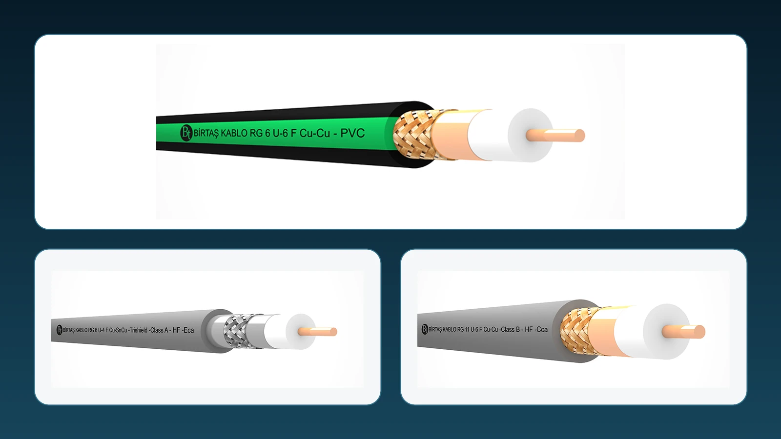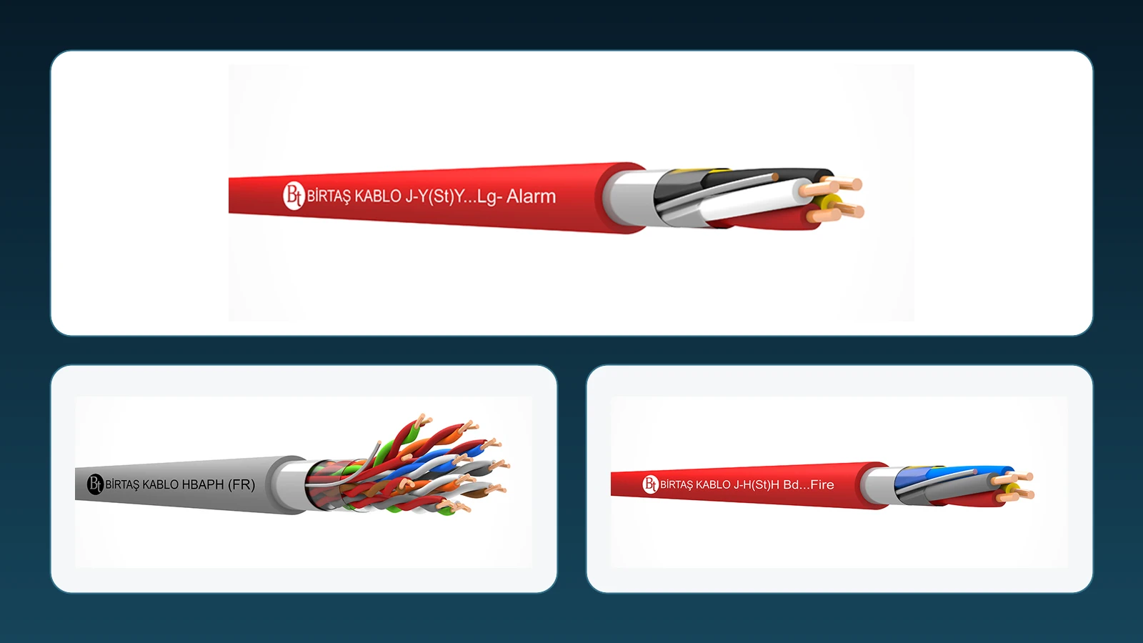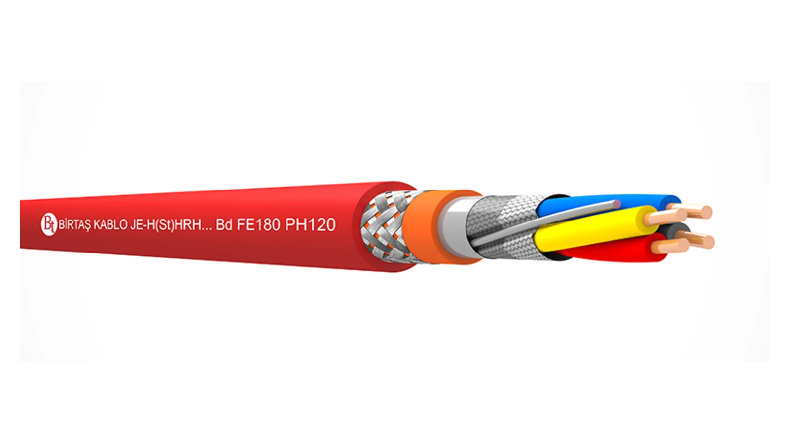
The selection of data and signal cables is not merely about determining the number of conductors and their cross-sectional areas. Analog measurement circuits, dry contacts, RS-485 serial communication, field data lines, and Ethernet networks rely on different electrical parameters—capacitance, characteristic impedance, twisted-pair geometry, shielding structures, signal attenuation, and operating frequencies—to ensure the integrity of the transmitted information. The ability of a cable to physically connect to a device does not necessarily mean that it is suitable for the specific protocol being used.
Birtas Kablo categorizes its data and signal products into signal cables, RS 422/485 cables, BUS cables, and Cat cables. This catalog and selection guide presents the LIYCY, LI02Y(St)CH-PIMF RS-485, and CAT6 U/UTP products through three different application examples. Since the technical specifications vary among products within the same family, the final decision should be based on the complete product code, the latest product information, the physical layer requirements of the device manufacturer, and the actual length of the line to be installed.
First define the physical layer of the information being carried
“A data cable” does not represent a single technical category. A 4–20 mA analog circuit often serves for low-frequency measurement purposes, while RS-485 is a differential serial communication protocol. Ethernet requires balanced twisted-pair cables and category-specific performance standards; different field data communication systems, in turn, have distinct requirements regarding impedance, number of conductors, and shielding arrangements. The presence of the same type of connectors on a device does not necessarily mean that the cables used for these systems share identical specifications.
The selection form should include the protocol name and version, data speed, line topology, maximum end-to-end length, number of nodes, termination type, device connector, and grounding method. Information such as analog signal or sensor power supply, loop resistance; for pulse or encoder signals, edge speed, and receiver structure; and for Ethernet connections, permanent connection status and category of channel components must also be specified. A vague definition of “shielded data cable” can lead to different interpretations throughout the project.
| Task | Key cable characteristic | Common mistake |
|---|---|---|
| General control and electronic signals | Number of conductors, cross-section, capacitance, overall shielding. | Using a fixed indoor environment product in outdoor conditions or in continuously moving environments |
| Analog measurement | Pair arrangement, shielding, loop resistance, and interference separation | Distributing the supply and return conductors across different pairs. |
| RS-422/485 | Characteristic impedance, twisted pair, low capacitance | Star topology, or uncontrolled branch and termination systems. |
| Industrial BUS | Physical layer and shield specific to the protocol | Selecting a different BUS cable merely because the core colors look similar |
| Ethernet | Category, frequency, balanced signal, and channel integrity. | Simply verifying the cable while ignoring the plug, panel, and patch cables. |
LIYCY: shielded general-purpose data and signal cables
LIYCY is available in Birtaş Kablo’s portfolio as a PVC-insulated, shielded data and signal cable. It is used for the transmission of electronic signals in general control, instrumentation, communication, and automation systems. The tin-copper braided shield provides protection against external electromagnetic interference. This product family offers a wide range of conductor counts and cross-sectional sizes; the outer diameter and cable weight vary depending on the selected model.
It is incorrect to interpret “LIYCY” as “shielded cable suitable for any data protocol.” If a particular protocol requires specific characteristic impedances, twisted-pair construction, or high-frequency performance, these parameters must be explicitly specified in the LIYCY product specifications. A variant suitable for general digital I/O or analog control applications is not necessarily compatible with RS-485 or Ethernet networks. Furthermore, the manufacturer’s instructions clarify that products in this category are designed for indoor use only and are not intended for external applications, especially direct burial in the ground.
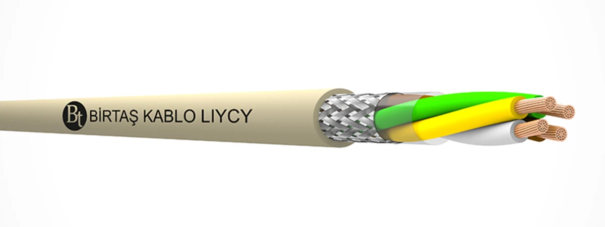
When selecting the number of conductors, not only the existing I/O list but also common reference conductors, the policy for using spare conductors, and the connection layout of the shielding layers must be taken into consideration. How to isolate any unused conductors at both ends is specified in the project standards. Combining a large number of low-level signals in the same cable can simplify installation, but the impact of crosstalk between channels and the maintenance requirements must also be evaluated. For sensitive analog signals, a paired or individually shielded construction may be more appropriate.
Impedance and topology work together in RS-485 cabling
RS-485 transmits differential signals over a balanced pair of wires. For proper functionality, various factors must be considered together: the characteristic impedance of the cable, the termination requirements specified by the device manufacturer, the main line topology, the length of each branch, and the grounding reference. As the data transfer rate of the network increases or the distance between devices grows, reflections caused by inadequate cables and connections become more pronounced. Simply increasing the software timeout period cannot resolve this issue; it only masks the symptoms, without addressing the underlying physical problems.
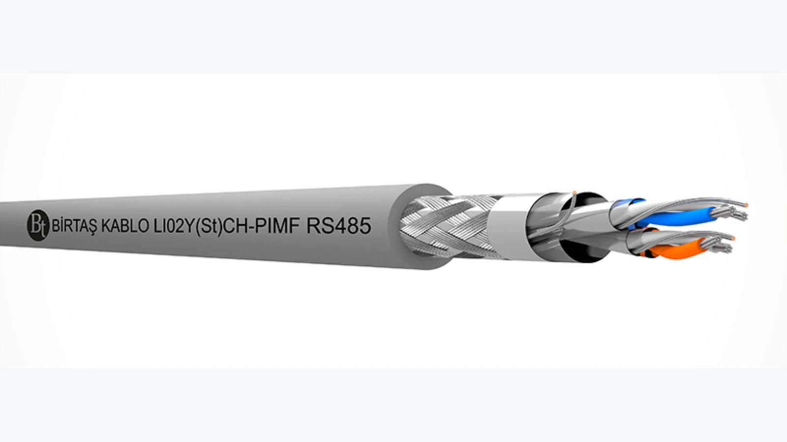
Birtaş Kablo’s LI02Y(St)CH-PIMF RS-485 product is described as a data-and-signal cable with PE insulation, halogen-free flame-retardant properties, and individual shielding layers. The pairs of wires are shielded using separate aluminum polyester tapes and tin-plated copper drain wires; the overall structure also includes additional aluminum polyester tapes, drain wires, and tin-plated copper braids. The HFFR outer sheath is designed for use in enclosed environments where low levels of corrosive gases and minimal smoke generation are required during fires. The manufacturer does not recommend this product for outdoor use or underground installations.
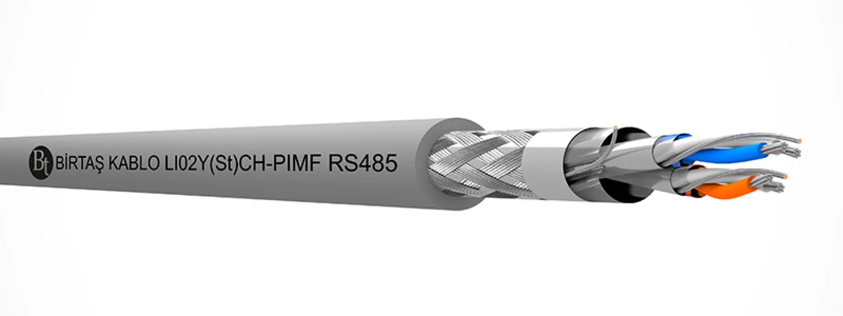
According to the official technical specifications, this cable features an impedance of 120 ±18 Ω at 1 MHz, a nominal mutual capacitance of 45 ±5 nF/km, and a maximum operating voltage of 300 V. The recommended operating temperature range is −30 to +80 °C, while the flexible application range is −5 to +70 °C. The minimum bending radius is specified as 7.5 × D for fixed applications and 15 × D for flexible applications. These parameters apply to the LI02Y(St)CH-PIMF RS-485 series; the term “flexible” does not imply continuous operation of the cable carrier. In cases where mobile applications are required, additional dynamic product testing must be conducted.
PIMF indicates that each pair is enclosed within a separate foil shield. This design helps reduce crosstalk between pairs, while the overall shielding provides additional protection against external interference. During termination, the two conductors belonging to the same pair must be handled together, and the pair twist must be maintained as close to the connector as possible. Drain wires and shielding layers must not be connected to any arbitrary signal terminals; instead, they must be routed in accordance with the shielding and grounding layout specified on the control panel and at the site.
Checklist for RS-485 field applications
- Protect the main line: Arrange the devices along the line as much as possible; avoid using long star connections.
- Verify the termination. Apply the termination resistors only at the necessary ends, in accordance with the instructions provided by the cable and device manufacturers.
- Plan signal biasing: Check whether fail-safe/bias resistors are present in the devices and verify that they can be managed through a centralized system.
- Maintain pair integrity: Place the A/B differential conductors in the same pair of twisted wires; do not separate the pairs arbitrarily.
- Limit branch length: If a T-shaped connection is required, minimize the length of the branch cable according to the data transmission speed and the device specifications.
- Manage voltage differences: Address the requirements for equipotential bonding and the reference conductor in system design.
- Verify the terminology: Check the pin diagram: manufacturers may use opposite A/B or +/− naming conventions.
CAT6 U/UTP: assess the complete channel performance
Birtaş Kablo’s CAT6 U/UTP 4×2×23 AWG PVC cable is a LAN cable with four balanced twisted pairs. The manufacturer provides a specification sheet on its product page, indicating a characteristic impedance of 100 Ω and a transmission performance up to 350 MHz. It is listed as a suitable option for applications such as Ethernet, Fast Ethernet, Gigabit Ethernet, PoE/PoE+, and others. The outer diameter of the cable is approximately 6.20 mm. It should be noted that these specifications apply to the specific product model and do not guarantee that any installed cable will automatically exhibit the same performance.
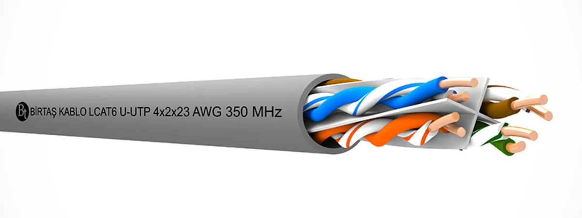
In an Ethernet channel, in addition to the horizontal cables, patch cables, keystone connectors or field connectors, panel assemblies, intermediate connections, and termination processes are also involved. Even the least performant component or a misinstalled part can limit the entire channel’s performance. Excessive untwisting of pairs at terminations, sharp bends, crushed cable connections, or deformation during pulling can disrupt the values of parameters such as NEXT, return loss, and attenuation. Commissioning tests should not only assess continuity but also verify that the channel or the permanent connections meet the required specifications for the intended application category.
In U/UTP cables, the pairs generally do not have additional foil or braided shielding. Interference-control measures such as balanced pair design, preserving the pair twist, clear routing, and consideration of the facility’s electromagnetic environment are essential for minimizing interference. For applications requiring long runs of high-power motor and drive cables, fast switching components within the control panel, or improper grounding, shielded cable options should also be considered. When selecting shielded cables, it is crucial that both the connectors and panel components maintain the integrity of the shielding.
PoE carries data and power in the same channel
When power is transmitted over Ethernet, the twisted pairs carry both data and electrical energy. Factors such as conductor resistance, line length, connector quality, bundle size, and ambient temperature can affect the level of heat generated. The presence of PoE/PoE+ application examples on the product page does not necessarily imply unlimited power transmission under all conditions. The standard of the active equipment, its power class, and the relevant cable variant specified by the manufacturer must all be taken into consideration when planning a project.
On a PoE line, incorrect or highly resistive terminations can cause local overheating. In cable management, it is important not to use excessively tight connections, ensure that cable bundles are well-ventilated, and pay attention to the fill level within the cable tray. The smaller cross-sectional area of patch cables also needs to be taken into account when calculating the total channel capacity. During acceptance testing, in addition to performing wire-map tests and checking high-frequency parameters, resistance imbalance checks required by power delivery standards should also be conducted in accordance with the project specifications.
Do not rely on similar names when selecting bus cables
Birtas Kablo offers a range of products for different industrial protocols in the BUS category. Not all data lines utilize the same impedance, number of conductors, sheath, or shielding. When selecting a cable for PROFIBUS, Interbus, CAN, KNX, or another system, it is essential to ensure that the physical layer standards of the device match those specified on the product page. It is not appropriate to adapt a BUS cable for a different protocol merely because its color or number of conductors is similar.
The topology of the line is also specific to the protocol. While some systems require a linear main line and end terminations, others support star or switched Ethernet architectures. The number of branches, couplers, repeaters, and maximum nodes cannot be determined independently of the type of cable chosen. During system commissioning, physical measurements, protocol diagnostics, and device error counters are all examined together.
Shielding and equipotential bonding
A cable shield ensures that parasitic currents flow along a controlled path. There is no universal rule regarding whether the shield should be connected at one or both ends; considerations such as the signal frequency, the facility’s grounding system, the potential difference, and the manufacturer’s instructions must be taken into account. A long, thin shield pigtail at high frequencies can result in high impedance; 360-degree termination is generally more effective for providing a smooth transition in most industrial applications.
If there is a difference in ground potential between different buildings or over long distances, simply disconnecting the shielding wire cannot resolve the issue. Equipotential conductors, galvanic isolation, fiber optic conversion, or appropriate overvoltage protection systems can be used to address this. The shielding wire is not intended as a protective ground conductor. Additionally, a drain wire can facilitate the connection of the shielding in a cable system, but it must not be treated as a power-carrying conductor.
Fire performance and installation environment
Products such as LIYCY or CAT6 cables with PVC insulation and RS-485 cables with HFFR insulation do not exhibit the same fire behavior. In enclosed public spaces where halogen-free materials and low smoke generation are required, tests are conducted to evaluate the product’s flame propagation characteristics, smoke density, and halogen emission levels. However, the designation “HFFR” does not imply automatic fire resistance or circuit integrity. For critical applications, additional requirements such as functional continuity and system certification may also be necessary.
Indoor products must not be installed outdoors, under UV radiation, in water, or directly in the ground. The use of cable trays does not necessarily ensure suitability for outdoor use; condensation and water accumulation may occur. For data cables to be used in moving machinery, their suitability regarding energy-chain use or resistance to torsion must be clearly verified. The term “flexible” may refer to ease of installation, but it does not guarantee a continuous-flex cycle life.
Installation and acceptance plan
The reel label and product code are compared with the drawings; the cable pulling force, minimum bend radius, and routing directions are determined before installation. To distinguish it from power lines, the intersection angles, metal tray divisions, and panel connections are implemented according to the project requirements. During termination, the twist of the cable pairs is preserved; the braiding and foil shielding are not damaged, and the connector is selected to match the cable diameter. Excess cable is not compressed into small rings.
During acceptance testing, for general signal cables, the continuity of conductors, short-circuit checks, insulation quality, and shield connections are verified; for RS-485, topology, termination, polarity, and communication error counters are inspected; for Ethernet cables, category certification is confirmed. Live system testing must include the most extreme conditions regarding load and interference. All measurement results are recorded along with the cable model, the port numbers at both ends, and the testing equipment used.
Information required for a quotation
- Protocol or signal type, data speed, frequency, analog range, and device interfaces.
- Topology, total length of lines, branch connections, number of nodes, and termination methods.
- Number of conductors or pairs, cross-section, characteristic impedance, capacitance, and category.
- Individual pair shields, overall foil/braid shield, and shield-earthing method
- Voltage, PoE power class (if applicable), loop resistance, and voltage drop limits.
- Fixed or dynamic installation, bend radius, tensile load, and cable-tray route
- Requirements for performance in indoor/outdoor environments, regarding temperature, oil, chemicals, UV radiation, water, and fire resistance.
- Requirements for connectors, panels, patch cables, cable glands, labels, testing standards, and reports.
Oskon evaluates Birtaş Kablo’s data and signal products not based on their type of cable, but rather on their end-to-end transmission capabilities. The LIYCY series offers general-purpose shielded signal cables, while LI02Y(St)CH-PIMF RS-485 cables are designed for differential communication, and the CAT6 U/UTP Ethernet cables provide different connection options. A reliable solution is only achievable when the product code, device requirements, installation route, termination methods, and acceptance tests are all carefully verified.
Official technical resources
- Birtaş Kablo – Data and Signal Cables
- Birtaş Kablo – Signal Cables
- Birtaş Kablo – LIYCY
- Birtaş Kablo – LI02Y(St)CH-PIMF RS-485
- Birtaş Kablo – Cat Cables
- Birtaş Kablo – CAT6 U/UTP 4×2×23 AWG PVC LAN Cable
Product specifications vary depending on the model and the latest manufacturer documentation. Before placing an order, it is necessary to confirm the exact product code, the physical characteristics of the device, the installation requirements, the applicable standards, any relevant certifications, and the availability of the product with the manufacturer.