Field wiring establishes the physical connection between sensors or actuators and the control system; however, the right solution goes beyond merely connecting the two ends. Factors such as the connector body, number of contacts, connection direction, conductor cross-section, cable outer diameter, as well as considerations related to temperature, movement, chemical exposure, and protection requirements must all be taken into account. Nemus’ official catalog lists M8 and M12 field-mount connectors, molded sensor cables, and various accessories that complete the connection process—these products are designed to meet the different needs of various applications. This guide explains which information should be collected in scenarios where the cable length needs to be determined in the field or where the connection must be re-established during maintenance. It is also important to verify the current availability of these products at the time of ordering.
What requirements do field wiring components address?
Pre-fabricated cable assemblies enable fast and repeatable connections in situations where standard lengths and factory-prepared ends are suitable. Field-mounted connectors, on the other hand, offer flexibility when the actual route is determined during commissioning, when the cable needs to pass through tight spaces, or when it is necessary to replace only the damaged end without replacing the entire cable. Accessories also play a role in protecting unused connection points and maintaining the integrity of the system. It is not appropriate to automatically choose one of these three options over another; instead, it is essential to determine in advance how many connections will be prepared in the field, which points will be frequently disassembled, and which installation methods the maintenance team will be able to use.
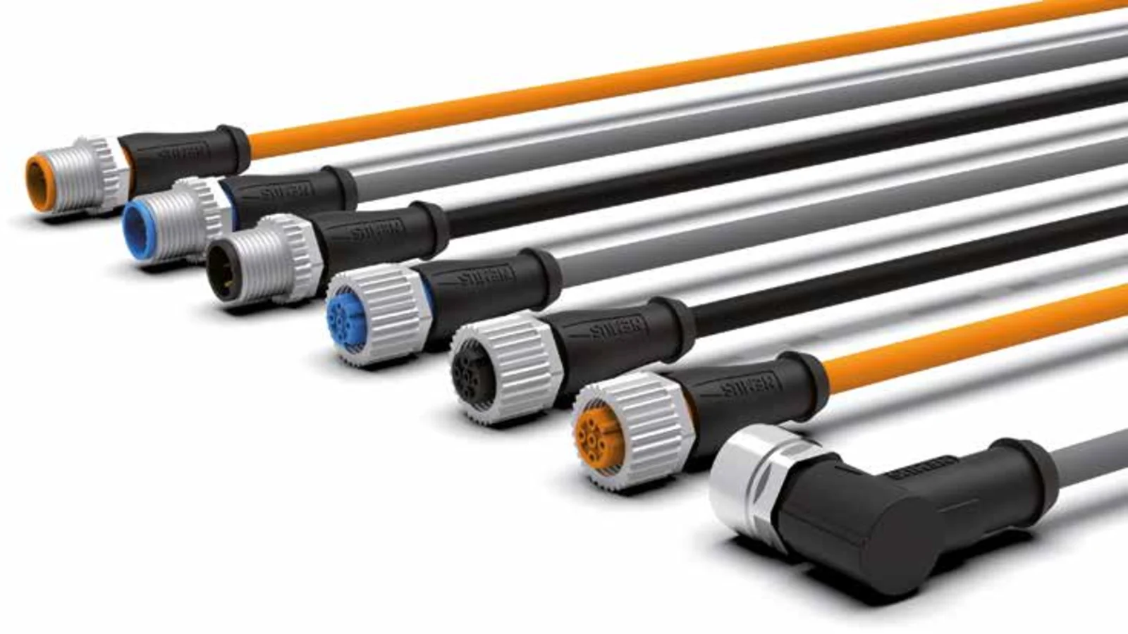
In the Nemus catalog, M12 field-mounted products are available in both male and female versions, as well as straight and 90-degree angled types, with options featuring three, four, or five contacts. The M8 series also offers male or female connectors, in straight or angled configurations, with three or four contacts. This diversity is not merely a matter of mechanical preference; the contact arrangement, pin assignments, and electrical specifications must all be compatible with the device for which they are intended. While straight outlet cables can be installed along the connection axis, angled outlets may require adjustments to fit within confined spaces. Nonetheless, the orientation of the angled connector housing must be chosen carefully to ensure that the cable can be routed without any strain after installation.
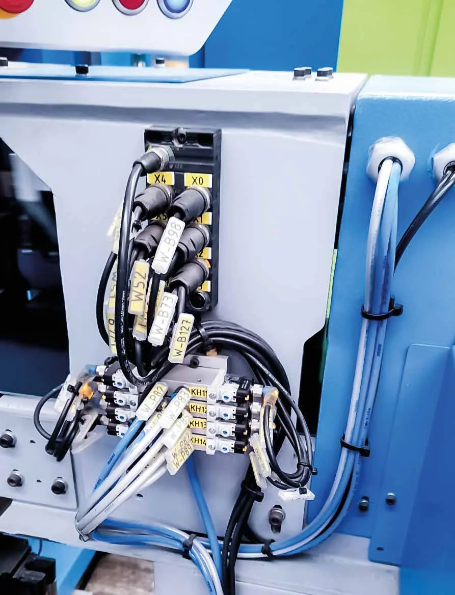
Selecting M12 field-assembled connectors
M12 is a commonly used body size in the field of automation for connecting sensors and actuators. In Nemus’ official catalog, the field-mounted M12 products available include models with three, four, or five contacts, identified by the code “A”. The catalog specifications indicate that the contacts are made of CuZn material with nickel/gold coatings, while the bodies are composed of PA66 reinforced with glass fiber, equipped with FKM sealing elements, and nickel-plated metal locking components. It is essential to verify these details using the specific product code before making a selection, as product revisions or changes in the connection design may result in variations in the technical specifications.
In the M12 field-mounting series, the catalog specifies that each contact is capable of handling a current of up to 4 A and has a conductor cross-section of no more than 0.75 mm². The outer diameter of the cable varies depending on the number of contacts and the specific product; for models with three or four contacts, the range is typically 4–6 mm, while some five-contact versions have an outer diameter of 4–8 mm. Therefore, the designation “suitable for M12 housings” alone is not sufficient. The cable’s outer diameter must fall within the specified range for clamping and sealing purposes, and the conductor cross-section must also meet the requirements of the terminal. Information regarding the insulation thickness, conductor preparation, and clamping torque should be obtained from the current installation instructions.
The voltage value should be read together with the number of contacts and the relevant product page. Instead of applying the general information in the catalog to all products, the current technical specifications of the selected product code should be used. For example, on Nemus’ current product page for a specific M12, five-contact, straight male field-mount connector, the reference DIN EN 61076-2-101, compliance with RoHS 2011/65/EU, and the information “number of installations >1,000 times” are listed. These details should not be presented as universal requirements for the entire field-mount connector family; instead, they should only be included in the specifications when the same product and revision have been confirmed.
Selecting M8 field-assembled connectors
M8 products offer significant advantages in more compact sensor and machine connections. The field-mounting series in Nemus’ catalog includes models with three or four contacts, as well as male and female versions, with both straight and 90-degree angled bodies. The catalog specifies maximum conductor cross-sections of up to 0.50 mm² and cable outer diameters ranging from 2.5 to 5 mm. For models with three or four contacts, the maximum operating voltage is 50 V AC or 60 V DC, with a current rating of 4 A per contact. The official catalog lists an operating temperature range of −25 to +85 °C. All these specifications must be confirmed by referring to the latest data sheet for the specific product model selected.
There is not only a difference in physical diameter between M8 and M12 connectors. It is impossible to simply match them based on their diameter without checking whether the male or female interface of the device to be connected matches, as well as the number of contacts and their pin arrangement. The front appearance of the socket on the machine and the mating surface of the cable connector must not be confused; the orientation in the drawings must always be carefully considered. In the order sheet, instead of simply stating “M8, four pins,” the gender, body orientation, coding, number of contacts, connection method, and cable specifications should all be specified in the same row.
| Selection criterion | M8 field assembly example | M12 field assembly example | Project checks |
|---|---|---|---|
| Contact option | 3 or 4 | 3, 4, or 5 | Device pin layout and signal functions |
| Body direction | Straight or 90° | Straight or 90° | Mounting clearance and cable outlet direction |
| Maximum cross-sectional area of the conductor | In the catalog, it is specified as 0.50 mm². | In the catalog, it is specified as 0.75 mm². | Selected product code and terminal configuration |
| Outer diameter of the cable | In the catalog, the size range is 2.5–5 mm. | Depending on the product, the dimension ranges from 4–6 mm; in some cases, it is 4–8 mm. | Sealing range and cable clamping range |
| Protection declaration | IP67 only when properly matched and securely fastened. | IP67 only when properly matched and securely fastened. | Counterpart, seal, torque, and installation requirements |
The IP rating applies to the complete connection
The IP67 rating specified in Nemus’s catalog tables applies to M8 and M12 field-mounted connectors when the connections have been properly made and secured. Similarly, for certain prefabricated M12 cable products, the IP65, IP66K, or IP67 ratings are also provided on the condition that the connections have been correctly established and tightened. It cannot be assumed that an exposed male or female terminal, a loosely secured locking nut, or a backseal closed with a cable of the incorrect diameter will provide the same level of protection. Protection requirements must be addressed at the system level; the device socket, the counterpart connector, the gasket, the outer diameter of the cable, and the entire installation process must all be verified to ensure adequate protection.
In facilities where there is washing, heavy dust, outdoor environments, or oil fumes, decisions should not be based solely on the IP code. Chemical compatibility, temperature cycles, mechanical impacts, vibrations, and the resistance of the cable sheath to the respective environment must also be considered. For high-pressure cleaning processes or the use of specific chemicals, the required compatibility must be clearly specified in the current manufacturer’s documentation for the selected product. Any resistance capability not mentioned in the catalog should not be assumed and included in the technical specifications, even if the application appears similar.
Specify sensor cables for the field conditions
Even if the right connector is selected, an incorrect cable design will limit the lifespan of the connection. In Nemus’ catalog, sensor cables are categorized under the headings PVC, PVC+, and PUR. The PVC option is designed for static applications; PVC+ is suitable for cost-effective, movable applications; PUR, on the other hand, is designed for applications requiring higher motion performance or in robotics. According to the general comparisons in the catalog: Under dynamic bending conditions with a bend radius of 10 times the cable outer diameter, PVC+ cables can withstand 3–5 million cycles, speeds of up to 180 m/min, and maximum accelerations of 10 m/s²; PUR cables can handle 4–6 million cycles, speeds of up to 240 m/min, and maximum accelerations of 30 m/s². These values represent the classification criteria under test and catalog conditions; the actual service life in practical applications depends on factors such as the application route, bending radius, torsion, load, and environmental conditions.
For PVC and PVC+, the catalog specifies general temperature ranges of –15 to +80 °C; for PUR, the range is –40 to +80 °C. PUR cables are also labeled as “halogen-free.” Just because a cable has a conductor/cable composition that is listed by UL or CSA does not mean that the entire finished connector assembly automatically qualifies for the same certifications. If a certification is required for a particular project, the manufacturer must be contacted to confirm the certification’s scope, file number, and relationship to the final product code. The specified temperature range should also be considered in conjunction with the product’s intended use (fixed or movable), the effects of oils, and the bundling conditions within the cable tray.
A practical field assembly workflow
- Describe the connection: Verify the M8 or M12 interface of the device, the male-to-female connection, the coding scheme, the number of contacts, and the pin functions according to the current drawings.
- Verify the cable. Determine the number of conductors, the cross-section, the outer diameter, the material of the sheath, the necessity for a shield, and the allowable bending radius.
- Select the body orientation: Decide whether the body should be straight or at a 90-degree angle, based on the service area and the natural direction of the cable outlet.
- Follow the installation instructions: For the stripping length, conductor preparation, terminal connection, back clamping, and locking torque, refer to the current manufacturer’s instructions.
- Conduct electrical tests: Record the continuity, pin matching, short-circuit checks, and any required insulation tests using an approved procedure.
- Perform mechanical control measures: Visually and using appropriate methods, confirm that the cable is securely fixed within the housing, the seal is in place, and the connection is tightly secured to the opposing component.
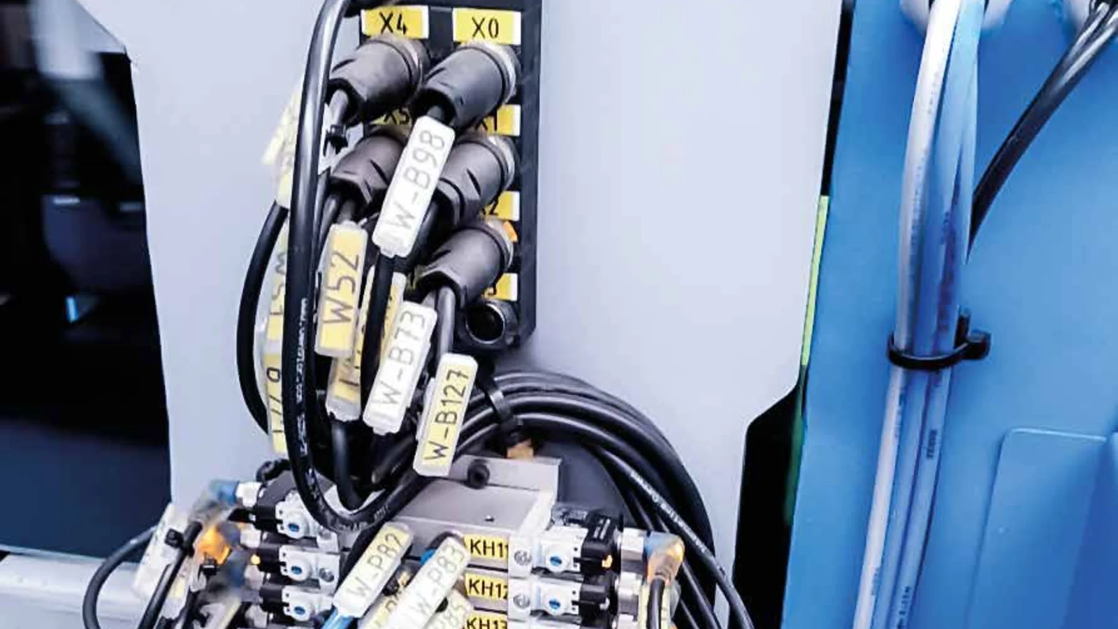
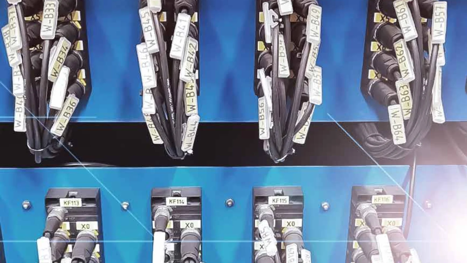
- Label it: Clearly display the cable number, start/end equipment information, and port details, if applicable, at both ends of the cable.
During this process, it is essential to avoid disconnecting by pulling on the cable instead of handling the connector body, applying excessive force when tightening it with a wrench, or forcing mismatched threads together. The maintenance instructions must specify the appropriate tools, tightening methods, and criteria for identifying damage. Incorrect pin connections may cause communication errors in some sensors, while in other circuits, they can lead to device damage or unexpected malfunctions. Therefore, testing the device before powering it on is a critical step.
Why protective caps and accessories matter
Unused machine ports, reserved for commissioning purposes, or terminals disconnected during maintenance can be exposed to the external environment. Nemus’ catalog offers dust caps for M12 female connectors, including tethered versions. The official catalog specifies that the material used is PA66 reinforced with glass fiber, meeting UL94 V0 standards; the connection size is M12×1 mm, and the temperature range is −45 to +90 °C. The IP67 rating depends on whether the cap is properly tightened. The type of cap to be selected should match the connector it is intended to protect. Where caps could be lost during production, consider the tethered version.
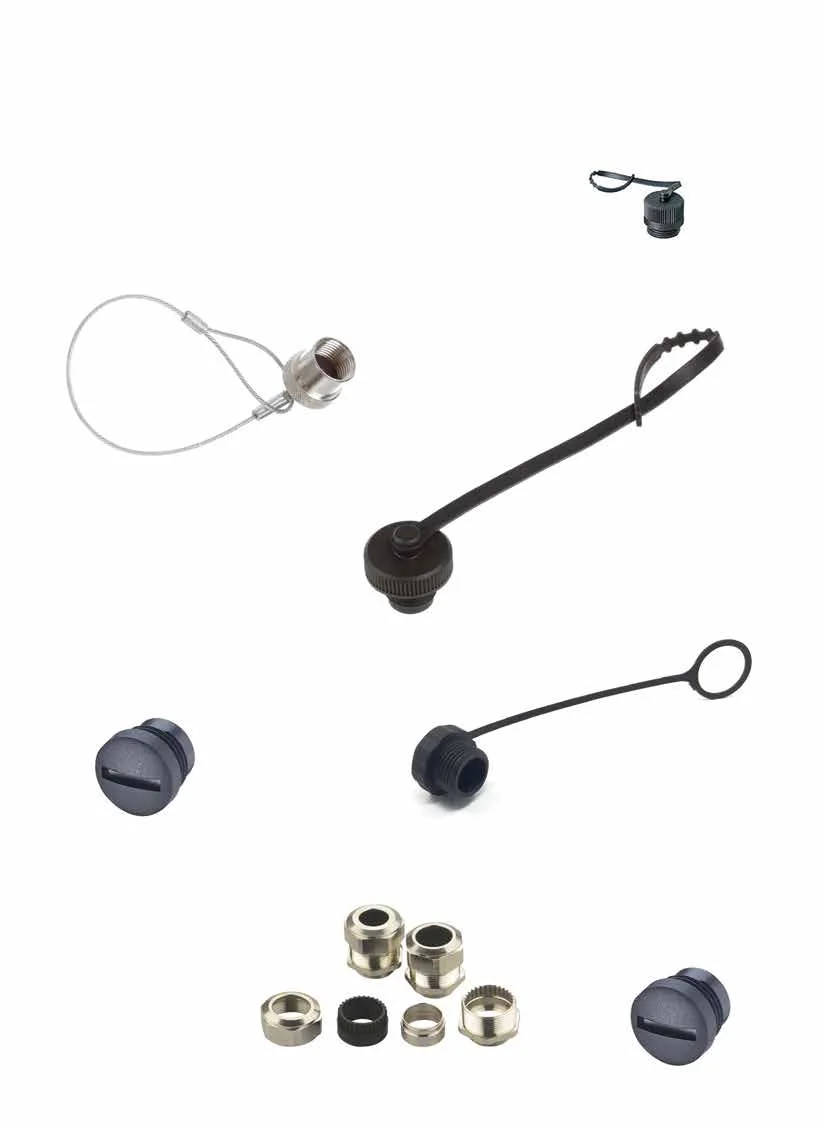
The list of accessories should be prepared not only for initial installation but also as a spare parts reference. Commonly used field-mounted male and female connectors, appropriate dust covers, and certified cable types should be kept in stock for critical circuits. However, products that appear similar may have different contact or pin configurations, which can lead to confusion. Storage labels should clearly indicate the full product code, connection diagram, and intended application; sealed components in opened packages must be protected from contamination.
In Nemus’s catalog, connection accessories also include T-adapters. The documented examples include an A-type connector with 5/5/5 contacts, connecting an M12 male connector to two M12 female connectors, as well as a distribution layout with 4/3/3 contacts, connecting an M12 male connector to two M8 female connectors. However, these geometries do not necessarily ensure that each signal is duplicated in the desired manner. The pin configuration and electrical distribution functions must be verified based on the schematic diagram of the specific product selected; adapters should not be incorporated into a circuit solely based on their number of bodies and contacts.
Commissioning and maintenance checks
In the commissioning documentation, keeping the cable list, pin layout, product codes used, routing details, test results, and photo records together facilitates easy comparison in case of future failures. For movable parts, it is essential to check the energy-chain fill, bending radius, and fixing points. Direct pulling or torsion forces should not be applied to the connectors. Even in fixed cables, sharp metal edges, hot surfaces, or constantly vibrating connection points can cause damage over time. The routing must be designed not only to fit during initial installation but also to accommodate all the machine’s movements and service positions.
During periodic inspections, factors such as loose locking mechanisms, cracked bodies, crushed cables, damaged seals, accumulation of oil or chemicals, and illegible labels should be checked. In the event of repeated terminal failures, it is not sufficient to simply replace the connector; the direction of output, cable fixation, as well as the bending and movement patterns must also be reevaluated. If a static PVC cable is used in a movable application, or if the specified cycle limits are exceeded, the root cause of the failure may be related to aspects beyond the product’s actual installation.
Field wiring list to prepare before requesting a quotation
- For each device, the interface options are M8/M12, along with specifications regarding coding, gender, number of contacts, and pin functions.
- Signal or supply voltage, contact current, and the required cross-sectional area of the conductor
- Cable outer diameter, core count, shielding requirement, and sheath type
- Fixed, repeated bending, drag chain, or robotic motion.
- Environmental conditions such as temperature, moisture, dust, oil, chemicals, UV radiation, vibration, and impact.
- The actual mounting space around the connector can be selected with either a straight or angled body design.
- Cable length, route, service allowance, labeling standard, and spare quantities
- Required test results, certification, documentation, and product revision information.
When all this information is provided in full, Nemus field-mounted connectors, sensor cables, and accessories cease to be merely a list of products; they become a viable connection system that can be put into use and maintained. In the end, the general product information available in the catalog serves as a starting point for making a decision. The current technical data sheet, installation instructions, and information regarding suitability for specific applications related to a particular product code must be confirmed with the manufacturer or an authorized partner before placing an order.