Sensor and actuator cabling transforms the numerous small connections within an automation system into a standardized and repeatable format. Issues often arise during commissioning when the wrong number of poles, coding, cable quality, or outlet direction are selected for a photoelectric sensor, proximity sensor, pressure switch, valve, or distributed I/O point. Phoenix Contact’s portfolio of sensor/actuator cables and connectors includes pre-assembled cables in various sizes, such as M8 and M12, open-end connections, double-ended cables, field-mounted connectors, distributors, and fast-locking M12 push-pull solutions.
This guide does not simply sort products based on their connector size alone. For a proper selection, various factors must be considered together, including the device’s connection layout, male or female interface, number of pins, coding system, whether the body is straight or angled, cable length, the need for a shield, whether the component is intended for fixed or movable applications, as well as factors related to oil and chemical exposure, temperature, vibration, and the desired protection class. Even two M12 connectors with the same appearance may have different coding systems or pin functions. Just because the physical shapes of two connectors match does not guarantee that they will provide the correct electrical signal distribution; it is essential to compare the actual product codes and the pin layouts of both devices.
Define the complete sensor/actuator connection
The selection of connection points begins with the device on-site, but does not end there. The M8 or M12 socket of the sensor, the port of the local distributor or I/O module, both ends of the cable, and the termination points on the control panel must all be clearly indicated on the same circuit diagram. A cable with one open end allows for a leak-proof connector to be pre-installed at the device during manufacturing, while the other end can be terminated at the terminal block or I/O module according to project specifications. For cables with both ends already connected to connectors, they can be easily inserted between two pre-installed ports to establish a specific connection. When using a distributor, it is also necessary to calculate the total current, the load per port, and the overall capacity of the main cable.
On the Phoenix Contact product page, signal and power cables are offered in various quality grades, covering applications ranging from standard machinery to robotics and conveyor systems, as well as outdoor environments and food and railway industries. However, this wide range does not mean that any M8 or M12 cable can be used in any situation. The cable material, shielding design, certifications, and bending and torsion specifications vary depending on the selected variant. For a robotics application, it is essential that the product description in the catalog explicitly states “for robots and conveyor systems,” and that the actual motion profile complies with the specified requirements.
Diameter is not the only criterion for M8 and M12 selection
M8 is an interface commonly used in sensors and in compact machine components where space for connections is limited. M12, on the other hand, has a much broader range of applications, supporting sensor/actuator signals, power supply, and industrial data transmission via various coding systems. While the “A” coding type is typically used for standard sensor/actuator connections, other coding schemes can be employed for different data or power transmission purposes. Therefore, simply stating “M12 cable” in a technical specification is insufficient. It is essential to specify the coding type, the number of pins, the male/female configuration, the contact side, the shielding type, the shape of the housing (straight or angled), and the locking mechanism in the same description.
As the number of poles increases, the number of signals that can be transmitted within the same connector body may also increase, but the nominal voltage and current ratings may change accordingly. While a three- or four-pole connection is sufficient for some sensors, other devices may require more contacts. Phoenix Contact offers a wide range of options in its signal and power cable portfolios, including connections ranging from M8 to M40, as well as 1/2 inch to 7/8 inch sizes. When selecting a connector for sensor/actuator applications, it is essential to refer to the specific standards of the device in question, rather than simply choosing the most common interface. In the event of using adapters or transition cables, the pin functions on both sides must be clearly matched according to the relevant diagrams.
Straight, angled, open-ended and double-ended cables
Connectors with straight bodies allow the cable to extend along the device’s axis; those with angled bodies can be routed along the contours of a narrow machine surface. However, it should not be assumed that angled types always require less space. When designing the three-dimensional layout, factors such as access to locking mechanisms by hand or with tools, the natural bending direction of the cable, the location of nearby sensors, and the presence of protective guards must all be taken into consideration. Making a sharp bend immediately after the cable exits the connector can bend the cable below its permitted minimum radius. On moving axes, the orientation of angled connectors must not induce torsion.
In open-ended cables, the color of the conductors serves merely as a supplementary identification; the precise function of each pin is determined by the current product drawings and device schematics. The type of cable gland used at the panel connection, as well as the type of shielding provided, are selected independently of the connector’s protection class. For double-ended cables, the combination of male-female connectors and straight sections at both ends is determined based on the application requirements. Pre-assembled cables can reduce installation time and ensure reliable connections; however, excessively long cables may pose new mechanical risks in moving areas. The optimal length of the cable should be determined by considering the actual route, service clearance requirements, and the range of motion involved.
PVC, PUR, shielding and motion profiles
PVC cables can be a suitable option for many standard applications; PUR cables, on the other hand, may exhibit different levels of performance in terms of movement, wear resistance, oil resistance, and chemical resistance, depending on the specific product variant. However, it is incorrect to interpret the material name alone as a direct indication of its technical specifications or resistance levels. The halogen-free composition, flame behavior, oil resistance, resistance to UV radiation, hydrolysis, microbial attack, and temperature range must be verified through the technical data of the respective cable type. For products to be used in cable systems, the minimum dynamic bending radius, allowable acceleration and speed, number of cycles, and any limitations regarding torsion must be carefully assessed in comparison with the specific requirements of the application.
Shielded cables are selected in those applications where the electromagnetic environment and the transmitted signals require it. Simply having the shield within the cable is not sufficient; a continuous and low-impedance shielding connection throughout the entire length of the cable, appropriate termination at the panel connections, and a proper system grounding scheme are also necessary. Phoenix Contact’s “Advanced Shielding Technology” is used for specific types of shielded products, focusing on providing reliable shielding in challenging environments. It should be noted that this feature is not inherent in all sensor cables; it is essential to verify both the shielding designation of the product and the shielding contact configuration of the counterpart device.
How to interpret a specific product example
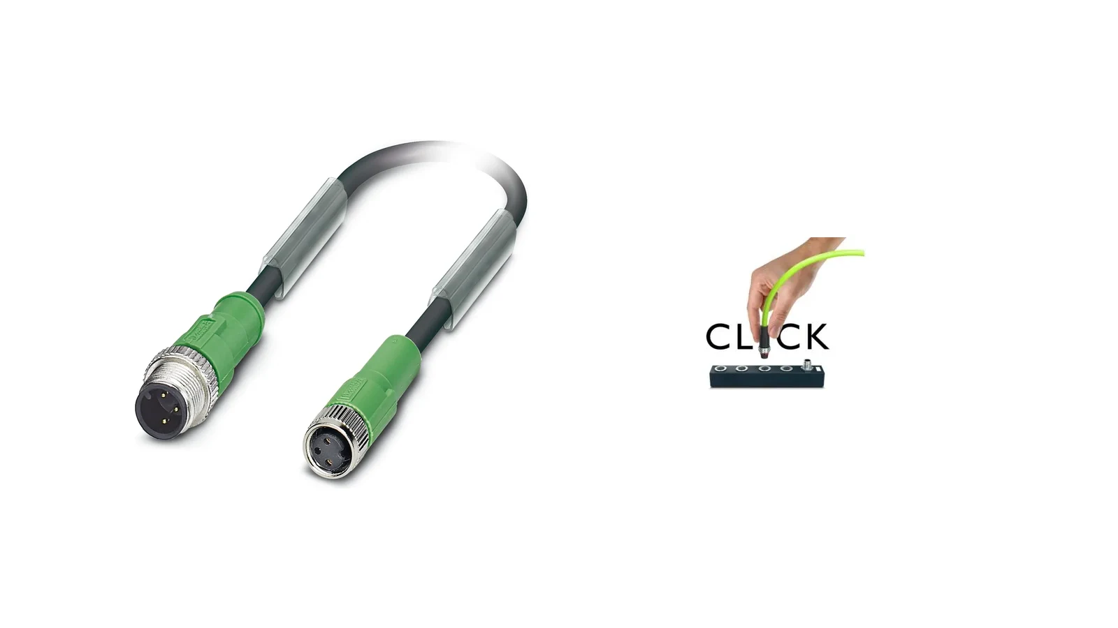
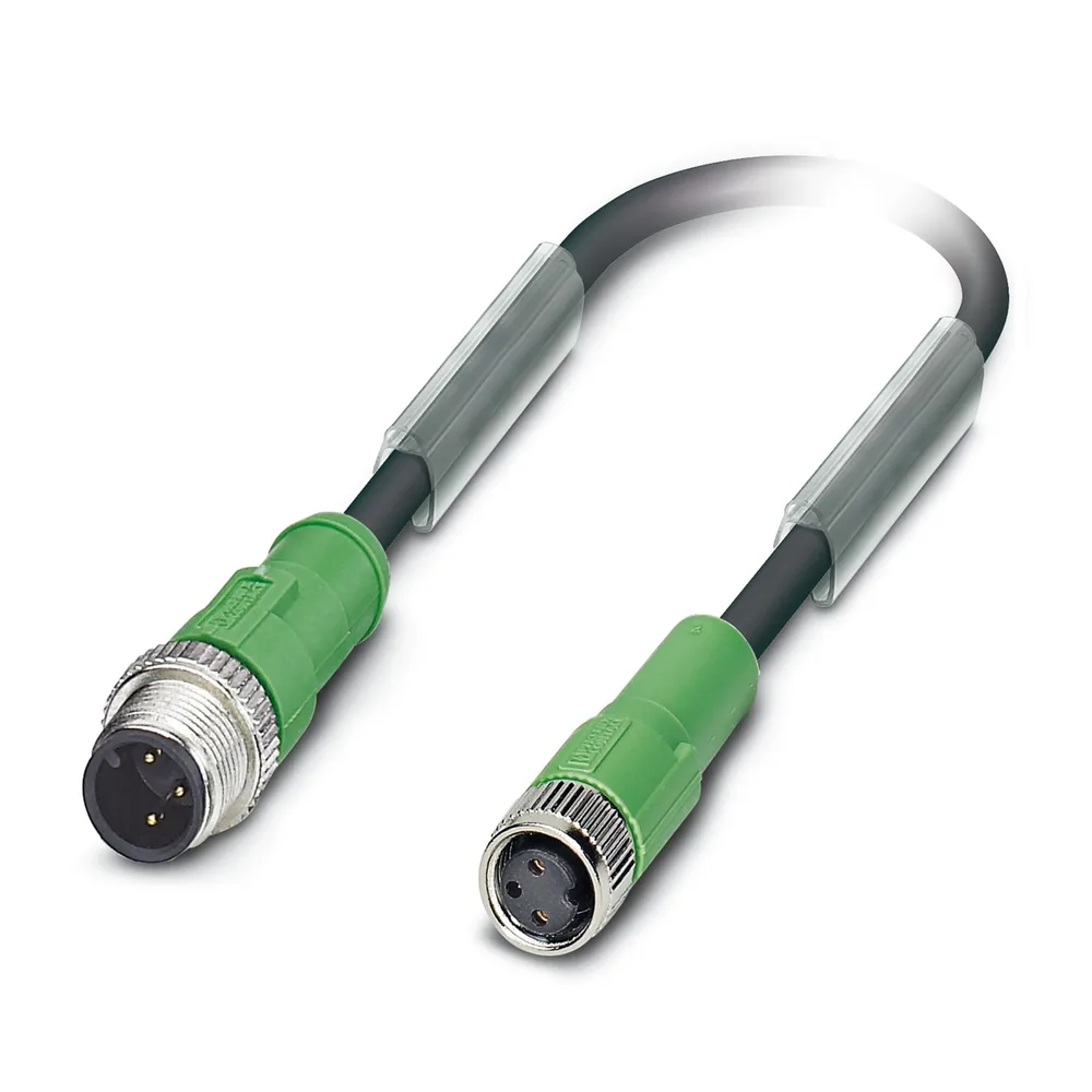
Phoenix Contact’s product page for the SAC-3P-M12MS/5,0-170/M8FS series provides a useful example of how the selection process is organized. This specific product is described as a sensor/actuator connection cable with three-pole A-coded connectors and a halogen-free PUR cable, measuring 5 meters in length and featuring a straight M12 male plug connecting to a straight M8 female socket. The page specifies nominal operating voltages of 48 V AC or 60 V DC, as well as a clamping torque of 0.4 Nm on the M12 side and 0.2 Nm on the M8 side. It is important to note that these values apply only to this particular model and its corresponding code and documentation version, and not to the entire SAC, M8, or M12 product portfolio.
On the same technical page, information such as the product’s IP65, IP67, and IP68 protection classes; IEC 61076-2-101 M12 and IEC 61076-2-104 M8 interface standards; a operating temperature range of -25 °C to +90 °C; and a minimum of 100 mating cycles is provided. The section on cables includes specific values regarding bending conditions, with a minimum bending radius of 18 mm for fixed installations and 36 mm for movable installations. These details illustrate how insufficient it is to describe a product simply as “5 meters of PUR cable.” The protection class should be assessed based on the correct assembly of compatible components and the tightening of the connection in accordance with the manufacturer’s instructions.
M12 push-pull differs from screw-locking M12
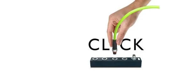
Phoenix Contact’s M12 push-pull system is designed for quick, tool-free locking in confined spaces and areas with high cable density. The portfolio includes device connectors, pre-assembled cables, field-mounted connectors, IP67 I/O devices, and IP67 power supplies. Both internal and external locking versions are available to accommodate various mechanical applications. The M12 Duo design provides flexibility in connecting M12 threaded connectors and push-pull connectors to specific device ports; however, this compatibility does not apply to all standard M12 ports. It is essential to verify that the counterpart port complies with IEC 61076-2-010 specifications and the selected locking mechanism.
The official Phoenix Contact website states that push-pull connections can reduce installation time by up to 80% compared to traditional threaded connections. This figure is dependent on the specific application, accessibility, and workflow; therefore, it should not be considered a fixed savings factor for every project. The eight-pin A-coded pre-assembled signal cables are available in various options, including male-to-female, straight-type, shielded, and unshielded versions, as well as IP65/IP67 protection ratings. The “Advanced Shielding Technology” refers to the shielded variants of these cables. In addition to the fast installation time, other important factors include correct port selection, visual and physical verification of secure connections, and proper maintenance procedures.
When should a field-assembled connector be selected?
Pre-assembled cables offer the advantages of pre-established connector-cable connections and fixed lengths. Field-installable connectors, on the other hand, provide flexibility in situations where the cable length needs to be determined during installation, or where existing cables need to be terminated or repaired. Phoenix Contact’s push-pull portfolio includes unassembled options with Push-Lock connections suitable for tool-free field wiring. However, the acceptable cable outer diameter, conductor cross-section, shielding type, stripping length, and connection technology depend on the specific product code.
During field installation, the sequence of installing seals and clamping components, the preparation of the cable sheath, the alignment of the contact surfaces, and the proper seating of the conductors must be carried out in accordance with the manufacturer’s instructions. It cannot be assumed that a connector that can be mechanically closed with any type of cable will provide the desired IP rating. The outer diameter of the cable must comply with the required sealing specifications; the sheath must be intact and in good condition; and no tensile forces should be transmitted to the contacts. Before commissioning, tests for pin-to-pin continuity, short-circuit checks, contact continuity, polarity, and functionality must be conducted; the field installation process must also be documented.
| Selection criterion | Main options | Verification point |
|---|---|---|
| Interface | M8, M12, and other circular sizes | Mating-port standard, coding, pole count, and male/female configuration |
| Body and terminal configuration | Straight, angled, open-ended, or double-sided. | Mounting area, service accessibility, pin alignment, and actual cable routing. |
| Cable structure | PVC, PUR; variants with or without shielding. | Motion, temperature, oil and chemical effects, EMC, and required certifications. |
| Locking | M8/M12 threaded or M12 push-pull connectors | Compliant port geometry, in accordance with the relevant IEC standard, and proper installation procedures. |
| Installation method | Preassembled cable or field-assembled connector | Cable outer diameter, conductor cross-section, shield termination, and test plan. |
| Environmental protection | IP classes based on product code | The connection has been properly made using a matching, fully locked/plugged cable. |
Quotation and site survey checklist
- Record the device connections: Specify the port dimensions, coding, number of poles, male-female configuration, and pin functions as indicated by the manufacturer.
- Define the endpoints separately: Specify whether the body at both ends is flat or angled, whether it features a threaded or push-pull locking mechanism, and whether open-end terminations are required.
- Verify the electrical data: Verify voltage, continuous and peak current, shielding requirements, and the lowest-rated component in the connection.
- Measure motion: Describe it in terms of fixed positions, drag chains, robotic rotations, or intermittent movements; also include expectations regarding stroke length, speed, acceleration, and cycle time.
- Describe the environment: Consider factors such as temperature, oil, chemicals, UV exposure, washing, vibration, impact, and industry-specific certifications when selecting the right product.
- The length should be determined based on the actual route. Maintain the bending radius and clearance at the connector outlet; avoid any uncontrolled bends in the cable.
- Complete the protection chain: Protect unused ports with appropriate covers; ensure that the connector, the corresponding port, the cable, and the panel socket are all properly connected.
- Create a test and labeling plan: Record the pin continuity, polarity, short-circuit tests, shielding, mechanical lock status, and functional tests on the connection label.
Oskon matches Phoenix Contact sensor/actuator cables not only based on similar product images in the catalog but also by considering the machine’s I/O configuration and mechanical layout. The right connector is one that meets the device’s port requirements, signal function, routing, motion profile, and maintenance considerations simultaneously. The final order code must be confirmed in conjunction with Phoenix Contact’s current product page, technical drawings, installation instructions, certification information, and documentation for the counterpart device.