In conveyor automation, the main challenge lies not so much in the number of motors used, but rather in the amount of power, commands, sensors, and identification data that need to be transmitted to each driving point. Bihl+Wiedemann’s drive portfolio based on the AS-Interface standard integrates various functions within the same field architecture—ranging from simple binary movements to cyclic speed control and ramp adjustments, as well as from motorized rollers to frequency inverters. This guide is designed to help you properly allocate tasks between ASi-3 and ASi-5 protocols, select the most suitable drive interface according to your actual process requirements, and divide long conveyor lines into manageable sections that can be easily integrated into the system.
Start conveyor projects with the control task before the motor list
Not all motors located on the same line have the same data requirements. On a conveyor belt, simple start/stop commands and a ready signal may be sufficient. On a sorter, functionality such as direction change, two speeds, or several fixed operating modes may be necessary. In a section that handles sensitive products, it might be essential to periodically adjust the speed, as well as the acceleration and deceleration profiles, and to transmit motor parameters like current or temperature to the higher-level controller. Implementing comprehensive communication for every device increases investment and engineering complexity; whereas reducing all communication to just binary signals limits the visibility of the overall process.
Therefore, the first document should not be a product list, but rather a drive matrix. Each row in this matrix specifies the motor type, supply voltage, power class, local sensors, commands, feedback signals, safety responses, target cycle times, and the device’s behavior in the event of a fault. By making the selection between ASi-3 and ASi-5 based on this matrix, it is possible to use both technologies together in the same application without any unnecessary redundancy.
ASi-3 and ASi-5: different tasks on the same cable
Bihl+Wiedemann’s current drive solution page clearly states that ASi-3 and ASi-5 devices can be used together in the same application via combined ASi-5/ASi-3 gateways. Although the technologies are different and each requires its own master function, they can still operate together over the same yellow ASi profile cable. This distinction is important: the term “compatible” does not mean that an ASi-3 device can be converted into an ASi-5 device; rather, it means that the gateway is capable of managing both generations within the same field configuration.
| Requirement | ASi-3 approach | ASi-5 approach | Project decision |
|---|---|---|---|
| Simple drive commands | An economical solution for dual functions such as “on/off”, “right/left”, or “open/close”. | Feasible, but perhaps overly comprehensive for a dual-purpose application only. | Compare the actual number of I/O ports with the total number of connections. |
| Speed and ramp | Command structure that is limited and depends on the product and pin configuration. | In appropriate motor modules, the speed and acceleration values are programmed in a cyclic manner. | Verify the compatibility of the drive by completing the full product registration process. |
| Serial interface | Focused on binary field control | CANopen, RS485, or Modbus TCP communication, depending on the product selection. | Instead of saying “It supports ASi-5”, simply list the selected module-interface combination. |
| Diagnostics | Basic status and dual-error information | More detailed data specific to the channel and drive. | Specify the scope of PLC labels, alarm messages, and maintenance screens. |
| IO-Link | It is not directly aimed at achieving next-generation integration. | Integration with IO-Link master solutions via ASi-5. | Verify the port class, data length, and device parameters. |
According to the official drive application notes for ASi-5, it is stated that process data from multiple motors can be transmitted with a cycle time of 1.27 milliseconds when properly configured. However, this cycle time does not constitute a fixed, project-guaranteed value that remains unchanged regardless of the number of devices or the length of the data. The actual value must be determined based on the number of connected nodes, the amount of process data per node, and the configuration of the gateway. Instead of using a generic “product family” slogan in the design documentation, a precise network configuration should be provided.
Yellow profile cable offers more than cable savings
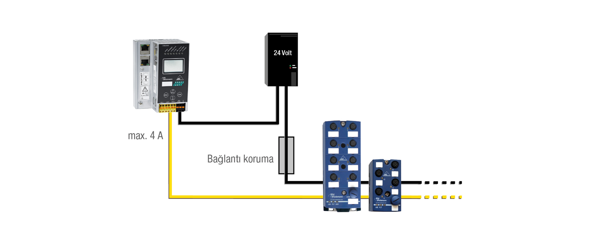
In the AS-Interface approach, data and ASi control signals are transmitted via profiled cables, which feature a geometry that ensures mechanical protection against reverse polarity. The piercing connection technology enables the module to be connected to the profiled cable without the need for intermediate connectors or pre-fabricated branch cables. Topologies such as line, star, or tree structures facilitate the establishment of a field layout that closely matches the physical arrangement of the conveyor. For actuators that require auxiliary power, a separate AUX line is provided; however, the convenience offered by the data cable does not replace the necessity of proper motor power calculations.
The route of the profile cable is determined with consideration of mechanical impacts, bending, module accessibility, and any additional areas that may need to be added later. It is essential to ensure that the drilling point is correctly aligned with the base module and that the manufacturer’s guidelines for clamping and installation are followed. The network configuration, including parameters such as line length, repeaters, and terminations, must be compatible with the selected gateway and topology. The length of a conveyor, measured in meters, does not correspond directly to the electrical length of an ASi segment; large facilities are typically divided into manageable network segments.
Managing zone density with cable-duct motor modules
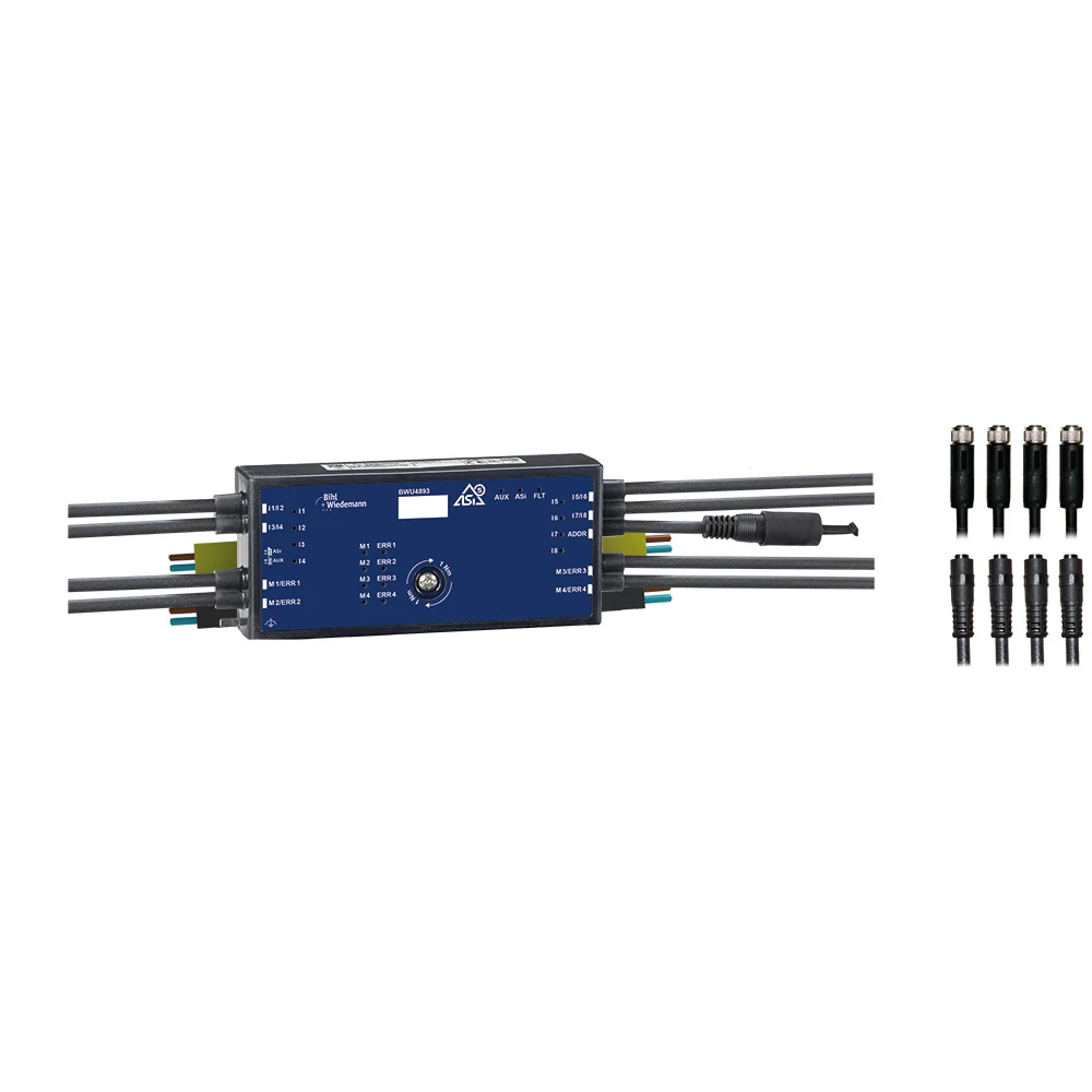
On long conveyor systems, the physical design of a module is just as important as its electrical specifications. For example, the BWU4893 is a flat motor module that complies with ASi-5 standards, features IP54 protection, and, according to the product page, can be installed in cable channels with a minimum depth of 30 mm. However, the group data page dated January 14, 2026, specifies a minimum channel depth of 19 mm and a body depth of 28 mm. Due to this discrepancy in the manufacturer’s documentation, the installation dimensions must be confirmed prior to ordering by referring to the latest dimension drawings and the manufacturer’s confirmations. The official product data includes information such as four M8 motor connections for the four 24-V motorized rollers, eight digital sensor inputs, motor power supply via the AUX interface, and a single ASi-5 address. The detailed 7-A slow fuse information for each motor circuit is also part of this complete product specification.
This design allows the motor and sensor connections for the four conveying zones to be concentrated along the conveyor body. However, the IP54 classification is not considered sufficient for environments with frequent cleaning, exposure to the open air, or high dust levels. Motor compatibility, connection pins, cable lengths, and current ratings are determined depending on the product variant. The fact that all four drives are housed within a single module also increases the potential for failure; therefore, maintenance strategies must take into account module replacement, zone shutdown procedures, and access to spare parts.
Zero-pressure accumulation (ZPA): link zone logic to the mechanics
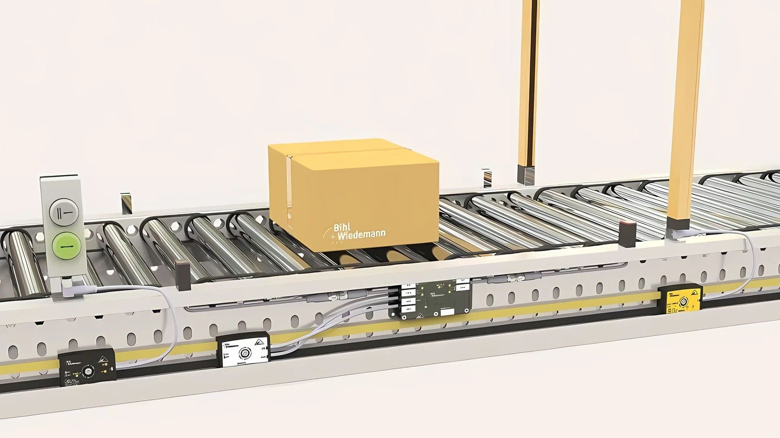
Zero-pressure accumulation, or ZPA, enables products to move between zones without exerting a continuous pushing force on each other during the buffering process. A sensor signals the entry of a product into a zone, and the control logic activates the motor based on whether the next zone is ready for processing. Bihl+Wiedemann states that with certain ASi-5/ASi-3 gateways, multiple zones can be configured using the ZPA function without the need to write separate PLC programs for each zone. However, this does not mean that the conveyor system automatically adjusts its operation to suit each individual product.
Product length, sensor position, roller spacing, friction, slope and stopping distance determine zone geometry. For boxes with a high center of gravity, verify ramp settings together with mechanical guidance. Mixed product lengths may require dual-sensor coverage or recipe logic. ZPA is a conveying function that depends on suitable mechanics, detection and parameters.
Matching motorised roller brands and modules
The area where drive control based on the AS-Interface standard is most widely used is in 24 V and 48 V motorized rollers. Bihl+Wiedemann motor modules can be directly connected to these rollers without the need for an external control unit. Currently, there are module-specific solutions available for drive units belonging to the Interroll, Itoh Denki, SEW, Pulseroller, Rulmeca, and Rollex product families. The selection of the appropriate module depends on factors such as the motor brand and type, as well as the required supply voltage, cycle frequency, and the number of sensors the module needs to accommodate.
On the ASi-5 side, the BWU4246 controls two 24-V (20/35 W) motorized rollers, while the BWU4212 controls two 48-V (20/35/50 W) roller. Both modules use 2 × 16-bit cyclic data to set speeds and acceleration profiles, and read information on motor current, as well as on parameters such as overheat, overvoltage, short circuit, and supply voltage. They are equipped with internal fuses (4 A for the BWU4212 and 5 A for the BWU4246) and four additional digital inputs. The speed and rotation direction of each roller can be independently adjusted within a cycle time of 1.27 ms. With a dual-line ASi-5 gateway, 248 motorized rollers and 496 digital inputs can be managed over a distance of up to 400 meters using a single IP address.
ASi-3 cable-duct and IP67 motor modules support units including Interroll EC5000 AI and EC310 AI, Itoh Denki PM500/PM605 ME/XE/XP and CBM-105, Rulmeca RDR BL-2 and Rollex Type 840. Speed is selected through analog parameters as 6 or 8 fixed steps, depending on product. Each motor provides fault diagnostics and has a 3.5 A internal fuse. An ASi-3 line up to 1200 m collects 248 motors and 248 or 496 digital inputs through one gateway. For products with their own controllers, such as SEW ECC-DBC and Pulseroller E-Qube, modules carry the binary interface: an ASi-3 digital module controls one unit and an ASi-5 digital module two units.
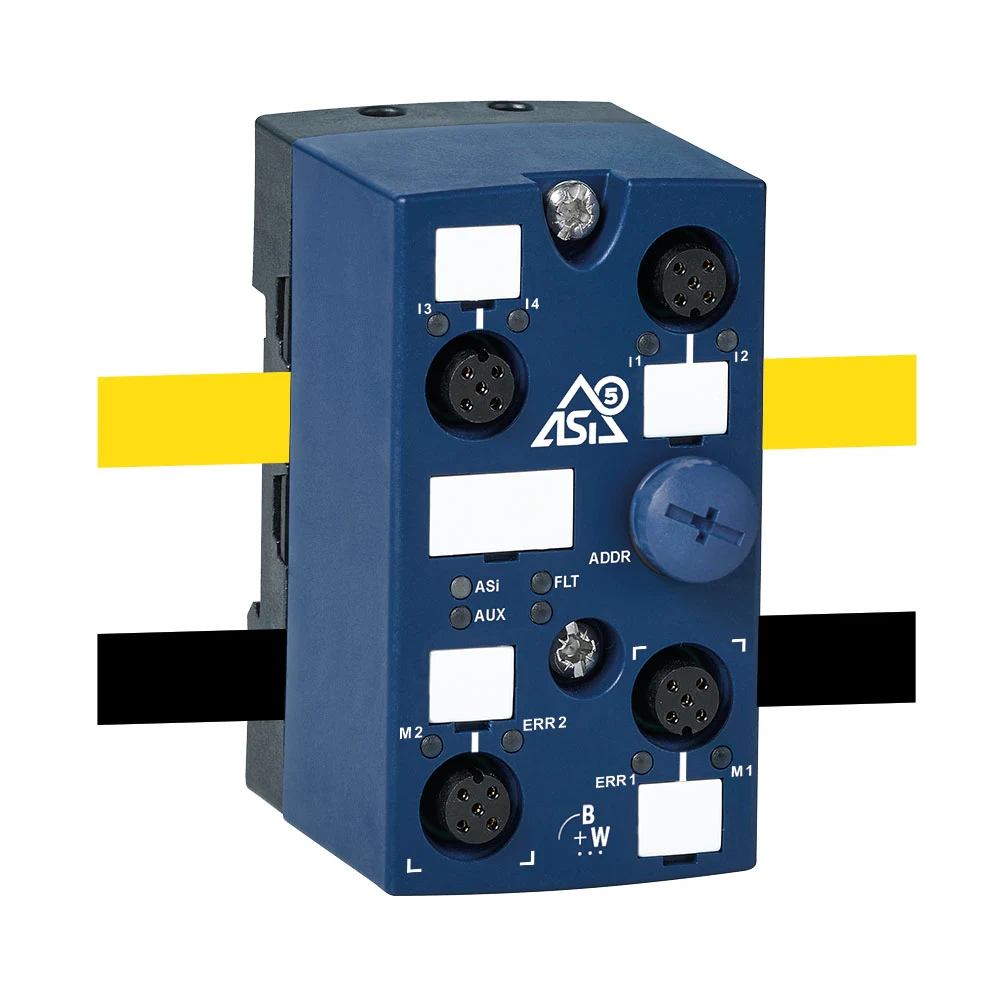
The practical reason for choosing distributed motor modules over a central multiple-control unit lies in the scope of potential failures. When a unit that integrates four motors and four sensors in a single enclosure malfunctions, the entire equipment is rendered inoperable. However, in the case of AS-i motor modules, the affected area is limited to just two motors, allowing the rest of the line to continue functioning. Additionally, the requirement for a linear topology and pre-calculated cable lengths, which are essential in Ethernet-based systems, does not apply here. The module can be simply attached to the desired location using a screw-on connection, and its position can be adjusted later on if necessary.
Power distribution and 24 V sensor supply on 48 V roller lines
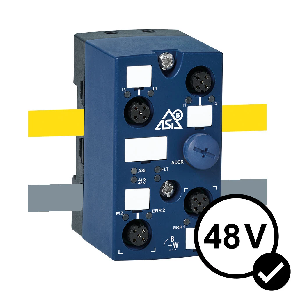
On long and heavily used conveyor lines, 48-V motorized rollers mean twice the power at the same current level – resulting in direct energy savings in terms of power consumption and losses. Units of 20 W, 35 W, and 50 W can operate on the same line, and 24-V and 48-V rollers can be used together. Since the speed and acceleration of each motor can be individually adjusted, factors such as the weight, size, position of the conveyed items, and the risk of them tipping over can be taken into account on a zone-by-zone basis. A separate gray profile cable is used for 48-V power supply.
When a 48 V line needs 24 V sensors or actuators at a few locations, voltage converters can avoid a second 24 V AUX cable throughout the system. BWU4249 provides ASi and 24 V AUX through M12, BWU4250 provides only 24 V AUX through M12, and BWU4248 uses profile cable. All have short-circuit protection, supply 1 A and attach directly to 48 V AUX profile cable through piercing connections. Converter cost can be offset by removing additional black cable and a cabinet 24 V supply.
ASi-3 for basic frequency inverter control
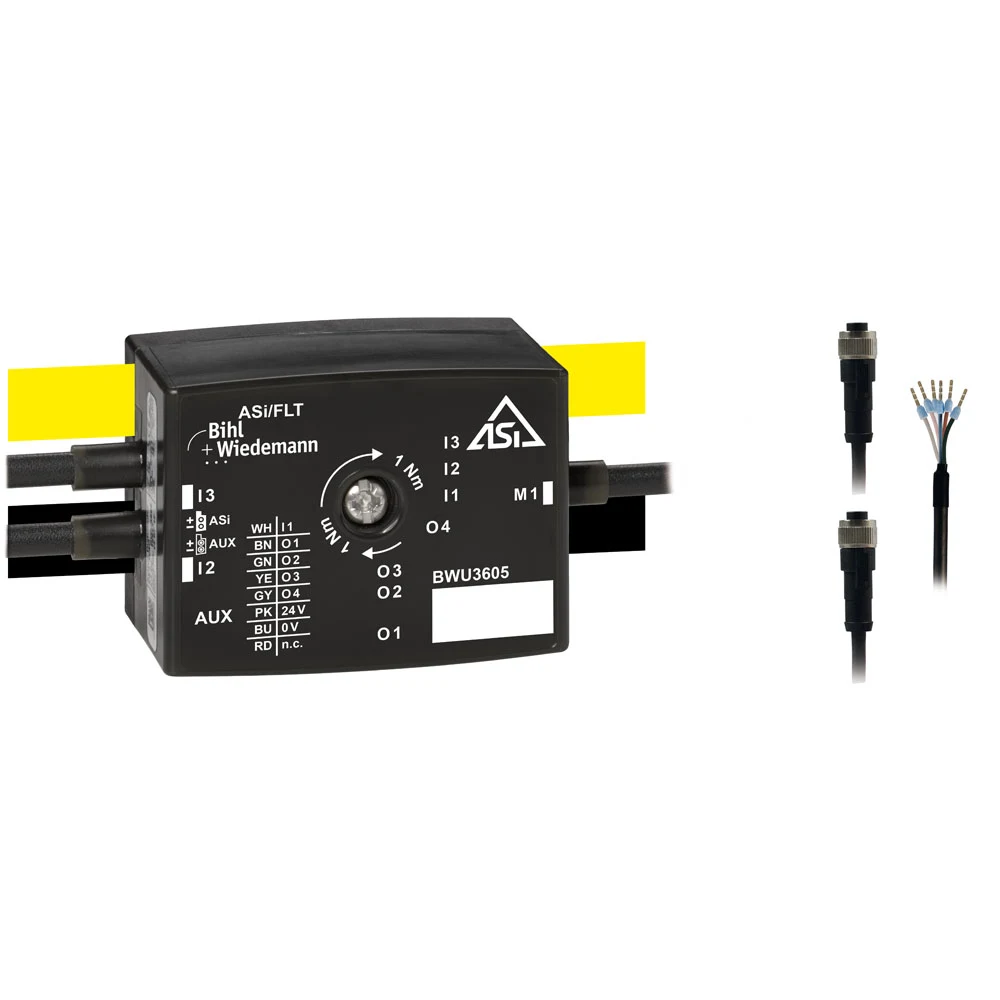
Not every frequency inverter requires cyclic parameter exchange. ASi-3 may be simpler for start/stop, direction and a few fixed states. BWU3605 is an IP67 active-distributor motor module for binary-controlled frequency inverters. The product description lists two digital inputs, motor control and sensor supply through AUX, one round-cable connection, two M12 sockets and one AB address. each cable and connection arrangement supports field integration with specific drives.
The term “frequency inverter control” should be used with caution here. The ASi module does not act as an inverter that supplies power to the AC motor; rather, it transfers the command and feedback signals from the inverter to the ASi network. The power supply circuit, motor cable, protective components, thermal considerations, EMC requirements, and safety functions of the drive remain part of the drive’s own electrical design. It is essential to ensure that the correspondence between the commands sent via the digital interface and the corresponding pins is clearly specified in both the module’s and the drive’s documentation.
ASi-5 when serial drive data is required
When it is necessary to obtain information such as speed, acceleration, status, perform drive diagnosis, or transfer parameters, using the drive’s communication interface is often more practical than increasing the number of binary I/O ports. Bihl+Wiedemann’s ASi-5 drive portfolio offers serial or Ethernet-based interfaces such as CANopen, RS485, and Modbus TCP, which are integrated into the motor modules specific to each product. Not all of these interfaces are available in every motor module. The selection of the appropriate drive should be based on factors such as the drive manufacturer, the drive family, the available interfaces, and the required data capabilities.
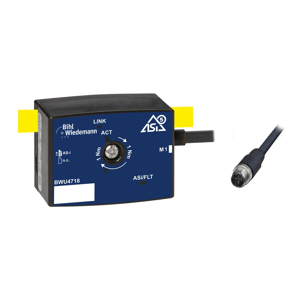
BWU4718 is an ASi-5 active distributor for connecting a SEW MOVI-C frequency inverter through Modbus TCP. The official record specifies IP67, a 35 mm housing depth, a D-coded four-pole M12 connection, a one-meter cable and one ASi-5 address. This is a drive-specific interface module; it does not mean every ASi-5 module has a Modbus TCP port.
Controlling decentralised AC motor drives with ASi
In conveyor systems, where motorized coils are insufficient at certain points, motor-mounted or field-mounted AC drives come into play. The decentralized drives from SEW, Lenze, and NORD can be controlled using the same yellow cable as the Bihl+Wiedemann modules specific to each product. This enables the management of dozens of drives via a single gateway address, rather than requiring over 100 individual IP addresses.
The SEW MOVIMOT series is driven by the ASi-5 IP67 motor module BWU4068. This module provides the drive with 3 × 16-bit process output data (control word, speed reference in percentage, and ramp function), and reads back status information, current value, and additional status signals from the drive. It also features four digital inputs and two digital outputs. The cyclic data format is compatible with SEW’s PROFINET communication protocol, allowing most existing drive control programs written for PLCs to be reused. With the use of a dual-line gateway, up to 124 MOVIMOT units over a distance of 400 meters can be managed via a single IP address, providing 496 digital inputs and 248 digital outputs. For simpler applications, the SEW MLK30A (with f1/f2 fixed speeds set via DIP switches and supporting only one ASi slave) and MLK31A (with six fixed speeds and analog slave functionality) can be used over the ASi-3 protocol; in these cases, up to 62 drives and 124 digital inputs can be controlled over a distance of 1200 meters.
The Lenze i550 Protec field-mounted drive is connected via the ASi-5 IP67 IO-Link master modules (BWU4067 and BWU4088). Basic parameters such as speed and torque commands, digital/analog output controls, and ramp functions are programmed in the 12-byte process data field. In return, the drive reports status information, speed, torque, current levels, and any error codes. Thanks to IO-Link’s data storage capability, these parameters are retained on the master module and automatically transferred to the new drive during replacement—eliminating the need for manual parameter setting during commissioning or service operations. With this configuration, up to 124 drives and 868 digital inputs can be managed over a distance of 400 meters. For drives designed specifically for conveyors, such as the Lenze Smart Motor and NORD SK180E, the ASi-5-configurable IO module BWU4232 is used. The Smart Motor offers five fixed-speed settings via three digital outputs, while the SK180E provides two fixed-speed options via two digital outputs. Error codes are read from the digital inputs, and speed and ramp values are programmed using the manufacturer’s own software (NFC or NORDCON). The wall-mounted or motor-mounted Lenze 8400 Motec and NORD SK270E NORDAC Link units also offer variable speed control and STO functionality, leveraging their analog ASi slave functionality.
The common benefit of these three approaches is the same: on a single communication line, motor control signals, as well as safety, analog, and IO-Link signals, are transmitted; a free-form topology can be established; drive and module failures can be diagnosed via the gateway; and drive and I/O tests can be performed without the need for a PLC. Additionally, the drive’s power supply circuit, motor cable, protective components, and EMC design remain within the scope of the respective electrical project in all circumstances.
A brief overview of drive solutions
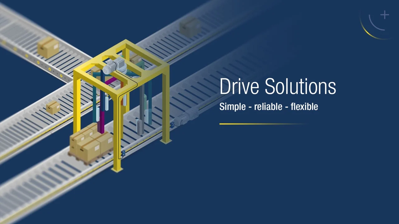
The following official Bihl+Wiedemann video outlines the scope of drive solutions available using ASi-3 and ASi-5 protocols, and demonstrates how various components—from motorized rollers to frequency inverters—can be integrated within the same field infrastructure.
Passive Safety: stopping drive groups through one safe output
In traditional field solutions, a separate safety output is required for each actuator. However, on conveyors, it is often sufficient to safely disable groups of drives simultaneously. In the Passive Safety approach, control signals are transmitted via the yellow ASi cable, while power is supplied via the black AUX cable. By safely cutting off the AUX power supply, all drives within that group are deactivated at the SIL 3/PL e safety level. Achieving the same safety level using the traditional round-cable architecture is significantly more costly.
This distinction has significant operational implications: When the AUX connection is interrupted, the yellow cable continues to provide power, allowing sensor data to be read. However, the modules report to the gateway that the AUX voltage is lost. In Ethernet-based distributed I/O systems, communication with modules that have lost power is also interrupted, resulting in the loss of status information. Since the yellow ASi cable can carry currents of up to 8 A and the black AUX cable up to 20 A, the power distribution is more cost-effective per meter compared to typical M12 round-cable solutions. Safety measures can be implemented locally within the control panel using IP20 modules or in the field using IP67 modules.
Gateways, field networks and data models
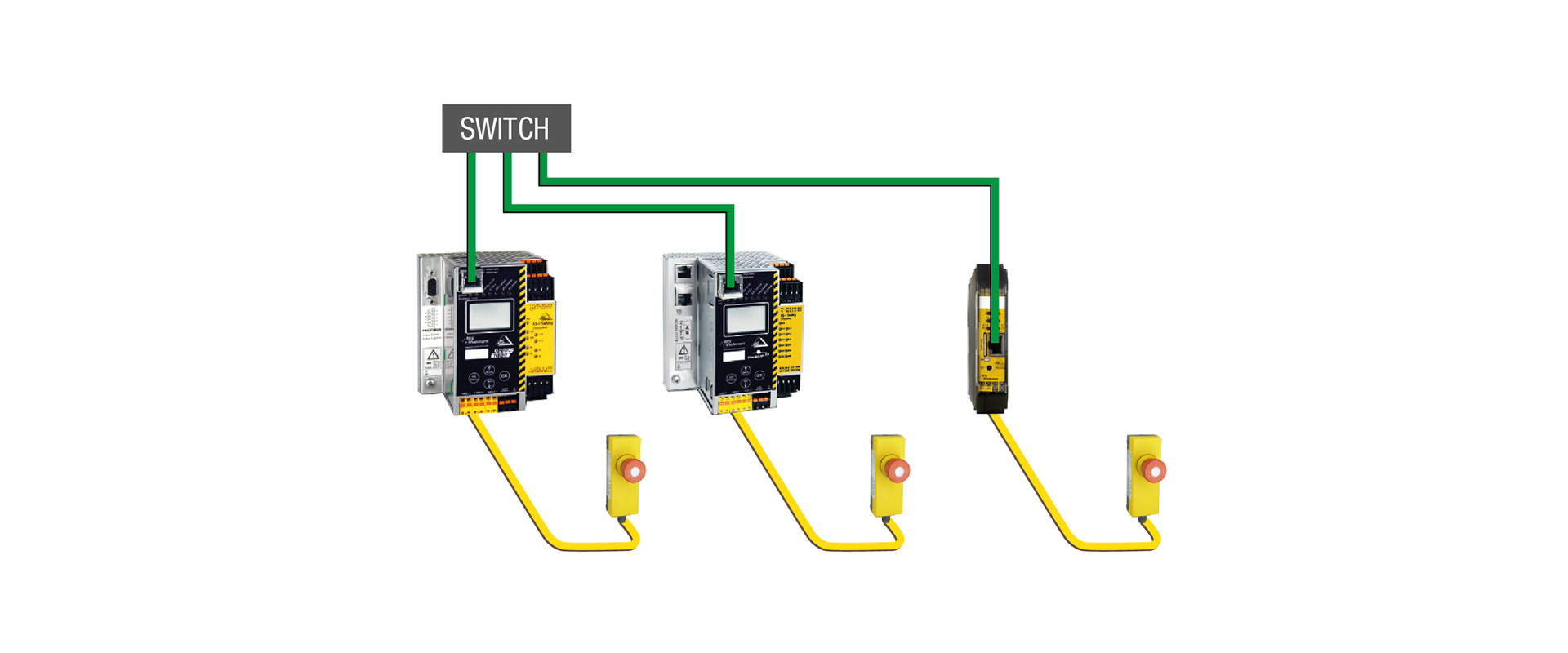
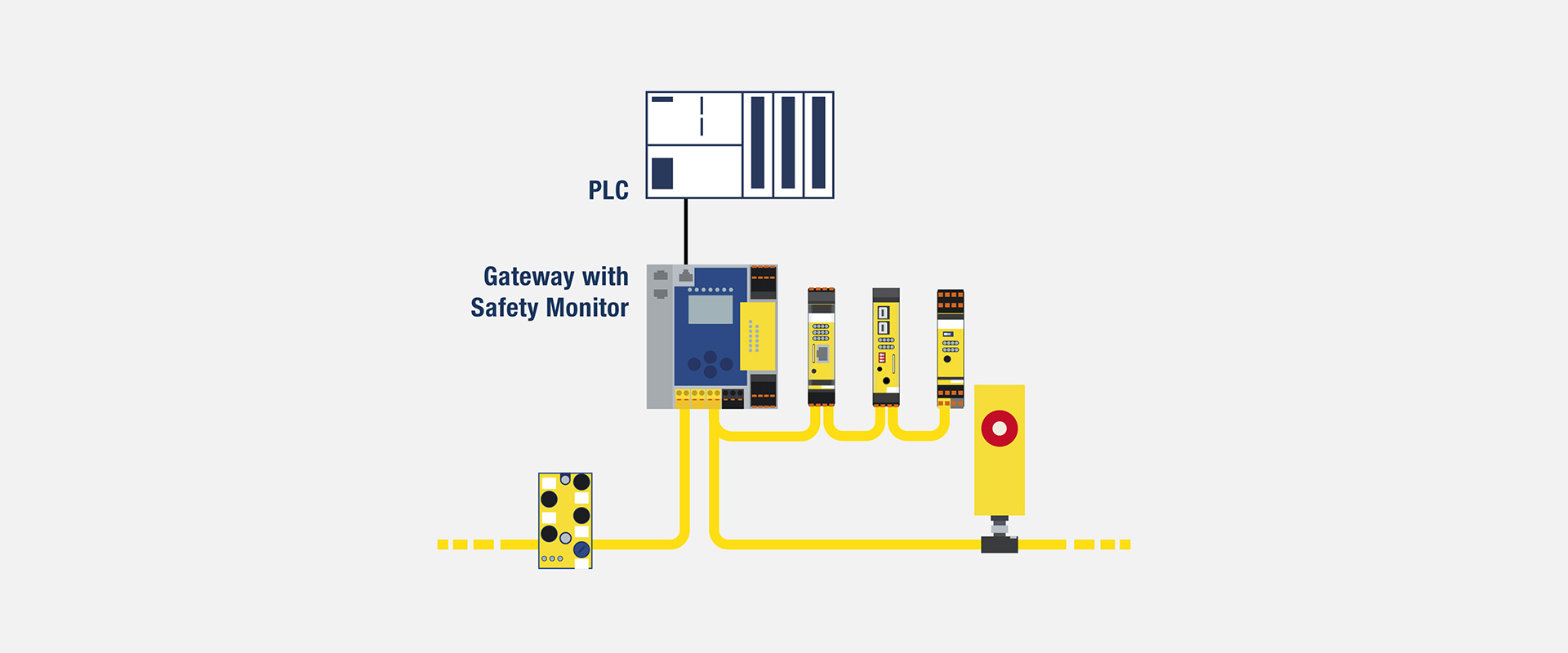
The ASi-5/ASi-3 gateway serves as a bridge between field modules and higher-level PLCs or industrial Ethernet systems. Bihl+Wiedemann’s portfolio includes gateway options for PROFINET, EtherNet/IP, EtherCAT, and other higher-level networks; however, not all products support all these protocols. The system must be configured using the correct gateway model that corresponds to the specific project requirements and facility standards. Additional features, such as the presence of two ASi circuits or integrated safety monitoring systems, also vary depending on the model selected.
The PLC data model must map motors not only by their serial number but also by their physical location, equipment label, and maintenance status. Command words, speed set values, status bits, and diagnostic bytes are stored in a version-controlled interface document. Even if ASi-3 and ASi-5 devices are connected to the same field cable, the data lengths and update behaviors may differ in the PLC. An HMI alarm should not merely indicate an “ASi fault”; it should also provide information regarding the circuit, address, channel, and possible cause of the issue.
Turn diagnostic data into maintenance decisions
ASi-5 offers more than increased data capacity. Bihl+Wiedemann describes channel diagnostics such as output short circuits and sensor-supply overloads, plus drive-specific motor current and temperature where supported. Availability depends on the product and interface. Do not assume that every inverter parameter automatically appears in the ASi process image.
On the maintenance screen, in addition to the immediate alarm, if the timestamp, the number of occurrences, and the last valid value are also stored, it becomes easier to identify recurring issues. Possible causes include increased current, mechanical jams, bearing problems, excessive load, or incorrect slope settings; however, no automatic conclusion can be drawn based on a single piece of data. A sensor power supply error must be confirmed by checking the cable or connector. Only when the diagnosis is properly correlated with the appropriate maintenance steps can meaningful information be obtained.
Distinguish safety and standard control correctly within the project
In the ASi infrastructure, standard and safety signals can be transmitted over the same profile cable. However, the stop command of a standard motor module alone does not constitute a safety function. Functions such as emergency stop, door monitoring, safe torque interruption, or safe speed control are designed based on a risk assessment; the required performance level is achieved through appropriate safety devices and suitable safety monitoring systems. The presence of passive safety connections in some drive modules does not mean that the module can perform safety-related functions on its own.
When the conveyor is restarted, the position of the products in the various zones, the amount of energy stored, and the status of the operating subsystems are checked. If the maintenance area has been isolated, it is determined in advance whether the other areas can operate safely. After an emergency, instead of the control program continuing automatically from where it stopped, the presence of products and the status of adjacent zones are re-verified. The confirmation of safety conditions is recorded separately from the routine production validation process.
24 V and 48 V auxiliary power distribution
In motorized roller conveyors, both 24 V and 48 V drives can be used within the same facility. Bihl+Wiedemann’s 48 V solution highlights the dual power transmission potential of 48 V motors—offering twice the power at the same current compared to 24 V options—and the advantages it offers in energy distribution. The official system includes gray-profile cables for 48 V AUX, local 48/24 V converters, and compatible motor modules. The gray cable serves as a visual indicator to prevent confusion with the black 24 V AUX cables; however, it does not replace proper voltage control measures.
The power supply requirements, cable cross-section, voltage drop, simultaneous start-up, regenerative energy, and protection coordination are determined through electrical calculations. Devices powered by 24 VDC ASi should not be connected to a 48 VDC system. When a converter is used, the local sensor load, output current, and short-circuit behavior must also be taken into account. The segmentation of motor power supplies may differ from that of the network; therefore, these two systems should be represented separately in the drawings.
ASIMON360 and commissioning
Bihl+Wiedemann offers the ASIMON360 software together with the hardware catalog of the ASi network, device configuration options, online data display functions, and ZPA commissioning procedures. The ability to copy the same set of initial parameters across multiple drives of the same type can significantly reduce the need for manual reconfiguration. In compatible solutions, automatic parameter restoration after device replacement can further facilitate the commissioning process. The specific scope of these functions should be confirmed based on the selected devices and drives.
During commissioning, the network and addressing settings are checked first, followed by the individual motor directions, sensors, and zone logic. Instead of enabling the entire line in automatic mode all at once, the power distribution sections and the conveying zones are verified step by step. Before copying parameters, any differences in motor power, reduction ratio, roller diameter, or mechanical orientation are filtered out. The software project, gateway configuration, PLC code, and drive parameters are all backed up with the same revision label.
Acceptance testing must include more than an empty conveyor
- Starting, stopping, changing direction, and adjusting speed for the lightest, nominal, and heaviest products.
- During high-rate product input, zone occupancy, ZPA behavior, and the time required to empty the buffer zone.
- Proper matching of ASi-3 binary commands with ASi-5 cyclic values in PLC applications
- Diagnosis and HMI alarm that occur when the connection to a motor, sensor, or module is disconnected.
- Voltage drop within the upper and lower tolerance ranges of the supply voltage, along with simultaneous starting.
- Gateway: Addressing and parameter reloading during the replacement of the drive or motor module.
- Emergency stop, protective doors, communication loss, and restart scenarios.
- During the shift, the motor current, temperature, error rate, and actual product flow rate were monitored.
Information required for quotations and selection
- Conveyor layout, number of zones, zone lengths, and physical driving points.
- Motorized coils: Manufacturers of DC motors or AC motors/frequency converters, as well as complete systems.
- 24 V or 48 V auxiliary power supply, motor currents, starting profiles, and cable lengths.
- Commands, feedback, speed, ramps, parameters and diagnostics for every motor
- The number, connection method, and power supply requirements of local photoelectric sensors and other types of sensors
- ASi-3 and ASi-5 node distributions, process data lengths, and target cycle times
- Field network, PLC platform, gateway redundancy, and plant addressing standard.
- IP protection class, cable channel depth, ambient temperature, and cleaning method
- Safety functions, safe stop methods, local isolation, and reset mechanisms.
- ZPA, product recipe, allowable flow rate, range of spare parts and maintenance screens
The right conveyor architecture does not necessarily apply the same level of technology at every point. The ASi-3 model can efficiently handle simple, dual-control tasks; the ASi-5 model, on the other hand, is designed to handle cyclic speed and ramping functions, serial drive interfaces, and more complex control requirements. Bihl+Wiedemann’s motor-specific modules, profiled cable systems, and integrated gateway solutions enable the combination of these two functional layers in a single application. Oskon allows for final selection based on factors such as motor type, drive interface, actual zone logic, power consumption calculations, and safety requirements.
Official Bihl+Wiedemann resources
- Bihl+Wiedemann – Conveyor and drive solutions for ASi-3 and ASi-5 applications.
- Bihl+Wiedemann — Drive solutions product selector
- Bihl+Wiedemann – Explanation of compatibility with ASi-3, ASi-5, and IO-Link
- Bihl+Wiedemann — BWU4893 ASi-5 cable channel motor module
- Bihl+Wiedemann — Official website for BWU4893/BWU4894
- Bihl+Wiedemann — BWU3605 ASi-3 binary drive-control module
- Bihl+Wiedemann — BWU4718 ASi-5 Modbus TCP drive module
- Bihl+Wiedemann – ASi-5-based 48 V drive systems and power distribution solutions
- Bihl+Wiedemann – Material handling and drive control (Turkish-language pages and videos)
- Bihl+Wiedemann – drive solutions for ASi-5 and ASi-3 systems (video)