Process instrumentation is the measurement layer that converts field information on pressure, level, flow, temperature, weight and valve position into control decisions. Siemens SITRANS offers sensors, transmitters, controllers, communication options and digital tools for these tasks. Selecting the right device requires more than identifying the measured variable: fluid properties, measurement range, process connection, environmental conditions, hazardous-area classification, material compatibility, accuracy, maintenance access and control-system integration must be assessed together. Using SITRANS P320/P420 pressure transmitters, the SITRANS LR100 level radar series and SITRANS FM MAG 8000 flowmeters as examples, this guide explains how to move from a product family to the exact variant required.
A good measurement point starts with a data sheet
First, define the purpose of the instrument tag. A pressure gauge may be sufficient for operator monitoring, whereas a control loop may require faster response and greater stability, and a safety function may require independence, systematic capability and proof testing. Document the normal operating range, start-up and cleaning conditions, minimum and maximum possible values, allowable total error and required response time. The description ‘0–10 bar transmitter’ is not a complete purchasing specification: it omits overpressure limits, process temperature, diaphragm material and connection standard.
Fluid properties are as important as the measurement range. Corrosion, abrasion, viscosity, solids, gas bubbles, density changes, crystallization and hygiene requirements influence the measurement technology. Tank geometry, agitators, internals, foam and condensation affect level measurement; straight pipe runs and valve and pump locations affect flow measurement; impulse-line length and ambient temperature affect pressure measurement. Select the device for the required performance under actual installation conditions, as well as its laboratory accuracy.
| Measurement task | Questions for preliminary selection | Particular points to verify on site |
|---|---|---|
| Pressure / differential pressure | Type of pressure, span, static pressure, overload, process temperature, and the material being wetted. | Process connection, manifold, impulse line, zero position, sealing and damping |
| Radar level measurement | Measurement range, product dielectric properties, tank structure, foam, steam, dust, and Ex zones. | Nozzle, beam clearance, obstructions, false-echo suppression, empty/full references and overflow protection |
| Electromagnetic flow rate | Conductivity of the medium, pipe diameter, speed range, compatibility of the coating/electrode, and accuracy class. | Full pipe, earthing, flow direction, cable, installation location, and verification. |
| Temperature | RTD/thermocouple types, measurement range, accuracy, response time, requirements for sheath and thermowell | Dip length, heat conduction, vibration, sensor redundancy, and cable compensation |
| Weighing / dosing | Capacity, resolution, mechanical load path, impact, and environmental factors. | Mounting forces, bridging, calibration weights, cables, and zero stability. |
Pressure measurement: SITRANS P320 and P420
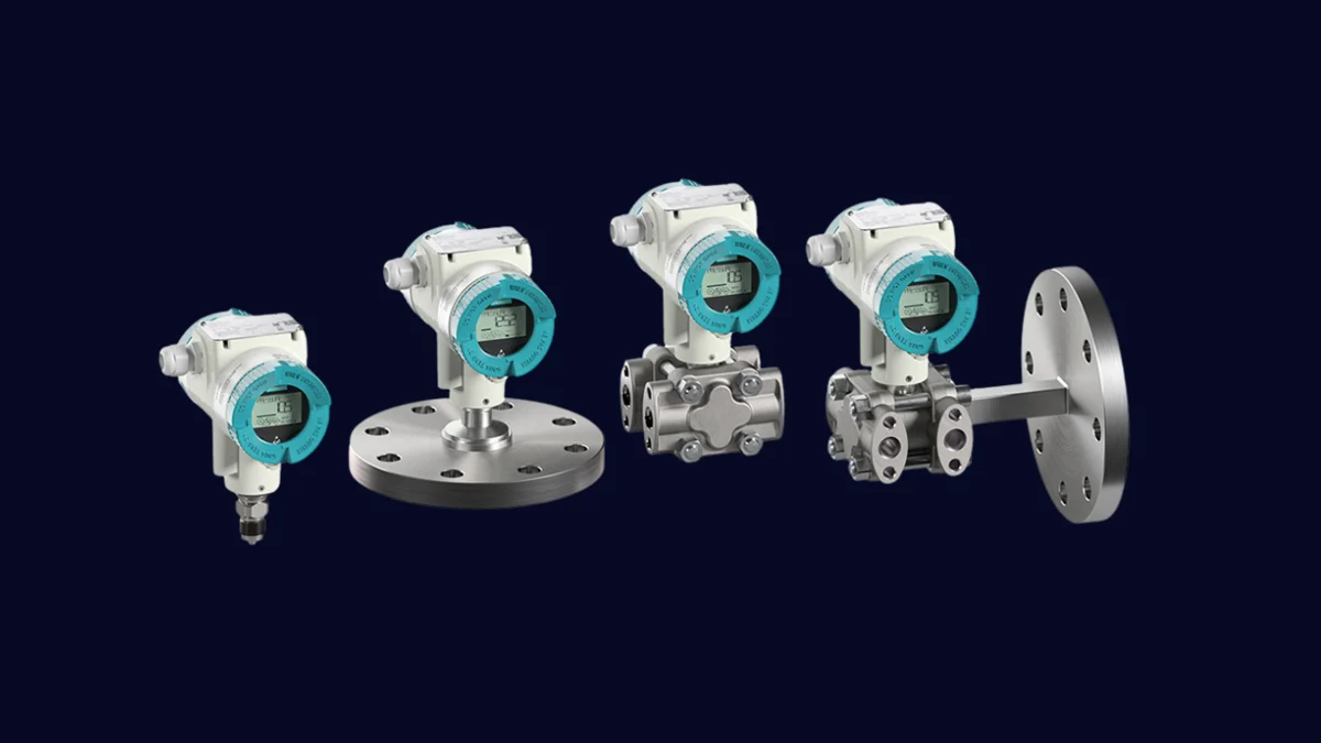
The SITRANS P320/P420 family offers configurations for gauge, absolute and differential pressure, as well as level, volumetric flow and mass flow applications based on differential pressure. Siemens’ current product page distinguishes the P320 and P420 by accuracy and digital functionality. The P420 adds measured-value storage and trending within the device alongside its higher specified accuracy. The range of measuring cells and variants allows the family to serve different instrument-tag requirements.
In the selection process, the measurement range and the upper limit must be determined first. Although it is theoretically possible to use a cell with a wide range for a narrow measurement span, factors such as the turndown ratio, total error, and stability objectives must be taken into consideration. For differential pressure applications, factors such as static pressure, bilateral overload, and manifold configuration must be considered; for remote diaphragm seals, parameters such as the filling fluid, capillary length, ambient temperature, and installation height are important. The materials of the components that come into contact with the medium must be chemically compatible with the product; moreover, the process connections, as well as the type of seals and bolts used, must meet the mechanical standards of the facility.
The communication option is not merely a matter of choosing “digital” or not. The latest Siemens website lists 4–20 mA/HART, PROFIBUS PA, FOUNDATION Fieldbus, and PROFINET over Ethernet-APL as available options within the same family; however, not all of these interfaces are available in every single configuration of the same order. It is necessary to determine the support for control systems, the required cable infrastructure, the appropriate Ex certification for explosion-proof applications, the device management capabilities, and the standards for spare parts. Diagnostics based on NAMUR NE 107 can provide the maintenance team with information on the status of the systems; in addition, it is essential to ensure that alarms are properly prioritized and correspond to appropriate actions within the DCS system.
Interpreting limits in functional safety versions correctly
Siemens describes options in the P320/P420 family that support SIL 2/3 applications under IEC 61508, together with Remote Safety Handling. This does not mean that the transmitter alone makes an entire safety instrumented function SIL 3. The exact device variant’s certificate, hardware fault tolerance, restrictions of use, safe failure rates, proof testing, architecture, and contributions of the logic solver and final element must be assessed together. ‘SIL capable’ must be distinguished from the verified SIL of a specific safety instrumented function (SIF).
Remote safety procedures can reduce the need for on-site visits and exposure to hazardous areas; however, they do not eliminate the requirements for preventing unauthorized modifications, independent verification, and record-keeping. It is essential to document who made the changes, on which device, and using which version of the software. The commissioning and proof-test procedures must be carried out in accordance with the methods and diagnostic procedures permitted by the relevant safety guidelines.
Non-contact level measurement: the SITRANS LR100 series
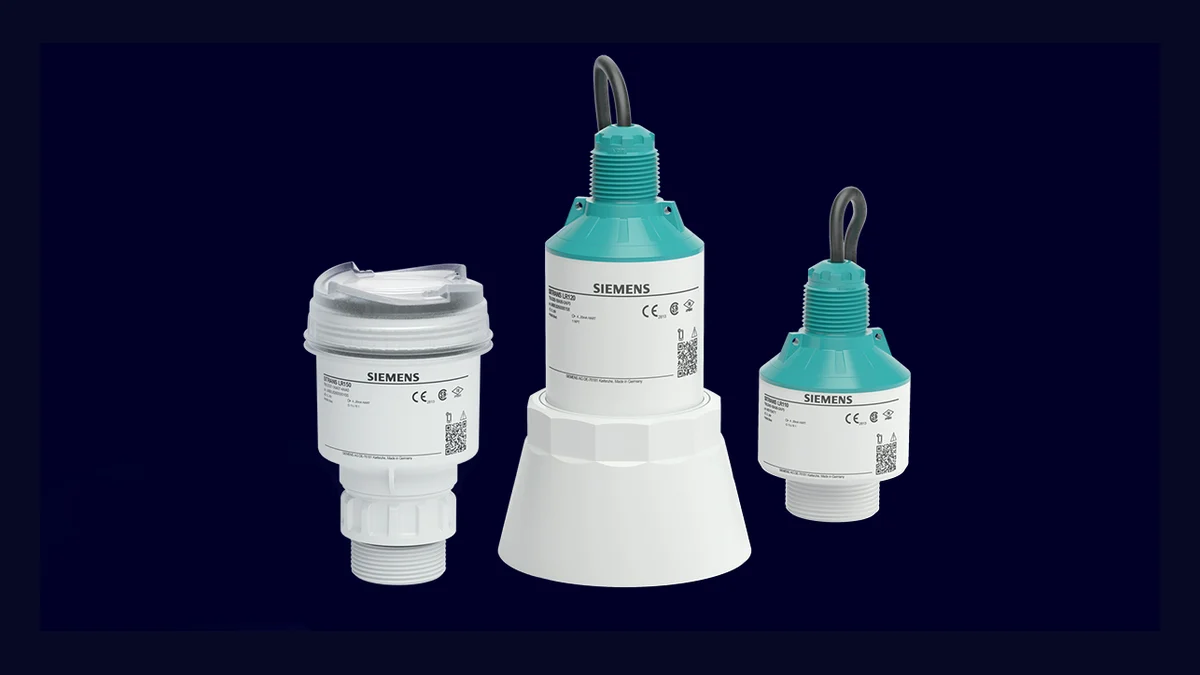
The SITRANS LR100 series comprises compact 80 GHz radar transmitters for liquid or solid level measurement. Siemens’ current product page distinguishes the LR100, LR110, LR120, LR140 and LR150 according to measurement distance, communication, local display, hazardous-area approval and submersion protection. A narrow radar beam can simplify installation through small existing openings and help avoid tank internals. Bluetooth commissioning through SITRANS mobile IQ can simplify setup in locations that are difficult to access.
Selecting radar technology does not eliminate installation engineering. An antenna face recessed inside a nozzle, alignment toward an agitator or filling stream, measurement through metal-reinforced plastic, or false-echo mapping performed against a full tank can produce unstable results. Record tank dimensions, measurement reference, blocking distance, overflow conditions, product dielectric properties and surface movement in the application specification. Assess the available echo margin under the most demanding process conditions instead of relying solely on the nominal maximum measurement distance.
A continuous level transmitter and an independent high-level alarm serve different purposes. Siemens’ description of safe measurement on the LR100 page also recommends considering the alarm or standby level switch as part of an appropriate solution. In cases where a overflow poses a risk of injury to people, environmental damage, or significant asset loss, the independence of the protective mechanisms and relevant standards must also be taken into account. The convenience of Bluetooth technology does not eliminate the need for proper access controls in the field; the pairing process, user permissions, and maintenance requirements are all subject to the facility’s cybersecurity procedures.
Flow measurement in water networks: SITRANS FM MAG 8000
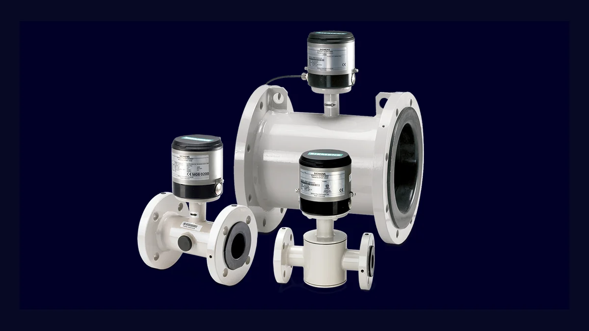
The SITRANS FM MAG 8000 is a family of electromagnetic flowmeters that can operate using batteries, particularly in applications involving water intake, distribution, billing, and irrigation. The current product page distinguishes between basic and advanced models based on consumption patterns, system performance requirements, and remote communication needs. The measurement tube, which contains no moving parts, features a design that minimizes mechanical wear and pressure loss. Its IP68-rated enclosures and various power options enable it to be used in locations where there is no access to grid electricity or where there is a risk of water intrusion.
For electromagnetic measurement, the fluid must possess sufficient electrical conductivity, and the pipe must be filled completely within the measurement section. Non-conductive fluids such as gases, vapors, or hydrocarbons do not meet this requirement. The selection of the pipe should not be based solely on its diameter; flow velocity, pressure loss, accuracy, and future capacity must also be considered at minimum, normal, and maximum flow rates. The electrode and coating materials must be compatible with the chemical properties of the fluid, while the flanges and the pipe’s pressure-class designation must conform to relevant industry standards.
Siemens lists a 0D upstream/downstream straight-run requirement as a MAG 8000 benefit. Nevertheless, installation effects from pump outlets, control valves, partially filled pipes, air pockets and strong vibration must be assessed using the application manual. Follow the manufacturer’s instructions for grounding and equipotential bonding. For underground installations, protect cable glands, junction boxes, antennas and access covers against water ingress as well as the meter body.
Other measurement tasks: temperature, weighing and valve position
A single plant standard does not consist of just three product families. Siemens’ current SITRANS product portfolio includes temperature transmitters, weighing and dosing solutions, digital valve positioners, as well as various flow measurement principles and supporting digital components. For temperature transmitters, factors such as the type of sensor, the mechanical design of the thermowell, the immersion length, and the response time are just as important as the accuracy of the device itself. Features like dual sensors or hot backup options are only available when the appropriate product variant is selected and correctly installed.
For a valve positioner, specify the linear or rotary actuator, air pressure, stroke, fail position, feedback and hazardous-area approval. For weighing systems, resolve load-cell capacity, mechanical load path, vibration and calibration method before selecting the electronic module. For non-conductive liquids, gases, steam or direct mass-flow measurement, consider Coriolis, ultrasonic, vortex or another suitable principle instead of an electromagnetic meter. Technology selection follows from both the process characteristics and the measurement objective.
Control system integration and device data
A 4–20 mA signal is a straightforward, widely used interface. Digital communication such as HART can provide device status and parameter access alongside the measured value. Field networks such as PROFIBUS PA and PROFINET over Ethernet-APL have different topology, power, explosion-protection and engineering requirements. A protocol being available in a product family does not mean that its device drive and all functions are supported by the existing DCS version. Verify device-description files, integration packages, control-system versions and supported parameters in a pilot connection.
Diagnostic data must be connected to the maintenance workflow to deliver value. Assign states such as ‘maintenance required’, ‘out of specification’ and ‘function check’ to a responsible team, priority and recommended action, rather than displaying colors alone. Compare measurement quality with the physical process: device self-diagnostics cannot always identify incorrect installation, a blocked impulse line or incorrect sizing. Trends, laboratory results, mass balances and reference measurements can support root-cause analysis together.
Installation, commissioning and maintenance checks
- Document review: Compare the tag data page, order code, certificate, material information, and process details with those of the received device.
- Mechanical assembly: Check orientation, support, torque, seals, antenna clearance, fully filled pipe, manifold and access against the product instructions.
- Electricity and networking: Verify the power supply, shielding, grounding, polarity, Ex protection barrier, cables, and device addresses using the loop diagram.
- Parameter setting: Load the range, unit, damping, failure current, tag, totalizer and diagnostic settings from the approved parameter list.
- Function testing: Record zero/span values or reference points, as well as direction, DCS scaling settings, alarm conditions, and any behavior related to communication interruptions.
- Initial comparison: Save the initial operating trend under normal process conditions as a healthy-state maintenance reference.
- Change management: Reassess measurement effects after changes to firmware, sensors, parameters, piping/tanks or process recipes.
Information required in a quotation request
- Tag number, measurement purpose, normal/minimum/maximum value, and allowable total error.
- Fluid composition, density, electrical conductivity, viscosity, solid/gas content, and material compatibility.
- Process and ambient temperature, pressure, overload, vibration, external environment, and protection class.
- Process connection, pipe/tank dimensions, nozzle, liner, electrode, diaphragm and seal materials
- ATEX/IECEx certification or other regional approvals, as well as requirements related to the device category and installation location.
- 4–20 mA/HART, fieldbus, Ethernet-APL, Bluetooth, or wireless communication options, along with DCS compatibility.
- Local indicators, buttons, remote access, data recording, diagnostic functions, and cybersecurity requirements.
- Calibration certificate, verification tool, proof test, spare parts, and commissioning services.
The right process instrument is not necessarily the one with the highest accuracy value listed in the catalog; rather, it is the device that reliably generates the information required under actual process, installation, and operational conditions. The SITRANS family offers a wide range of options. To turn this diversity into a competitive advantage, every decision—from the family name to the order code—is made transparent through tag data sheets, up-to-date manufacturer documentation, and functional tests in the field.