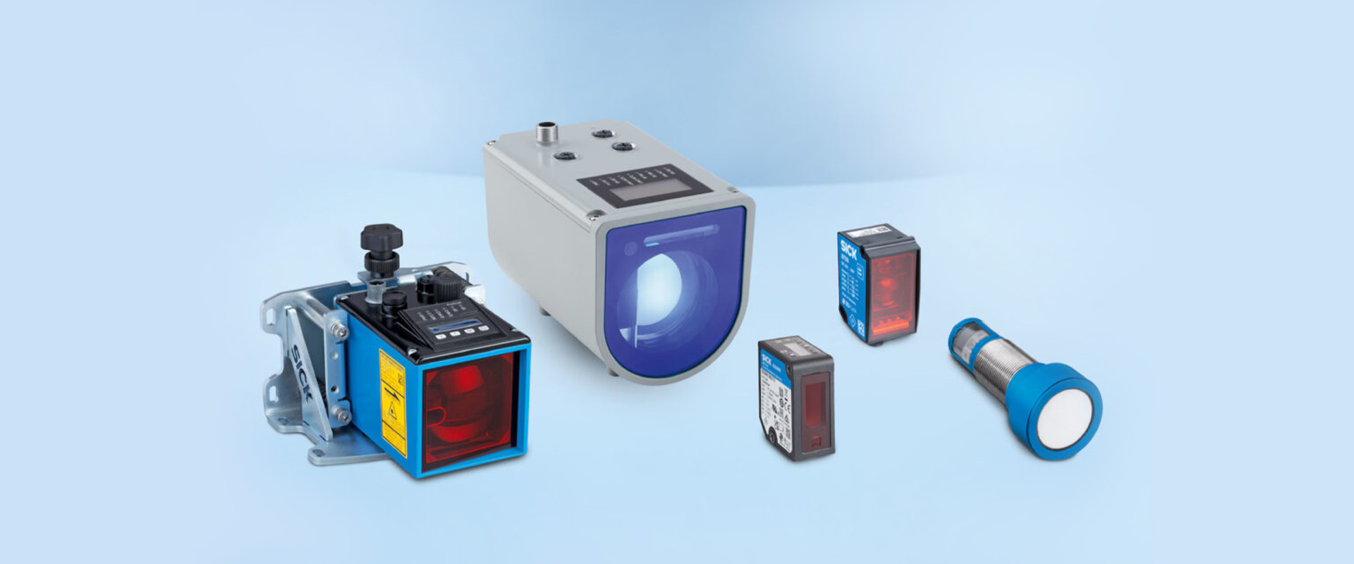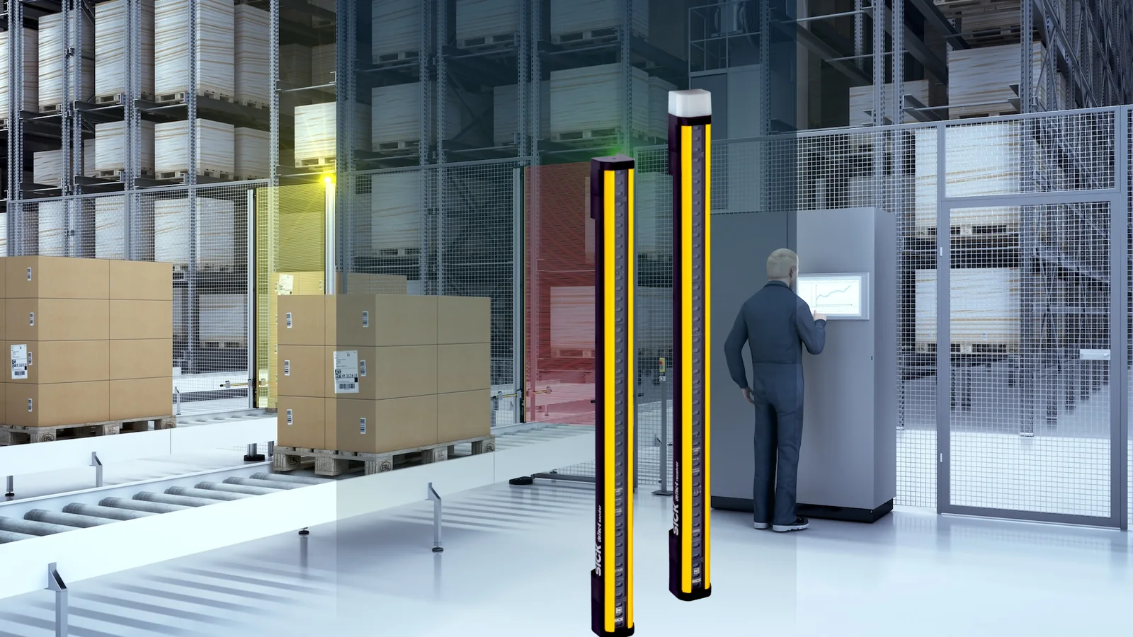
Encoders and photoelectric sensors often perform similar functions within an automation system, but they do not generate the same type of information. An encoder converts the position, speed, and direction of rotational motion into electrical signals, which are then transmitted to a drive shaft or linear mechanism. On the other hand, a photoelectric sensor detects the presence of an object, its movement, its edge, or a specific distance range by emitting and detecting light. Therefore, the right solution lies not simply in selecting the appropriate detection range or pulse rate from a catalog, but in clearly defining which physical phenomenon the control system needs to monitor and with what level of accuracy and response time.
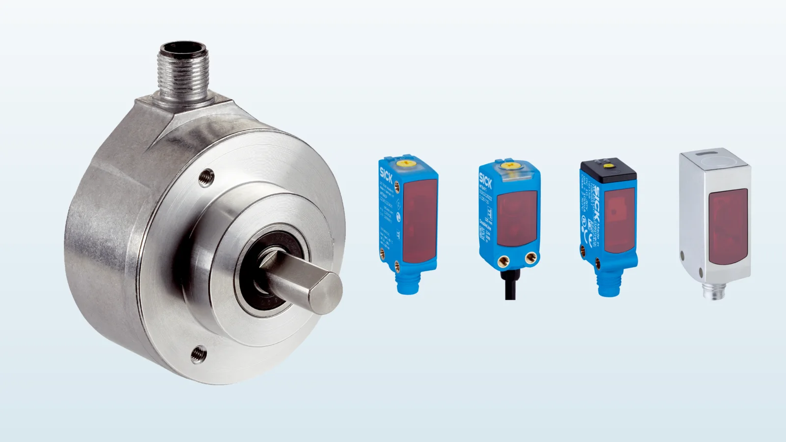
This catalog and selection guide takes the SICK DFS60 incremental encoder family and the W4 miniature photoelectric sensor family as two specific examples. It should be noted that the feature combinations specified at the family level are not necessarily identical in each individual product order. Parameters such as shaft type, electrical interface, connection method, material of the housing, optical principle, light source, switching output, and environmental resistance vary depending on the selected model. The final product code should be verified against the corresponding technical data, installation instructions, interface specifications of compatible devices, and actual application examples.
First define the event to measure and the control decision
In a conveyor system, although functions such as speed regulation, cutting length control, product counting, and jam detection may seem similar, they actually require different types of sensor data. The pulse sequence generated by the encoder enables the controller to determine the distance and speed of the moving object. Meanwhile, the switching signal from the photoelectric sensor confirms that the product has reached a specific point. However, using only an encoder may prevent the detection of issues such as belt slip or products getting stuck on the conveyor; whereas relying solely on a photoelectric sensor makes it impossible to obtain detailed information about the object’s movement between the two detection points. In critical applications, combining these two signals allows for a comparison between the expected movement trajectory and the actual position of the product as it moves along the conveyor.
Merely stating “encoder” or “photoelectric sensor” in the specification is insufficient. It is necessary to specify the axis to be measured, the maximum and minimum speeds, the acceleration, the direction of rotation, the desired resolution, the object size, the surface color, the brightness, the transparency, the background distance, the cycle time, and the allowable error rate in detection. The voltage level of the control input, the counting frequency, the input filter, and the IO-Link master infrastructure must also be known before selecting the sensor. This will prevent the use of a solution that is physically connected but electrically or temporally incompatible.
DFS60 incremental encoders: the interface matters as much as resolution
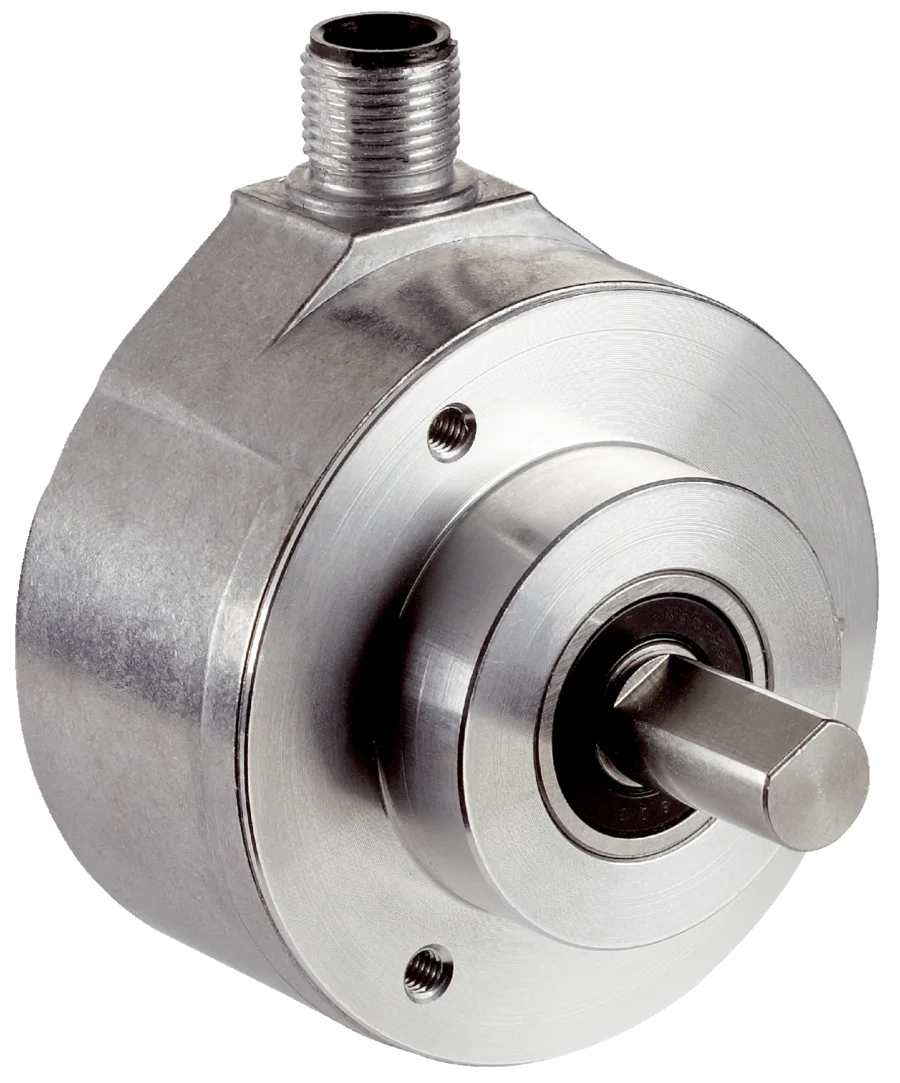
SICK positions the DFS60 within its family of programmable, high-resolution incremental encoders with a body diameter of 60 mm. The official product page lists various features, including a maximum of 65,536 pulses per revolution, options for solid, blind hollow, and through-hollow shafts, and communication interfaces such as TTL, RS-422, HTL Push-Pull, and Sin/Cos. The family also offers M12 and M23 male connectors or universal cable connections. IP65 and IP67 protection classes are also specified. These features constitute the range of options available within this product family; it does not mean that all features are necessarily included in every single variant.
The number of pulses determines how many sections the mechanical rotation is divided into, but it does not in itself constitute an absolute measure of accuracy. Factors such as shaft misalignment, coupling flexibility, bearing clearance, vibration, the controller’s counting capacity, and the mechanical transmission ratio all contribute to the overall measurement uncertainty. A very high number of pulses may exceed the frequency allowed by the input hardware. The maximum pulse frequency should be determined by multiplying the number of pulses per revolution by the maximum rotational speed, and this value must be taken into account when selecting the controller’s fast-counting input options. The A/B phase signals provide direction information, while the presence of a zero-pulse signal indicates a reference event; the signal format is confirmed according to the selected electrical variant.
Treat the mechanical connection as part of the measurement chain
Encoders with solid shafts must be connected to the motor or machine shaft using suitable couplings. A rigid connection that does not compensate for any misalignment can impose unwanted radial or axial loads on the encoder bearings. For models with hollow shafts, the shaft diameter, clamping elements, and torque support must be selected together. The inclination of the mounting surface, shaft vibrations, and the misalignment allowed by the coupling must all fall within the manufacturer’s specified limits. The cable should not be stretched in a way that could cause the encoder housing to rotate; adequate fixation and bending margins must be ensured in areas subject to vibration.
The level of protection provided by the body only becomes effective when the device is correctly installed and the connections are properly matched. An exposed connector, a damaged seal, or incorrect tightening of the cable gland/fitting will not provide the same level of protection. In areas where washing, exposure to strong chemicals, or corrosion are likely, the stainless steel DFS60 Inox variants may also be considered; however, the material compatibility must be verified in relation to the chemicals used, the operating temperatures, and the cleaning methods applied. The mechanical and environmental specifications of the standard DFS60 model should not be assumed to be the same as those of the Inox variant.
Programmability can reduce spare variants, but requires configuration discipline
In the DFS60 series, parameters such as resolution, counting direction, and zero pulse can be programmed in specific variants, enabling a common hardware approach for various applications. SICK’s product page lists the PGT-10-Pro handheld device and the PGT-08-S PC-based controller as programmable options. However, this programmability also underscores the importance of product labeling and backup procedures. Two encoders with the same hardware can exhibit completely different control behaviors when programmed with different parameters.
The parameter file, product code, firmware, tool version, and modification date, once incorporated into the system, must be included in the maintenance documentation. After any modifications, not only the mechanical installation but also the output level, pulse count, direction, reference signal, and the scaling factor in the controller must be verified through functional testing. For models equipped with a remote reset function, electrical and software measures must be in place to prevent accidental activation of the relevant inputs.
W4 miniature photoelectric sensors: different optical tasks in a small housing
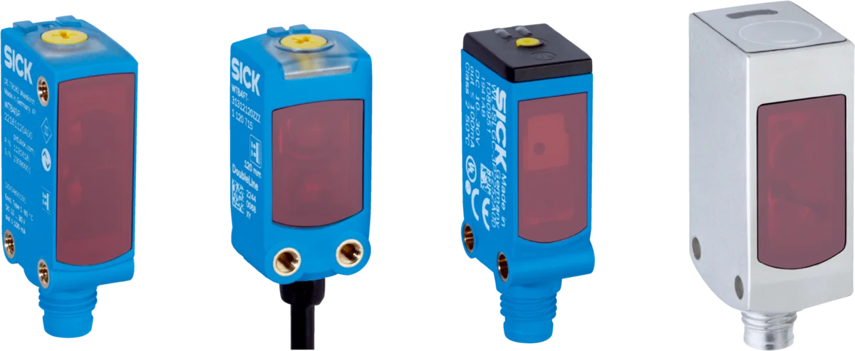
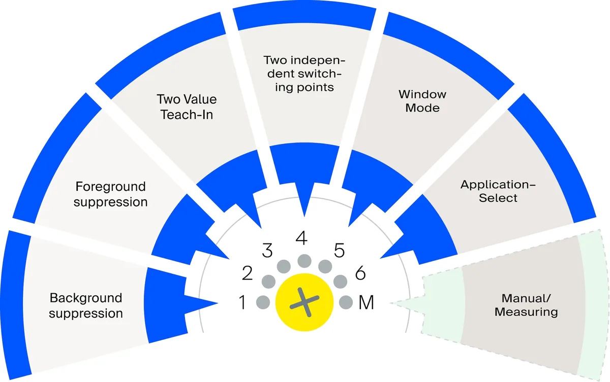
The SICK W4 family offers a wide range of body types, materials, and light sources to enable the detection of various object characteristics in confined installation spaces. The official product page lists optical technologies such as DoubleLine, ClearSens, V-optic, and Spot Size Recognition; features including two independent switching points, a fast distance value output, and DustAlert; as well as options like PinPoint-Pro, PinPoint, infrared LEDs, and red lasers. Depending on the model, the devices also support IO-Link communication, optical alignment functions, and various on-device diagnostic tools.
Photoelectric sensors use several detection principles. In a through-beam sensor, the transmitter and receiver have separate housings and detect an object interrupting the beam. A retro-reflective sensor places both in one housing with a reflector opposite. A diffuse-reflective sensor evaluates light returned from the object; background suppression distinguishes target and background by distance. Select the principle according to the object surface, mounting access, cabling, sensing distance, and unwanted reflections.
Assess objects and backgrounds using actual samples
Dark, shiny, porous, irregular, or transparent materials present different optical challenges. Dark surfaces reflect little light, while shiny surfaces may cause reflections that mislead the sensor. Porous objects may allow a small light spot to pass through intermittently, resulting in oscillating signals at the output. Transparent films, bottles, or trays may not produce sufficient contrast when measured using the reflection method. The appropriate technologies and light sources available in the W4 system must be tested at various distances and angles, both in relation to the target sample and the background.
The light spot size is determined in conjunction with the minimum detail that can be detected and the operating range. A very small spot size allows for the detection of fine edges, but may result in more variable measurements on textured or porous surfaces. Linear optical systems, on the other hand, provide more stable sampling results on irregular surfaces. Do not design the operating range at the catalog maximum; adequate alignment tolerances, allowance for contamination, and minimal reflectivity of the target object are essential for reliable performance. Nearby bright machine parts and the light from opposing sensors must also be taken into account during the testing process.
IO-Link offers more than a communication cable
In suitable W4 variants, IO-Link enables the control system to manage sensor parameters and retrieve information such as distance, reset settings, operating hours, or diagnostic data. This feature is particularly valuable for parameter configuration based on specific requirements during product replacement, monitoring of detection accuracy, and transmitting contamination alerts to the maintenance system. However, the presence of IO-Link does not imply that all W4 products offer the same process data or functions. It is essential to verify the device definition file, process data length, cycle time, port class, and master compatibility specific to each order code.
The PNP or NPN configuration of the switching output, its on-off behavior, connection diagram, and load current must be matched accordingly to the PLC input. Any settings made via teaching functions or on the device itself must be recorded in the commissioning parameters. Even when using IO-Link, it is essential to define the safe default state, the behavior in the event of a connection loss, and the value validation checks within the PLC program. A standard photoelectric sensor must not be used in place of a safety-certified protective device.
| Decision area | Points to verify for DFS60 encoders | Points to verify for W4 photoelectric sensors |
|---|---|---|
| Main task | Speed, direction, incremental position, reference. | Object, transition, edge, distance window |
| Mechanical/optical design | Solid or hollow shaft, flange, coupling, torque support | Through-beam, retro-reflective, or diffuse-reflective principle; mounting angle |
| Resolution | Pulses per revolution, mechanical transmission, and counter frequency | Light spot, minimum object size, distance, and response time. |
| Electrical interface | TTL, RS-422, HTL; push-pull or sine/cosine signal types; controller compatibility. | PNP/NPN, open/closed states, IO-Link, and process data |
| Environmental conditions | IP rating, temperature, vibration, shaft load, and body material | Dirt, ambient light, temperature, washdown, chemicals, and mutual interference |
| acceptance test | Direction, pulse scaling, maximum speed, reference signal, and power interruption | All samples, including background, speed, contamination level, and false triggering events. |
Combined use: compare expected movement with the actual product
In cutting, labeling, or packaging machines, the encoder determines the theoretical position of the product based on the movement of the conveyor belt; the photoelectric sensor detects the actual front edge of the product to ensure accurate timing. The PLC can detect issues such as misalignment, interrupted transmission, or product jams by monitoring the difference between these two signals. When using this approach, the switching delay of the photoelectric sensor and the resolution of the encoder must be explicitly taken into account in the control logic. Instead of continuously adjusting the sensor position via software offsets, it is essential to maintain a mechanical mounting reference.
When the speed is variable, a control system that operates only based on a fixed time delay may result in incorrect position determinations. Encoder-based distance detection ensures a more consistent physical distance measurement despite speed changes, while photoelectric sensors confirm the actual presence of the object. To obtain reliable results, each signal’s timestamp, as well as the input filter settings and the PLC’s processing cycle, must be carefully evaluated. For very fast-moving objects, the sensor’s response time and the minimum output signal width must fall within the limits that the controller can handle.
Commissioning and maintenance acceptance plan
During the commissioning of the encoder, mechanical deviations, the tightness of connections, and the condition of the cable shield are checked; at low speeds, the direction and pulse count are measured, while at high speeds, the frequency and signal stability are tested. The reference procedure is also performed when the power is turned on and off. For photoelectric sensors, samples with the highest brightness, lowest brightness, maximum reflectivity, and minimum reflectivity are tested, along with empty belts, different background conditions, and expected levels of contamination. Simultaneously monitoring the sensor’s LED and the PLC input makes it easier to distinguish between optical detection results and the actual program behavior.
A maintenance plan does not solely rely on repairs after failures occur. Encoder couplings, shaft connections, cables, and connectors are regularly inspected for signs of mechanical damage. Photoelectric sensor lenses are cleaned using appropriate methods, and their reflectors, brackets, and alignment settings are checked. For devices with programmable parameters, their default settings are stored in a version-controlled manner. Even if the product code remains the same after a replacement, the configuration, wiring, and functional tests must be carried out again.
Data required for quotations and selection
- Describe its function: Indicate which of the following is required: speed, position, counting, presence detection, edge detection, or synchronization control.
- Provide the motion profile: Share information on diameter, rotational speed, acceleration, direction, mechanical transmission, and the allowable deviation.
- Describe the set of objects: Provide samples in various sizes, colors, brightness levels, degrees of transparency, as well as with different surface and background textures.
- Specify the control interface: Specify supply, TTL/HTL/Sin-Cos, input frequency, PNP/NPN, IO-Link master, and cable length.
- Record the environment: Specify the temperature, water, dust, oil, chemicals, vibration levels, ambient light conditions, and the cleaning methods to be used.
- Measure the installation area: Thoroughly assess the flange, shaft, bracket, connector outlet, cable routing, and service accessibility in three dimensions.
- Define the acceptance criteria: Describe the permitted range of counting/location errors, false detections, maximum speeds, and the system’s behavior after an error occurs.
Oskon begins the selection process for encoders and photoelectric sensors not based on the product name, but rather from the perspective of the entire measurement system. The goal is not to select the product with the highest catalog value, but rather to determine a solution that generates reliable data within mechanical, optical, and electrical limitations, can be properly integrated into the control system, and can be tested in actual application scenarios. The availability of the product and the delivery time are also confirmed at the time of the offer; however, this guide does not constitute any guarantee of automatic suitability for stock availability or specific applications.
Official technical resources
- SICK – DFS60 incremental encoder product family
- SICK – Product category: Incremental encoders
- SICK – W4 miniature photoelectric sensor product family
- SICK – Photoelectric sensors
The numerical and functional information indicates the product family to which it belongs. Exact electrical, mechanical, optical, and environmental specifications must be confirmed solely by referring to the current data sheet and instruction manual of the selected product model.