When the right surface and the appropriate dimensions are selected, vacuum gripping provides a fast, lightweight, and gentle way to handle products. However, reliability is not solely determined by the diameter of the suction cup: the suction capacity of the vacuum generator, the desired vacuum level, the porosity of the product, the surface curvature, the direction of acceleration, the hose diameter, the filter, the release mechanism, and vacuum monitoring are all crucial factors in this process. This catalog guide introduces Festo’s current range of vacuum generators and grippers, presenting them within a selection system. It also demonstrates how to verify their design specifications through comprehensive data sheets and actual component testing.
The five main elements of a vacuum system
- Vacuum production: The Venturi principle is utilized in pneumatic ejectors or, as appropriate for the application, in central vacuum systems to generate the required pressure difference.
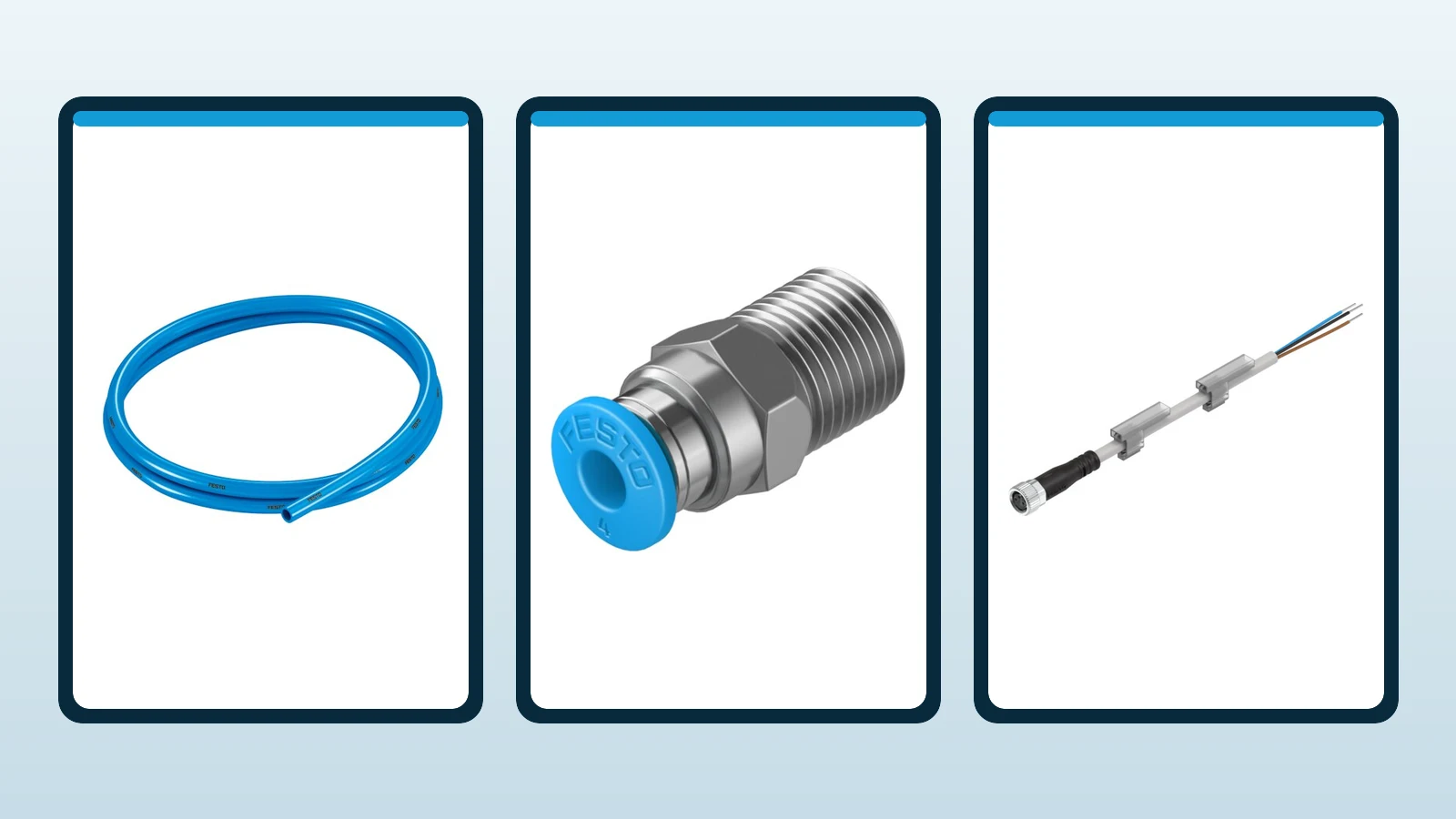
- Vacuum distribution: Tubing, distributors, fittings and filters convey vacuum to the gripper with minimal losses.
- Contact element: A suction cup or specialized near-contactless gripper provides the holding force appropriate to the product surface.
- Monitoring: The vacuum sensor confirms that the gripping condition has been established, is maintained throughout the cycle, and has been released at the end of the process.
- Control: Integrate suction, air saving, blow-off pulse, fault timing and handling-motion permission into PLC logic.
If one component is incorrectly selected, a larger suction cup or higher supply pressure may not provide a lasting solution. Long, narrow hoses increase evacuation time; porous surfaces create continuous leakage; dirty filters reduce suction flow; and bending products can break the seal. Test the design against the worst acceptable production condition, rather than a clean laboratory sample.
Distinguish vacuum level from suction flow rate
The vacuum level refers to the pressure difference created by the system relative to atmospheric pressure; the suction flow rate, on the other hand, indicates the amount of air that can be removed under specific conditions. To achieve the desired level on a sealed, small-volume component, a high flow rate may not be necessary. However, on porous cardboard, rough cast surfaces, or materials with constant leakage, the system can only maintain the target vacuum level if it is equipped with a flow rate sufficient to compensate for the leakage. Therefore, it is not appropriate to select a vacuum generator solely based on the highest achievable vacuum value.
Evacuation time depends on suction-cup internal volume, hose length and diameter, distribution volume, generator characteristics and leakage. For short cycles, locating the generator near the gripper reduces line volume. A shared central line can reduce component count and maintenance, but a leak at one point may affect other grippers. Compare centralized and distributed architectures against product variants and fault behavior.
Calculate holding force with a safety margin
The theoretical gripping force is calculated by multiplying the effective suction area by the pressure difference. In actual design, factors such as the sealing area of the suction cup lips, surface roughness, acceleration, direction of movement, center of gravity, vibration, hose pressure, and the flexibility of the product can reduce this value. During vertical lifting, the weight directly affects the gripping force; on a horizontal surface, lateral acceleration limits the sliding capacity. On oily or dusty surfaces, the coefficient of friction may also change.
The safety factor should not be assigned arbitrarily as a single value. Factors such as human access, the consequences of falling debris, dynamic movements, surface variations, and vacuum loss must all be taken into consideration. When multiple suction cups are used, it cannot be assumed that the load will always be evenly distributed; the tolerance of the frame and the curvature of the product may result in some cups bearing less of the load. Hinge joints, height-adjusting devices, or flexible connections can help improve the distribution of contact forces, but they also affect the overall movement and vibration of the system.
OVEM: vacuum generators with integrated monitoring
OVEM is Festo’s ejector family combining vacuum generation, control and monitoring in a compact unit. Listed features include a vacuum sensor, IO-Link monitoring, a central M12 electrical connection, an integrated filter, optional air saving and an adjustable blow-off pulse. Integrated solenoid valves support short switching times. These functions confirm product pickup through measured vacuum rather than a timed assumption.
The energy-saving function can reduce compressed air consumption once the target vacuum level is achieved with adequate sealing; production can be resumed when the vacuum drops below the specified threshold. However, on surfaces with continuous leakage, frequent restarts may occur, potentially reducing the expected benefits. Thresholds, hysteresis, discharge times, and error delays must be calibrated using the actual component. The presence of IO-Link does not inherently ensure safety functions; process monitoring and machine safety are implemented through separate systems.
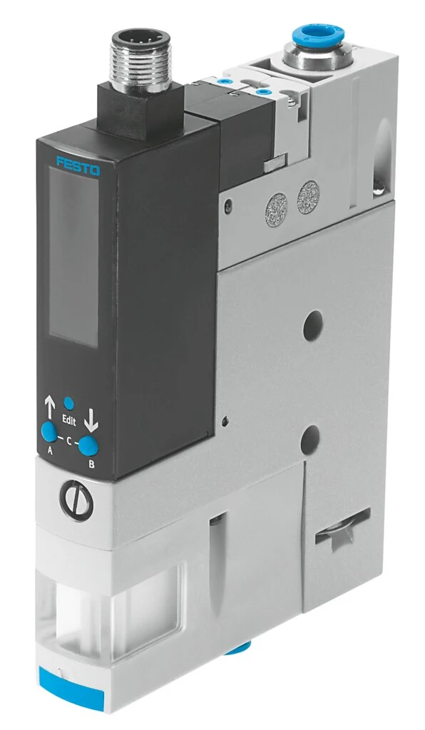
OVEL: a distributed option for low moving mass
OVEL is a compact and lightweight vacuum generator designed for dynamic, distributed handling applications. Festo’s latest product information highlights various performance levels and vacuum types, as well as integrated solenoid valves, release functions, and easy installation options. In certain configurations, it is available with IO-Link functionality for remote control or integration with robots. Placing the generator close to the gripper can reduce hose volume and response time; however, the weight at the robot end, the required electrical/pneumatic connections, and accessibility for maintenance must also be taken into consideration.
The choice between OVEM and OVEL cannot be reduced to a simple “big vs. small” comparison. Important factors to consider include the required suction flow rate, supply pressure, monitoring functions, electrical interface, installation space, weight, and cycle time. The exact nozzle dimensions and performance parameters should be obtained from the current technical specifications. Additionally, the air consumption stated in the ejector’s catalog should be converted into an annual energy consumption estimate, taking into account the actual operating efficiency of the system and its energy-saving capabilities.
ESG: modular suction cups and grippers
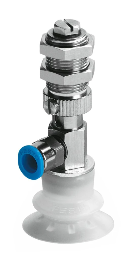
The ESG round vacuum-gripper family offers many combinations of suction-cup shape, diameter, material and mounting connection. Festo lists options such as angle compensators, height compensators and filters, with different connections and numerous variants. Match the complete ordered combination to the surface and environmental conditions, rather than specifying only the ESG family.
Flat suction cups can provide low internal volume and stable contact on smooth, flat surfaces. Curved or inclined surfaces may require compliant geometry, bellows for height differences or a swivel joint. More bellows convolutions can increase vertical compliance, while changing lateral stability and internal volume. Select cup material for temperature, oil, wear, marking and chemical compatibility. Verify food, cleanroom and sensitive-surface requirements against the exact variant documentation.
OGVM and OGGB: two approaches for challenging surfaces
OGVM is a family of connected suction cups designed for dynamic handling of products with complex contours, featuring a special anti-slip structure. According to Festo’s current product information, these cups offer high lateral forces, short suction times, and are available in round or oval shapes. These characteristics make them particularly suitable for applications where a standard suction cup would slide on the surface due to high horizontal acceleration. However, the product’s suitability must still be verified through sample tests regarding surface properties, acceleration levels, and actual safety margins.
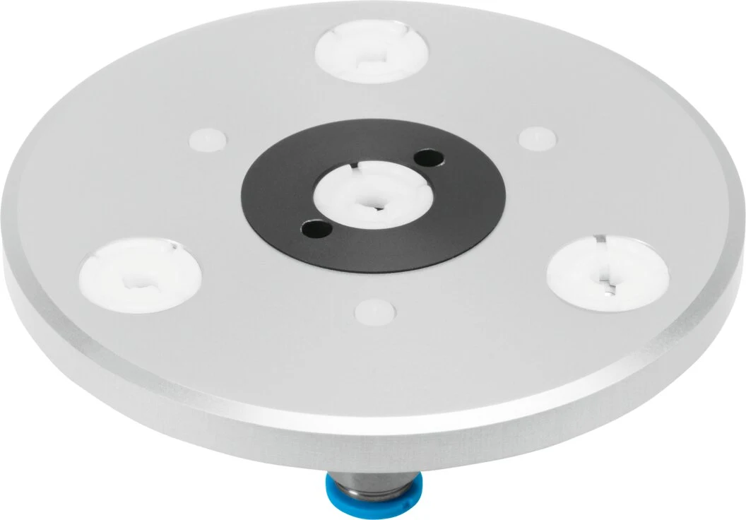
OGGB is a specialized gripper designed to handle thin, fragile, flexible, or porous components with minimal contact, based on the Bernoulli principle. The latest information on Festo’s official website clearly emphasizes its ability to minimize contact with the parts and provide gentle handling. This product should not be considered in the same way as traditional leak-proof suction cups; its performance characteristics—such as air consumption, component stability, and the distance between the gripping surfaces—must be evaluated according to the specific application. While it may offer significant advantages when handling thin sheets, electronic components, or sensitive surfaces, its edge behavior and ability to handle high accelerations must be tested in actual use with real parts.
How to choose the suction cup shape
| Part characteristic | Gripping approach to consider | Risk to monitor during testing |
|---|---|---|
| Flat, leak-proof surface | Flat, round suction cup, short hose, and appropriate diameter. | Slippage, marking, and proximity to the edge in layout arrangement. |
| Surfaces that are curved or have varying heights | Bellows suction cup, swivel joint or height compensation | Lateral oscillation, high internal volume, inclined contact |
| Long, narrow piece | Oval gripper or distributed multiple suction cups | Part rotation, uneven load distribution |
| Rough or porous surface | High leakage capacity or special gripping features. | Failing to reach the target vacuum level, continuous air consumption |
| Thin, fragile, and flexible products | Low-contact/Bernoulli approach or low pressure difference | Deformation, edge waviness, unstable handling. |
| Oil-based or rapid lateral movement | Geometry designed to enhance resistance to sliding. | Variable friction and sudden loss of parts. |
Tubing, filter and distribution design
The vacuum line should be installed as short as possible, without any compression or unnecessary connections. If the inner diameter is too small, the flow resistance and evacuation time may increase; on the other hand, if the line is too large and too long, the volume to be evacuated will also increase. The minimum bending radius must be maintained along the moving axis. When a distributor is used, the length and cross-section of the arms should be balanced accordingly. If the leakage in one gripper affects the others, a check valve or local vacuum generation systems can be considered as solutions.
The filter protects the generator and sensor from particles. Because contamination increases pressure drop, locate it accessibly and set maintenance intervals for the actual environment. OVEM’s integrated filter and inspection features simplify maintenance, but other lines must also remain clean. Hose-cutting debris, product dust or entrained liquid can cause faults. Where liquid ingestion is possible, design separation and protection before using a standard ejector arrangement.
Link vacuum monitoring thresholds to the process
A single “vacuum-ready” threshold may not be appropriate for every product. The minimum value at which a product can be safely lifted, the normal operating range, and the threshold for leakage alarms are defined separately. A time limit is set for reaching the target value after the suction command is issued; failure to meet this limit may indicate filter contamination, leakage, or incorrect contact. If the value drops below the lower limit during handling, whether the movement should continue, whether controlled release should be initiated, or whether a safe stop mechanism should be activated is determined based on a risk assessment.
During the releasing process, it is necessary to monitor the loss of vacuum and the actual separation of the components. A sticky surface, static electricity, or the use of a deep-suction nozzle may delay the component release. The adjustable ejector force should be applied in the correct amount and for the appropriate duration; excessive force may cause the small component to be knocked away. By analyzing sensor data in conjunction with the product type, minor leaks, filter clogging, and changes in the surface condition can be detected before they result in actual malfunctions.
Make energy efficiency measurable
A pneumatic ejector’s energy cost comes from compressed-air generation. Determine the optimum supply pressure from manufacturer performance curves and the actual duty instead of continuously using the highest pressure. Include nozzle size, suction time, holding time and hourly cycles in annual consumption calculations. Air-saving circuits can offer substantial savings on sealed parts; measure continuous vacuum-regeneration behavior on porous products.
Reducing leakage is often more effective than increasing pressure. Regularly check suction-cup lips, loose fittings, cracked hoses and incorrect centering. PLC logic should stop suction when production is idle. Consider activating vacuum zones only when needed. Track an energy KPI such as air consumption per part or compressor energy per defined production quantity.
Surface, material and environmental conditions
The material for the suction cup is selected based on its chemical compatibility with the product, operating temperature, wear resistance, tendency to leave marks, and hardness. Oils, separating agents, cleaning chemicals, as well as the effects of UV light or ozone, can affect the lifespan of the elastomer. When dealing with hot surfaces, not only the ambient temperature but also the contact temperature and duration of contact need to be taken into consideration. On cold surfaces, condensation can affect both sealing performance and friction.
In food or pharmaceutical applications, the presence of suitable materials in a specific variant of a product family does not necessarily mean that the entire vacuum system complies with hygienic design requirements. Cleanability, gaps, lubricants, particle generation, and all relevant specifications must be verified using the full product code. For sensitive surfaces, extensive testing is conducted on actual production samples to check for color stains, gloss, or microscopic scratches.
Test handling dynamics and vacuum performance together
The static lifting test does not represent the actual movement of a fast-moving robot. As the component accelerates in the most unfavorable direction, vacuum levels, as well as sliding and deformation phenomena, are observed. Scenarios involving sudden reversals, emergency stops, and vibrations are also tested. In the case of partial leakage in one of multiple suction cups, the load distribution is evaluated. The test set includes samples of the product with the thinnest walls, the heaviest weight, the most porous structure, and the most irregular shapes.
The robot’s path can also enhance the reliability of the gripping process. By using a smooth profile instead of abrupt accelerations, the lateral forces that cause the part to slide on the suction cup surface are reduced. An approach perpendicular to the surface at the point of grasping, along with controlled pressing, can improve sealing performance. However, excessive pressure may deform delicate products or cause the suction cup’s blades to become unstable. The approach distance and contact duration should be carefully adjusted according to the type of product specified in the recipe.
Power loss and safety
The vacuum sensor serves as a process verification component; the safety functions of the handling cell are also designed based on a risk assessment. Factors such as how long the part can be held in place in the absence of compressed air or power supply, the use of check valves and reserve volumes, as well as the protection of the drop zone and controlled stopping mechanisms, are all taken into consideration. On porous surfaces, reserve volumes may not be sufficient to ensure the desired holding time; therefore, actual component testing is essential.
Operating instructions should prohibit moving suspended loads over people, protect the drop zone and require safe release of stored vacuum during maintenance. After power restoration, do not start automatic motion until the gripping state is verified. Address separately a part remaining on the cup, released into the fixture or trapped between positions.
Commissioning and acceptance plan
- Number all product types according to their limits with regard to surface area, mass, curvature, porosity, and temperature.
- Determine the position of the suction cup based on its center of gravity and the areas providing rigid support; also monitor any changes in tolerances.
- Install the generator, hose, and filter, and measure the supply pressure during suction; perform a leakage test.
- Record suction time, lifting threshold, minimum transport vacuum and release time for each product.
- Experiment with scenarios involving rapid movement, emergency stops, partial vacuum leaks, and power outages.
- Match the vacuum value with the PLC error record and the product recipe; monitor false alarms and the rate of missed detections.
- Verify suction-cup wear, filter contamination, surface marking and air consumption over extended cycling.
Maintenance and spare parts standardisation
The suction cup is inspected for cracks, cuts, hardening, permanent deformations, and dirt. A worn-out suction cup may result in longer evacuation times and increased air consumption. The suction performance of the filter, silencer, hose, connections, and ejector is monitored regularly. Maintenance can be scheduled not only based on a calendar but also in consideration of the number of cycles and the vacuum level trend.
The spare parts list contains the complete specifications, including the suction cup shape, diameter, material, connection type, as well as any additional features such as holders and stabilizers. Elastomers that appear similar should not be substituted arbitrarily. For generators, the available variants, nozzles, electrical interfaces, valve functions, and sensor options are all recorded. The product’s lifecycle is verified on the official Festo website before placing an order; configurations listed on outdated pages are not assumed to be current.
Information required for a quotation
- Minimum and maximum mass of the product, its dimensions, center of gravity, and manufacturing tolerances.
- Surface material, roughness, porosity, curvature, holes, as well as the presence of oil and dust.
- Permitted contact area, surface trace, deformation, and cleaning requirements
- Robot orientation, maximum acceleration, emergency stop response, cycle time, and operating efficiency.
- Number and arrangement of suction cups, height differences, and the need for hinges or stabilizers.
- Target suction and release times, required monitoring thresholds, and error response mechanisms.
- Plant air pressure, quality class, available flow and annual energy target
- Central or distributed generator layout, hose length, and mobile production lines.
- PLC, digital I/O, or IO-Link interface, data recording, and recipe management.
- Power outage, risk of falling, protective area, acceptance testing, and maintenance scope.
A reliable vacuum system requires more than the largest suction cup or highest vacuum level. OVEM provides monitoring and integrated functions; OVEL supports lightweight distributed vacuum generation; ESG offers broad mechanical options; OGVM addresses dynamic surface gripping; and OGGB supports specialized low-contact handling. Oskon verifies the combination with actual product samples, motion profiles, energy calculations and fault scenarios, then confirms the selection against the current Festo configuration and exact variant documentation.
Official Festo resources
- Festo — Product category for vacuum technology
- Festo – OVEM vacuum generator
- Festo – OVEL vacuum generator
- Festo — ESG circular vacuum gripper
- Festo — Suction cups connected via OGVM.
- Festo — OGGB Bernoulli gripper
- Festo — OVEM technical documentation (version 2026)
- Festo – OVEL technical documentation (version 2026)
- Festo — ESG Technical Documentation (Version 2026)
- Festo — OGGB Technical Documentation (Version 2026)