“3D-MID expertise” and “special-purpose machinery manufacturing” are two distinct areas of competence within HARTING, although they do not belong to the same product family. HARTING AG in Switzerland is dedicated to the development and mass production of customized mechatronic components that integrate electronic and mechanical functions on a three-dimensional substrate. HARTING Applied Technologies, on the other hand, designs and manufactures mounting fixtures, semi-automatic workstations, and fully automated assembly systems. These two areas may sometimes overlap in a single project, but it should not be assumed that every 3D-MID component is accompanied by a special-purpose machine, nor that every machine produced by HARTING Applied Technologies is used for 3D-MID production.
This design guide defines these two concepts within clear boundaries and establishes a possible relationship between them based on the aspect of productivity. In the context of 3D-MID, considerations include component geometry, materials, conductive pathways, electronic components, manufacturing processes, and quality verification; whereas for specialized machinery, aspects such as product feeding, assembly, measurement, testing, robotics, control software, data collection, and acceptance criteria are defined. The technical specifications and material values mentioned in the text apply solely to the standard 3D-MID carrier products referenced. The performance of custom components or machinery cannot be derived from these examples without conducting a thorough analysis of actual requirements and conducting corresponding verification.
What 3D-MID is and what it is not
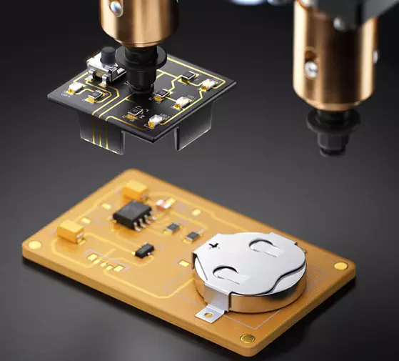
According to HARTING’s official statement, 3D-MID refers to the integration of electronic and mechanical functions on a three-dimensional base structure, using the concept of “mechatronic integrated devices.” Unlike traditional flat circuit boards, where conductive traces are limited to a single plane, in 3D-MID, these traces can extend across multiple surfaces of the component. Moreover, the base structure itself can perform functions such as mechanical positioning, mounting, or protection. This approach offers significant advantages in terms of design flexibility, miniaturization, weight reduction, functional integration, and the potential to streamline production processes. However, it’s important to note that transforming any flat circuit board into a three-dimensional component does not necessarily result in automatically smaller, cheaper, or more reliable products.
3D-MID is not synonymous with three-dimensional printing; nor is it merely the addition of conductors to a decorative plastic shape. The carrier material, molding method, metallization process, geometry of the conductive paths, surface coating, component assembly, and end-use environment must all be carefully coordinated with one another. On its official website, HARTING Switzerland states that it carries out the entire 3D-MID process chain – from the initial concept to prototype development and finally to the verification of mass-production suitability – in the same location. Such integration can accelerate the feedback cycle between different stages of the process. However, the specific requirements of each customer project, including dimensions, tolerances, testing criteria, and investment objectives, are always assessed individually.
Define product requirements before drawing conductive tracks
A 3D-MID project should begin by defining the functional requirements and boundary conditions, rather than simply creating a CAD model. The mechanical functions of the component within the device, its connection points, target external dimensions, mounting references, as well as static and dynamic loads, operating temperature, humidity, chemical exposure, vibration levels, and expected lifespan must all be taken into account. On the electrical aspect, parameters such as voltage, current, frequency, signal integrity, insulation requirements, creepage/clearance specifications, RF behavior, and ESD/EMC compliance targets need to be determined. Additionally, the list of components, packaging requirements, heat dissipation considerations, the process of soldering or other forms of connection, and test accessibility for the same model must all be evaluated.
The three-dimensional path, the part separation line, the sharp corners, the movement of the mold, the laser access area, and the approach of the mounting head must not overlap. A component cannot be automatically placed on a sloped or narrow surface merely because it is compatible with the electrical schematic. The availability of feeding mechanisms, holding devices, coating or adhesive application systems, soldering/bonding processes, and optical inspection capabilities limits the design options in production. As the production volume increases, cycle time and the use of multi-cavity systems become more important; however, for small production volumes, investing in molds and fixtures can create a different economic balance. Therefore, part design, process engineering, and automation evaluation should be carried out in conjunction from an early stage.
The process chain and quality window
HARTING’s Swiss sources refer to an in-house process chain for 3D-MID that includes steps such as molding, laser processing, chemical metalization, component placement, as well as techniques like EOP/AOI. The specific methods employed depend on the component and the materials used. In a process that utilizes laser direct structuring, the appropriate additive polymers are selectively activated using a laser; metalization is then carried out to create conductive pathways. Other designs may require different structuring or coating approaches. The term “3D-MID” does not imply a fixed, universal manufacturing process.
The quality plan defines the input parameters and acceptance criteria for each step of the process. During molding, dimensions, deformation, and surface quality are inspected; during structuring, the position and width of conductive traces are verified; in the metallization process, thickness, adhesion, and continuity are checked; and during final electrical testing, not only short-circuit/open-circuit checks are performed, but also sensor accuracy, RF performance, temperature stability, and functional tests may be required. A measurement system qualification process and a reference sample strategy must be established before starting mass production.
Standard 3D-MID carriers as a practical technology example
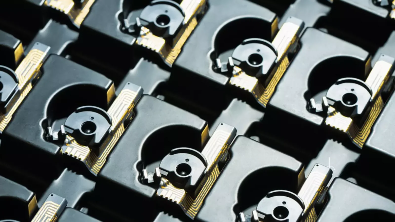
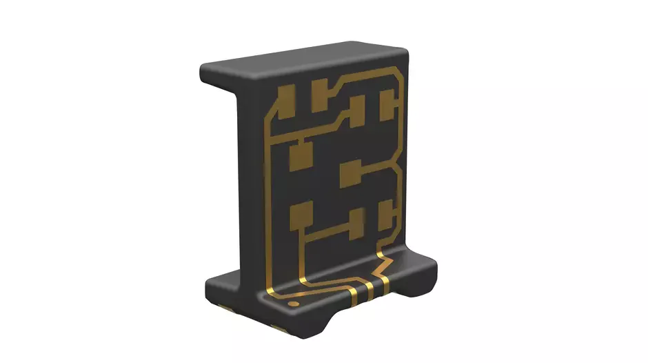
HARTING’s Carrier_BT807042_SOT23-3_v, 78 01 030 0011 The product page describes a small component carrier belonging to the 3D-MID category. This product is defined as an electronic component carrier designed for SMD circuit board mounting, made of PPA material, and featuring three-dimensional connections. For this specific order number, the dimensions are specified as 8 × 7 × 4.2 mm, and the operating and storage temperature range is −40 to +125 °C. The contact surfaces are coated with nickel and gold layers on a copper base, as detailed on the product page; the packaging method is described as “tape & reel”.
This standard carrier does not imply that all customer-specific 3D-MID projects must use the same PPA material, the same temperature range, or the same coating thickness. The HARTING product page indicates that other materials or pattern arrangements may be possible upon request; however, such options require additional verification rather than automatic compatibility checks. It is also necessary to consider factors such as the solder pad layout on the PCB, the thermal profile, mechanical support, and the desired service life of the component. While the illustration in the image helps to understand the technical principles, it cannot replace the actual design considerations for a sensor, antenna, or device enclosure project.
Special-purpose machinery manufacturing is a separate capability
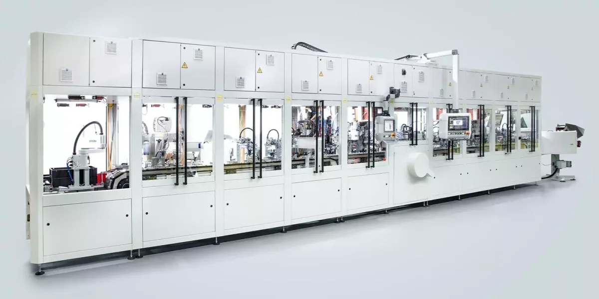
HARTING Applied Technologies is a separate division of HARTING that specializes in the conceptualization, development, and manufacturing of complex specialized machinery for assembly technology. According to its official product portfolio, its offerings include assembly fixtures, semi-automatic assembly workstations, and fully automated assembly plants. These machines are not designed specifically for HARTING connectors or 3D-MID components alone; rather, they are tailored to meet the requirements of customers in various industries. As a result, selecting HARTING Applied Technologies’ solutions is not as straightforward as choosing a standard “machine model.” Instead, it requires initiating a project based on a detailed specification that takes into account the product requirements, manufacturing process, capacity, quality standards, and operational conditions.
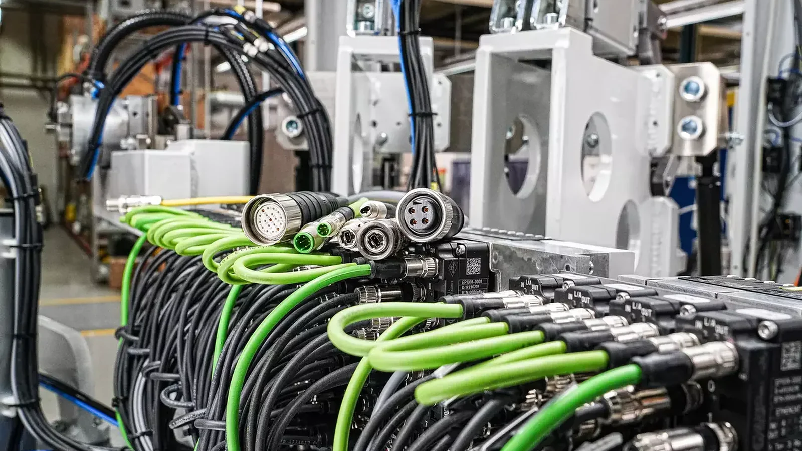
The scope of applications includes handling systems such as articulated robots, SCARA robots, axis portal systems, and pneumatic pick-and-place devices; as well as plant configurations like rotary indexing systems, linear indexing systems, workpiece carriers, and associated conveyor lines. On the feeding side, vibrating or spiral feeders, hoppers, linear conveyors, bin picking systems, and other sorting methods can be used. The processes applied range from image processing to pressure/leakage testing, electrical measurement, laser marking, bonding, welding, pressing, packaging, and various other assembly steps. These are just some of the available options; the specific processes included in a particular machine are determined based on the customer’s product requirements and acceptance criteria.
How can these capabilities work together in one project?
The common denominator is “designing the product in conjunction with a producible manufacturing process.” For example, if a custom 3D-MID sensor carrier is to be molded, metalized, assembled, then installed in a enclosure, and subsequently tested and labeled electrically, specialized automation will be required for these consecutive steps. A machine with capabilities similar to those of Applied Technologies could handle tasks such as part feeding, precise positioning, robotic assembly, camera monitoring, electrical testing, and data recording. However, such an arrangement is determined solely within the context of a specific project and is not an inherent or essential part of 3D-MID services.
A common interface document should be established between the product team and the machine team. The datum points of the component, its gripping surfaces, sensitive areas, acceptable tolerances, test points, coding areas, and permitted contact forces serve as inputs for machine design. In turn, the machine can influence the product design through feedback regarding feeding directions, gripping repeatability, cycle times, and optical accessibility. This two-way communication can help minimize the need for complex additional fixtures or unreachable test points. Separate validation plans should be maintained for both the final product performance and the machine’s operational efficiency.
Requirements management and concept comparison
HARTING Applied Technologies’ approach to customer projects defines the sales, development, order execution, and service phases as coordinated steps. The official website explains that a detailed project plan is prepared before submitting a quote, and the customer’s early involvement in the conceptual phase, along with the project manager’s role throughout the approval process, are key elements of this approach. The model-based systems engineering approach aims to establish a clear link between the product, its production environment, functional processes, and technical solutions. This method is particularly useful for managing the impact of product variations, automation levels, and subsequent changes.
In the conceptual phase, manual, semi-automatic, and fully automatic options should be compared using the same set of data. Factors such as annual volume, shift scheduling, target cycle time, product mix, replacement frequency, error cost, operator ergonomics, and investment limitations should be carefully considered. High levels of automation are not always the best solution; in cases of frequent product variations or low production volumes, more flexible systems may be more appropriate. On the other hand, for processes where quality depends critically on measurements of force, distance, or electrical parameters, automated processes and data recording are essential. The decision should take into account not only the initial investment but also the costs associated with commissioning, maintenance, spare parts, space requirements, energy consumption, and the entire product lifecycle.
Modularity, FAT/SAT and lifecycle
Applied Technologies states that cell-based modular design can help in gradually expanding capacity, adapting to various environmental conditions, and facilitating retrofitting applications. Modularity truly delivers its benefits only when mechanical, electrical, software, safety, and data interfaces are all well-defined. The independent cycle behavior and fault characteristics of each cell must be simulated, taking into account any buffering mechanisms and potential bottlenecks in the upper-level transportation system. For any additional stations that may be added in the future, not only sufficient floor space but also power supplies, air supply systems, network connections, safety areas, and control capabilities must be reserved.
During the factory acceptance test, the original product or a representative sample is subjected to extended-cycle tests to evaluate its capacity, waste generation, measurement systems, error scenarios, recipe variations, and safety functions. Separately testing complex modules can help reduce installation risks. After the machine is transported to the site, a SAT is conducted under actual production conditions, including plant connections. A successful FAT does not automatically guarantee SAT acceptance; factors such as the floor conditions, power quality, network infrastructure, the surrounding environment, and operator interaction must be re-verified. Training programs, maintenance plans, spare parts, software backups, and as-built documentation should all be included as measurable elements of the delivery scope.
Machine data and traceability
Applied Technologies’ official approach to machine data collection involves the real-time collection of information on order status, measured values, maintenance activities, cycle time, operating duration, faults, output data, and machine status. The described architecture is based on a combination of Beckhoff controllers, OPC UA servers, and databases; however, this technical configuration is merely an example implementation and is not mandatory for every specific application. Additionally, factors such as which tags to record, the sampling frequency, the source of timestamps, the data retention period, and user permissions must also be determined for each project.
If automation is implemented in 3D-MID production, the part serial number can be linked to information such as the molding batch, the metallization recipe, the assembly results, camera images, and electrical test results. This facilitates the identification of the root causes of any process deviations. However, data collection alone is not sufficient for ensuring quality. It is also necessary to calibrate sensors, analyze the measurement systems, monitor the error acceptance/rejection rates, ensure data integrity, and establish proper backup procedures. Changes to the manufacturing recipes must be authorized, and product revisions as well as machine software updates should be tracked within the same production record system.
| Topic | 3D-MID project | Special-purpose machinery project | Shared verification point |
|---|---|---|---|
| Main output | Three-dimensional mechatronic carriers or integrated components | A customer-specific facility for assembly, measurement, and testing. | Product and process interface specification |
| Basic inputs | Geometry, material, conductive path, component, environment, and volume. | Product, cycle, variant, feeding, process, and quality objective | Datum, gripping, test access, and tolerances. |
| Technical risks | Metalization, adhesion, thermal/EMC properties, and accessibility for assembly. | Bottlenecks, feeding stability, measurement, safety, and changeover | Manufacturability and measurable acceptance criteria |
| Prototype/acceptance | Samples, material-process suitability, and product testing | Module testing, FAT, on-site SAT, and capacity testing. | Representative products and traceable test data |
| Life cycle | Management of material, tool, coating, and product revisions | Maintenance, spare parts, software, services, and retrofitting. | Monitoring the impact of the change on both parties |
Data required for quotations and feasibility studies
- Separate these into two categories: Clearly state whether the desired output is a 3D-MID component, a special-purpose machine, or a combination of both.
- Describe the product’s function: Share mechanical specifications, electrical circuits, signal/RF characteristics, components, as well as dimensions and tolerances.
- Specify the environment and lifespan: List the targets regarding temperature, humidity, chemicals, vibration, impact, cycle time, and regulatory requirements.
- Provide the production volume: Describe the prototype, annual production volume, shift system, product lifespan, batch size, and expected variations.
- Extract the process flow: List the steps involved in the process, from the assembly of raw components to the packaging of the final product, including mounting, joining, marking, measuring, and testing.
- Let’s discuss the level of automation: Compare manual, semi-automatic, and fully automatic options in terms of cycle time, quality, ergonomics, and investment costs.
- Display the interfaces: Mark part datums, gripping areas, sensitive surfaces, test pads, feeding direction, and permissible forces in CAD.
- Quantify quality criteria: Specify tolerances, test limits, measurement uncertainties, incorrect acceptance/rejection criteria, sample requirements, and traceability conditions.
- Plan for FAT and SAT: Describe the representative product, the required capacity over time, potential error scenarios, training requirements, documentation, and on-site acceptance criteria.
- Include the life cycle in the contract: Clarify the responsibilities regarding tool maintenance, spare parts, software backups, remote access, as well as modifications and retrofits.
Oskon addresses these two HARTING competencies without merging them under a single general product label. The 3D-MID approach focuses on component and process technology, while the special-purpose machinery approach aims at enabling the repeatable assembly, measurement, and testing of this or another product. When these approaches are combined within the same project, success relies on early feasibility studies and mutually agreed-upon criteria. The final scope, technical feasibility, investment details, and timeline information must also be confirmed in the project proposal; this guide does not constitute any commitment regarding standard machinery, stock availability, or a specific 3D-MID outcome.