In areas where there is a possibility of the presence of explosive gases or flammable dust, the selection of control panels goes beyond merely choosing a conventional enclosure. Factors such as the area classification, protection method, equipment group, temperature class, ambient temperature, cable connections, terminals, and total thermal loss are all components of the same compliance framework. Within Tempa Pano’s Ex-proof product range, the TES and TEX series are available. The manufacturer’s official technical documentation specifies these enclosures for use in Ex e and Ex ia applications, in Gas Zones 1 and 2, and in Dust Zones 21 and 22. This guide catalog explains their mechanical characteristics and selection procedures; however, it does not replace the actual classification of hazardous areas within a particular facility or the comprehensive compliance assessment of the selected control panel.
Material and enclosure characteristics of the TES and TEX series
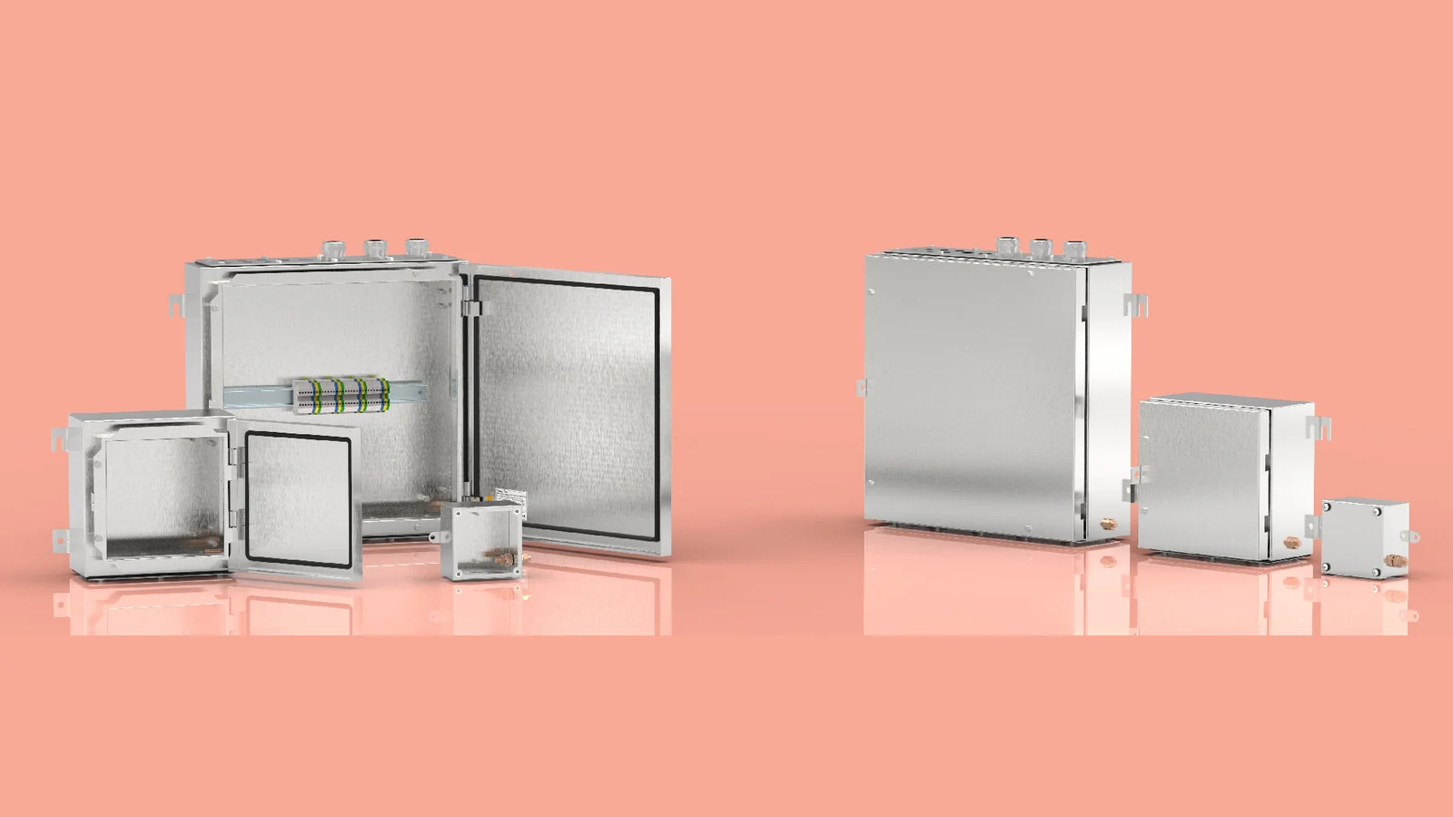
According to the Tempa TES/TEX product page, the body and the cover or door are made of 316L stainless steel in accordance with the EN 10088 1.4404 standard. The thickness of the body and door sheets is 1.2 or 1.5 mm, depending on the product size. The TEX standard specifies that the cable passage plate has a thickness of 2 mm; a mounting plate is also available as an additional accessory. The surface is treated with Scotch-Brite brushing and is made of stainless steel, with a protection class of IP66 as per TS 3033 and EN 60529 standards. The temperature range for the polyurethane molded seal around the closure is specified as −40…+100 °C.
Although TES and TEX belong to the same family of certified products, their standard designs are not identical. In the dimension table, the smaller TES models feature a lid that is secured with screws and lack hinge plates or cable pass-through sections. TEX models, on the other hand, are equipped with a 2-mm cable pass-through plate and two or three hinges, depending on the product size. The product family description specifies that the hidden hinges allow 180-degree opening and closing, and that the screws used are non-detachable. Therefore, the choice of lid, door, hinge type, and cable entry configuration must be confirmed based on the selected product code.
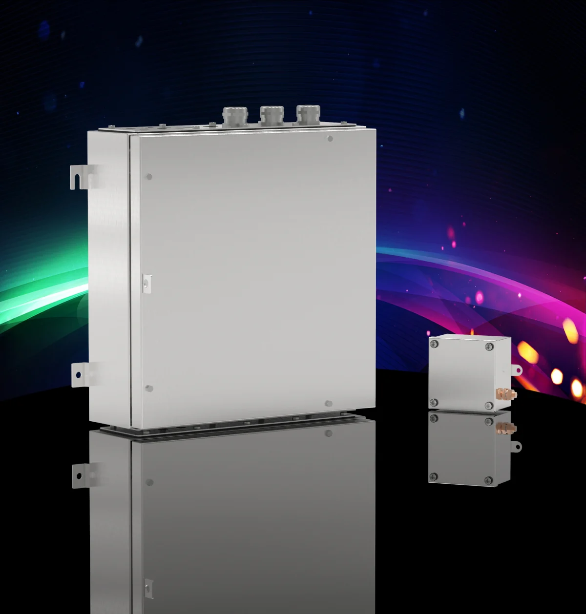
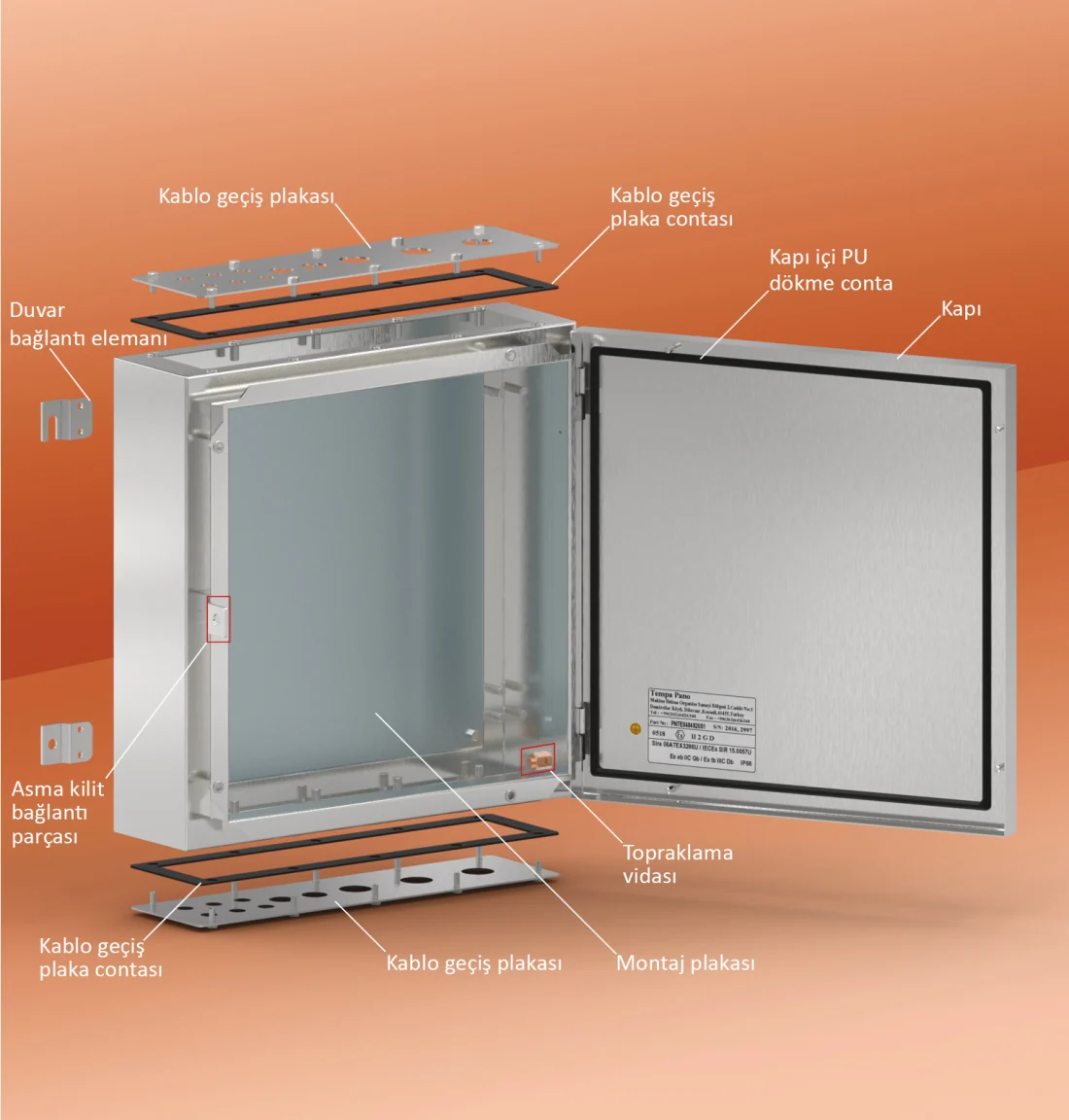
The impact resistance of this series is specified in the official documentation as 7 joules. The enclosure includes integrated M6 and M10 grounding points both inside and outside the body. The standard equipment includes the enclosure body, cover or door, grounding screws, and wall mounting components. Additional accessories such as mounting plates, DIN rails, grounding conductors, and horizontal or vertical DIN rail connectors are available upon request. The number and placement of cable pass-through plates must be confirmed with the manufacturer based on the selected product code and the scope of the Ex certification; special dimensions, custom mounting plates, and galvanized and painted versions are also subject to this verification process. It is essential to ensure that each customized configuration is not only mechanically feasible to produce but also complies with the selected Ex marking and certification requirements.
Consider the zone and protection method together
The Tempa document classifies TES/TEX components as follows: for gas environments, they are designated as Zone 1 Category 2 or Zone 2 Category 3; for dusty environments, they are classified as Zone 21 or Zone 22. The same document also specifies applications suitable for Ex e or Ex ia configurations, depending on whether the terminals are arranged horizontally or vertically. Ex e represents an increased safety approach, while Ex ia denotes an intrinsically safe circuit design. However, these designations do not imply that any component installed in an empty enclosure is automatically suitable for the specified application. The type of terminals, circuit classification, cable glands, blind caps, internal connections, separation distances, marking requirements, target zone, and protection methods must all be carefully selected to ensure compliance. The initial data for a project should include a hazard classification prepared by a qualified expert.
IP66 protection and Ex conformity are different concepts
The IP66 rating indicates the degree of protection the enclosure provides against solid objects and water intrusion; the Ex compliance, on the other hand, represents a set of additional and more comprehensive requirements designed to mitigate the risk of ignition. On TES/TEX labels, both these information items are listed, but they cannot be used interchangeably. Proper sealing of the cover or door gaskets, screws, cable entries, and any unused openings is essential for ensuring the integrity of the IP protection. In addition to these requirements, Ex certification also involves certified entrance components, appropriate terminal arrangements, temperature limits, protective connections, and specific certification conditions. Therefore, specifying merely “IP66 stainless steel enclosure” in a specification document is insufficient to accurately define the required protection level for a hazardous area. It is necessary to also specify the desired Ex protection method, the zone classification, the gas or dust group, the temperature class, and the environmental conditions.
Temperature class and ambient temperature
On the manufacturer’s product page, the ambient temperature range for T5 is specified as −40…+55 °C, while for T6 it is −40…+40 °C. The official documentation states that the maximum surface temperature for T6 class equipment is 85 °C, and for T5 class equipment it is 100 °C. These two figures are different: the ambient temperature refers to the surrounding conditions in which the enclosure is located, whereas the temperature class defines the maximum allowable surface temperature of the equipment. The heat generated by the internal components and connections must be taken into account together with the external ambient temperature. If a project exceeds the environmental limits specified in the catalog, it should not be assumed that the standard configuration is suitable; instead, a specialized assessment should be conducted in consultation with the manufacturer and relevant compliance documentation.
Thermal load calculation for terminal boxes
Tempa’s technical data sheet for TES/TEX products states that the maximum allowable heat dissipation for each enclosure depends on the ambient temperature and the temperature class of the application. The fundamental formula for calculating power loss in terminals and connections is P = I² × (Rt + Rc), where I represents the circuit current, Rt the electrical resistance of the terminal, and Rc the resistance of the connection or conductor. The total calculated power loss for each circuit is then summed and compared with the maximum allowable value specified for the selected enclosure. According to the document’s guidelines, if the total load percentage exceeds 100%, a larger enclosure must be selected and the calculation repeated to ensure that the external dimensions are determined not only by the number of terminals but also by the allowable thermal capacity.
For this calculation, it is necessary to use the current and resistance data provided by the terminal manufacturer, the actual circuit currents, the connection layout, the target T-class rating, and the maximum ambient temperature. When choosing between horizontal or vertical terminal arrangements, the required cable bending space and separation requirements must also be taken into account. The fact that “the terminals fit physically” does not constitute sufficient proof of thermal compatibility. Similarly, merely adding up the nominal currents does not provide a reliable assessment, due to the influence of the I² relationship. The Pmax value corresponding to the relevant body size specified in the catalog must be used; the calculation results should be recorded in the project documentation and verified against the actual terminal components selected. Any changes to the circuit or terminals must also be accompanied by a reevaluation of the thermal performance.
Certification and marking scope
Tempa’s official catalog for the TES/TEX series includes the following certifications: IECEx SIR 15.0056X for equipment, with ratings Ex eb IIC T6 Gb and Ex tb IIIC T57°C Db, IP66; and IECEx SIR 15.0057U for components. The same catalog also contains information on SIRA 06 ATEX 3285X and SIRA 06 ATEX 3286U certifications for ATEX compliance; CSAE 22 UKEX 1136X and CSAE 22 UKEX 1135U certifications for UKCA compliance. Standards EN IEC 60079-0, EN IEC 60079-7, EN 60079-11, and EN 60079-31 are also referenced in the catalog. It is important to verify the product label, certification revision, and specific usage conditions based on the latest documentation when placing an order. The ratings listed for a particular series in the catalog should not be assumed to apply unconditionally to all individual applications.
Distinguishing the “X” and “U” suffixes at quotation stage
The “X” at the end of the certification number indicates that special conditions are required for safe use; the “U” symbol, on the other hand, signifies that the product is an Ex-component. A component certificate does not imply that the part can be used directly as a complete device supplied to the end-user. When terminals, cable glands, and other components are installed inside the enclosure, the resulting assembly must be evaluated in accordance with the intended protection method and must include the necessary markings and documentation. Therefore, the tender document must clearly specify whether an empty enclosure, a component-ready box, or a fully equipped unit with terminals and connectors is required. The scope and special conditions of the relevant certification must be carefully reviewed by a qualified individual before the product is selected.
Cable entries and mechanical preparation
The number and placement of cable pass-through plates provided upon request must be confirmed with the manufacturer in accordance with the selected TES or TEX product code and the scope of the certification. Every hole and entrance in a hazardous area is an integral part of the protective system. It is essential to verify that the connectors and blind caps comply with the relevant Ex protection classification, IP rating, cable outer diameter, and environmental conditions. The hole diameter, thread type, edge distance, and position of the plates must be accurately indicated in the approved drawings. Instead of making random holes on-site, it is more reliable to choose from the pre-treated options or custom plates available upon request, in line with the certification specifications. Unused entrances should be closed with appropriate sealing elements, and the clamping requirements specified in the installation instructions must be followed.
| Selection data | Official technical information for TES/TEX | Point to verify in the project |
|---|---|---|
| Materials | 316L, EN 10088 1.4404 | Compatibility with ambient and accessory materials |
| Protection | IP66 | Integrity of entrance components and closures |
| Areas | Zone 1/2 and Zone 21/22 | Facility hazardous-area classification by an authorized specialist |
| Protection methods | Ex e and Ex ia applications | Circuit, terminal, and wiring layout |
| Ambient temperature | T5: −40…+55 °C; T6: −40…+40 °C | Actual minimum and maximum field temperatures |
| Thermal control | P = I² × (Rt + Rc); the total load ≤ Pmax. | Actual component data and the selected body size. |
Commissioning and maintenance documentation
Once the installation is complete, the product label and certification number, series and model code, mounting direction, all fastening screws, gasket surfaces, grounding connections, cable glands, blind caps, and any unused openings must be inspected. The terminal clamping values must be set in accordance with the manufacturer’s instructions for the relevant components and recorded accordingly. Electrical details such as cable shielding or intrinsically safe circuit separation must comply with the project specifications. The thermal load calculation, terminal list, cable routing diagram, certifications, special operating conditions, and maintenance instructions should all be included in the same technical documentation. During maintenance, only replacement parts of equivalent quality must be used; any modifications that alter the gasket, screw, surface, or connection layout must be reevaluated for compliance.
Data to prepare before requesting a quotation
For the correct selection of TES/TEX configurations, it is necessary to provide information regarding the gas or dust environment, the applicable zone, the type of equipment, the desired protection method, the temperature class, the maximum and minimum ambient temperatures, the external dimensions, the types of terminals, the circuit currents, the number and diameter of cables, the thread specifications of cable glands, the input surfaces, the requirement for a mounting plate or DIN rail, as well as the wall mounting layout. The desired certification for the application should also be specified. The box should not be selected solely based on the number of terminals without conducting a thorough thermal calculation. The specific requirements listed in the manufacturer’s current catalog and certification documents must be matched with the order code. This approach ensures that robust enclosure materials such as 316L stainless steel and IP66 protection are combined with an appropriate Ex design, thereby clarifying the responsibilities and certification requirements for the completed control panel.