The reliability of an electrical or automation control panel is not determined solely by the quality of the devices contained within it. Drives, power supplies, contactors, PLC hardware, and other electronic components generate heat during operation; moreover, dust, moisture, and oil vapor in the surrounding air also affect the conditions inside the panel. When the internal temperature exceeds the recommended operating range, the risk of unexpected downtime, reduced lifespan, and unstable performance increases significantly. Tempa Pano’s climate control solutions combine TCY panel air conditioners with fan and filtration systems within the same product range, enabling effective management of these factors.
This catalog guide does not simply categorize products as “coolers” or “fans”; instead, it explains how to select the right solution based on the specific project requirements. It distinguishes between applications that require closed-loop cooling in dirty or hot environments and those that can be adequately served by filtered ambient air. Factors such as panel size, total heat loss, target internal temperature, external conditions, protection class, and maintenance requirements are all taken into consideration. As a result, the air conditioning equipment becomes a measurable and integral part of the panel design, rather than an additional accessory added later on.
Start climate control selection with the operating environment
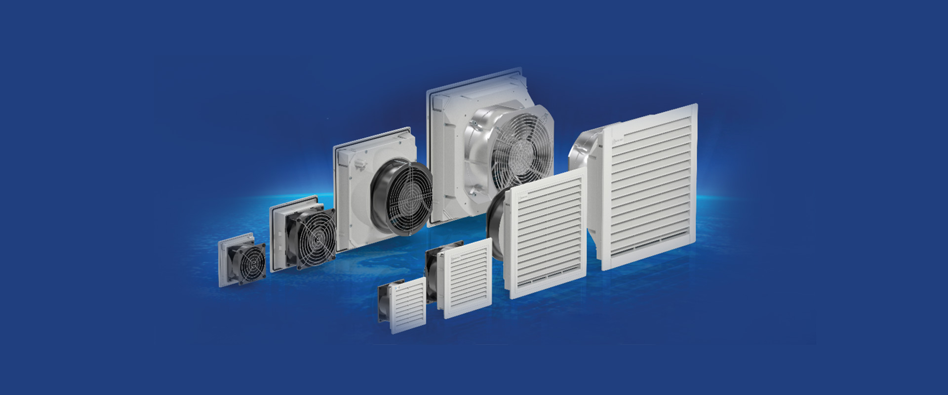
The first decision to make is whether it is appropriate to introduce outside air into the control panel. If the ambient temperature is lower than the desired internal temperature, the air is clean enough, and filter maintenance can be carried out regularly, then a fan-filter system can be a cost-effective and straightforward solution. The fan draws in cooler air from the lower area, while the outlet filter on the other side helps to remove the heated air. The air flow rate is determined not only by the volume of the control panel but also by the continuous heat generated inside it and the allowable temperature difference.
When the external environment is extremely hot, contains dense dust or oil aerosols, or when it is necessary to isolate the air inside the control panel from the surrounding environment, a closed-loop control panel cooling system becomes the preferred solution. The TCY series represents such a solution, designed to dissipate heat without mixing the air inside and outside the panel. When making this selection, factors such as the cooling capacity, the amount of fresh air available to the condenser, the mounting dimensions, electrical power supply requirements, the door’s load-bearing capacity, and the drainage system for condensate are all taken into consideration.
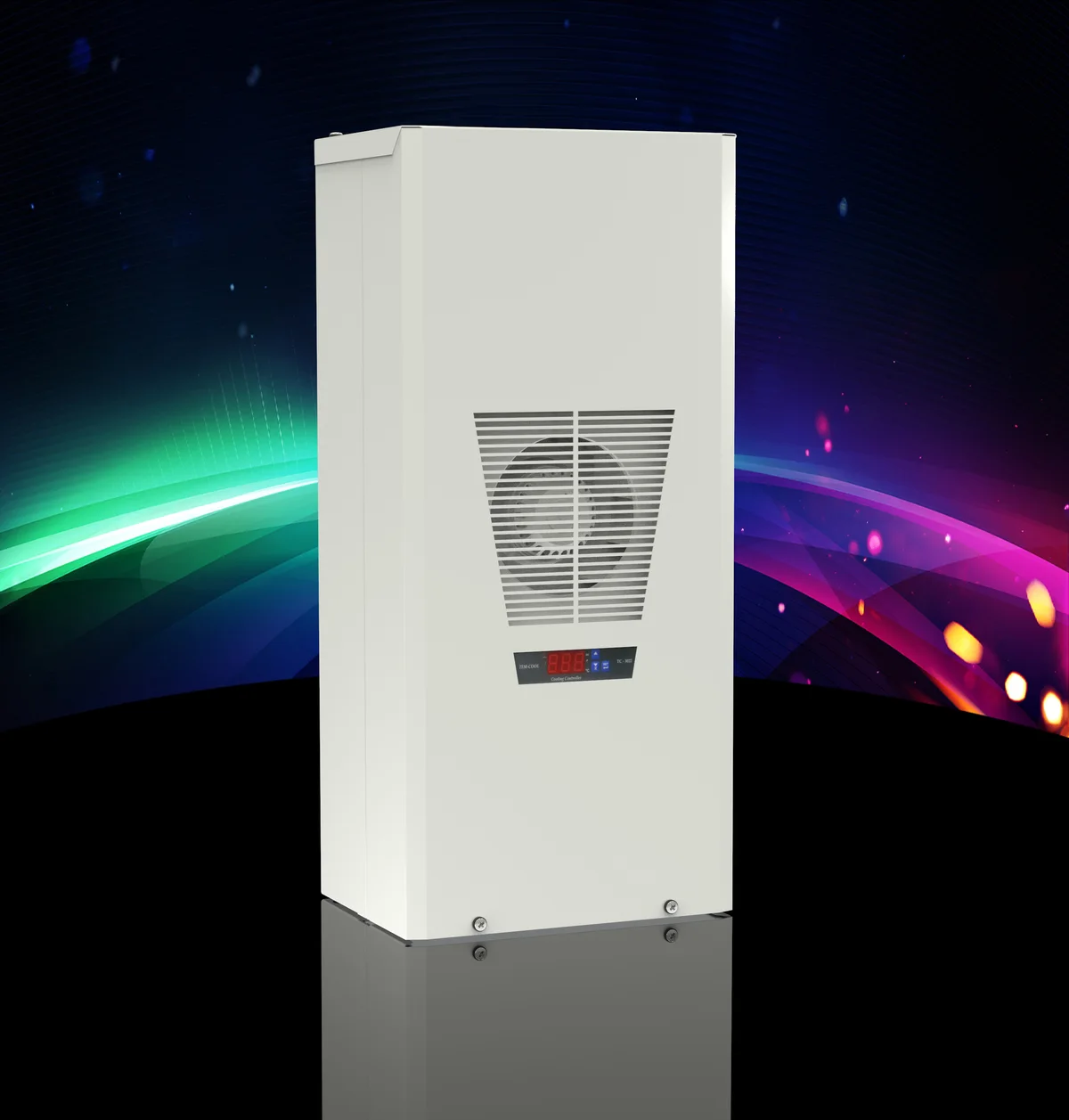
Construction features of the TCY series
On Tempa Pano’s official product page for TCY, it is specified that the body is made of 1.2-mm steel, while the galvanized mounting plates are made of 1.5-mm sheet metal. The outer surface is painted with RAL 7035 electrostatic paint. For the product to form a durable whole within the control panel environment, the design of the body, the connection surfaces, and the sealing arrangements are all crucial. If the unit is intended to be installed on the control panel door or side, the stiffness of the sheet metal, its center of gravity, the load on the hinges, and the potential for vibration effects must all be carefully considered during the design phase.
For TCY products, the degree of protection is specified separately for both sides of the device: the control panel side meets the IP54 standard, while the exterior side meets the IP34 standard. Both values are based on the references TS 3033 and EN 60529. Since the cutout design, gasket installation, and assembly procedures directly affect the final level of protection provided by the control panel, the choice of protective specifications should not be summarized merely by stating “IP54-rated device.” The mounting surface must be flat, the gaskets must be properly sealed, and the cable entrances must be securely closed. The initial protection class of the control panel is not the same as the final protection level of the entire system after the air-conditioning device is installed. It is essential to remove any excess material from the cutout, protect the exposed metal surfaces from corrosion, and ensure that the assembly is carried out in accordance with the manufacturer’s current specifications.
The digital control structure of the TCY facilitates the adjustment of the target temperature and the monitoring of its operating status. Programmable door or alarm contacts enable the transfer of climate control-related information to the panel automation system. These contacts can be connected to a PLC input, an alarm circuit, or a remote monitoring system. The alarm logic must be clearly defined in the design: it is essential to specify how events such as high temperatures, open doors, or device failures should be communicated to the operator, and under what circumstances a controlled shutdown should be initiated.
Capacity ranges and flexibility within the same cut-out
The current Tempa catalog lists seven product classes: TCY0500, TCY0700, TCY0900, TCY1500, TCY2000, TCY3000, and TCY4000. The cooling capacities specified in the catalog for an enclosure internal temperature of 35°C and an ambient temperature of 35°C are 500, 700, 900, 1500, 2000, 3200, and 4350 watts, respectively. These figures serve as reference values for comparing different capacity classes and should not be interpreted as absolute indicators of field performance. The actual cooling capacity should be assessed based on the differences between enclosure internal and ambient temperatures, the operating point, and the specific capacity curves of the product. When making a final product selection, it is also essential to refer to the manufacturer’s latest electrical data.
Providing two power options for the same mounting configuration in a series is valuable for projects where thermal requirements vary, as it facilitates mechanical standardization. The same body family or recurring machine modules can use the same mounting cutout; however, transitioning to a higher capacity cannot be determined solely by physical compatibility. Power supply, fuses, cable dimensions, initial startup behavior, weight, and air circulation must all be reevaluated. While the standard mounting cutout approach simplifies the selection of spare parts and maintenance plans, it does not replace the need for thorough engineering validation.
| Solution family | Typical suitable conditions | Item to check in the project |
|---|---|---|
| TCY control panel climate control system | When the external environment is hot or dirty, or when the air inside the control panel needs to be separated from the surrounding environment. | Thermal load, operating point, mounting cross-section, power supply, condensation, and alarm system. |
| Fan-filter units | The outdoor air temperature is lower than the desired indoor temperature and is suitable for passing through the ambient filter. | Required flow rate, inlet/outlet positions, filter class, pressure loss, and maintenance intervals. |
| Only passive ventilation. | Very low thermal load and favorable environmental conditions. | Natural convection, louvered areas, protection levels, and temperature verification. |
Wide fin spacing and maintenance of the ambient-air side
In the product specifications of TCY, a wider fin spacing is one of the features highlighted in terms of maintenance and air flow. Dust accumulating on the condenser surface can reduce heat transfer efficiency and air flow rate, thereby diminishing cooling performance. While a larger spacing between the fins helps delay the effects of contamination, it does not eliminate the need for cleaning. The frequency of maintenance should be determined based on the dust accumulation in the system, either through visual inspection, pressure difference measurements, or performance monitoring.
The optional dust filter available for the external fan helps protect the condenser in dirty industrial environments. Since the addition of a filter may cause pressure losses in the airflow, it is not sufficient to simply install it physically; instead, it must be considered in conjunction with the manufacturer’s recommendations and maintenance guidelines. A clogged filter is not more protective than a clean one—it reduces air flow, increases the compressor’s running time, and may increase the risk of high temperatures. Maintenance procedures must clearly specify the criteria for checking, cleaning, or replacing the filter, as well as the team responsible for these tasks.
Condensate drainage and water management
When the humid air inside the control panel is cooled, condensation may form. The condensation drainage system specified in the TCY series provides a design solution to ensure that the resulting water is removed in a controlled manner. The drainage duct must be arranged in a continuously downward slope to prevent water from accumulating and causing backpressure. The end of the duct must not allow water to drip onto the panel base, electrical connections, or walkways; instead, the water should be directed to an appropriate drainage point in the facility.
If the doors remain open for an extended period, hot and humid outdoor air will enter the control panel, potentially causing additional condensation after the doors are closed. In such cases, a programmable door contact can be incorporated into the system’s operating or alarm protocols. It is also necessary to inspect the panel’s cable entrances, sealing gaskets, and any unused openings. The air conditioning unit will not compensate for issues such as faulty cable glands, damaged seals, or open spaces at the base of the unit that may lead to water ingress.
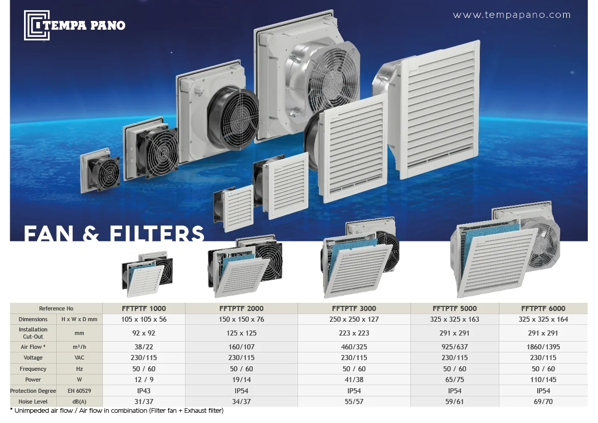
Design the correct airflow path through the fan and filter system
In fan-filter applications, the layout is just as important as the flow rate values specified in the catalog. Typically, the cold air inlet is located in the lower part of the control panel, while the outlet filter is placed in the upper area, creating a cross-flow path. Components that generate heat, such as drives or power elements, must be positioned along this path; cable channels and mounting plates must not obstruct air circulation. If the inlet and outlet are too close together, air flow can become blocked, resulting in hot spots in remote areas of the control panel.
As the filter elements accumulate dust, the pressure loss increases and the actual air flow rate decreases. Therefore, the selection of filter elements should not be based solely on their nominal values under clean conditions. A margin should be taken into account for expected contamination, the resistance of the outlet filter, and any obstacles inside the control panel. The direction of the fan and the location of the filter must be clearly marked on-site, and there must be a service area available for filter replacement. Thermostat-controlled operation can help reduce unnecessary continuous operation of the fan; the threshold value for activation should be determined based on the tolerance of the most sensitive component inside the control panel.
When should a stainless steel outer cover be considered?
Information regarding the optional stainless-steel exterior cover for the TCY series: This option can be considered for areas where there is a risk of exposure to cleaning agents, moisture, or corrosive substances. However, this does not mean that the entire unit automatically complies with any specific chemical resistance or environmental conditions. The materials involved, cleaning methods, salinity levels, UV exposure, and temperature conditions must be compared with the manufacturer’s current specifications regarding compatibility. If the panel body, connecting components, and climate control coating are made of different materials, additional considerations regarding galvanic corrosion and sealing integrity must also be taken into account.
Site data required for thermal calculations
A proper selection begins with considering the power losses of the devices within the control panel. The heat losses incurred during the operation of components such as drives, power sources, transformers, contactors, and others must be taken into account. The width, length, depth, material, and exposed surfaces of the control panel all affect its natural heat dissipation capabilities. The highest ambient temperatures, solar radiation, the way panels are arranged side by side, and the desired internal temperature target also need to be considered. In the case of equipment that operates intermittently, the duty cycle should be factored in; however, critical production scenarios must not be overlooked.
This is the initial step in determining the appropriate product family based on the calculated results. The temperature sensor installed within the control panel must verify its actual operating parameters during the first commissioning process. The sensor should not be placed directly in the path of cold air flow or on the surface of a single hot component; instead, it should measure the temperature at a representative point. Tests for high-temperature alarms and, if necessary, for controlled machine shutdown procedures should also be conducted. Recording temperature trends under different seasons and varying production loads helps to detect potential issues such as filter blockages or capacity reductions before they actually cause malfunctions.
Checklist from design to commissioning
- Calculate the total and simultaneous heat loss within the control panel using the device data.
- Specify the maximum external environmental conditions, the target internal temperature, humidity, dust levels, and washing parameters.
- Choose between closed-loop cooling and fan-filter ventilation according to ambient air suitability.
- Verify the mounting dimensions, the load-bearing capacity of the door or side surfaces, and the service range.
- Integrate electrical power supply, protective devices, alarm contacts, and automation scenarios into the project design.
- Direct the condensation drain to a safe location; ensure that access for filter and condenser maintenance is unobstructed.
- During commissioning, test and record the functions of temperature, air direction, alarm, and door contact.
Integrated enclosure climate control with Oskon
Oskon approaches the selection of climate control systems not as an accessory separate from the control panel itself, but rather as a requirement inherent to the automation system’s functionality. The field environment and operational scenarios are carefully analyzed to determine the thermal demands based on factors such as equipment losses, panel geometry, and desired target temperatures. The appropriate solution—whether from the Tempa TCY series or fan-filter combinations—is then selected according to the specific operating conditions. Mechanical dimensions, cable routing, condensate drainage systems, and air flow patterns are all taken into account during the panel’s design and layout.
During the commissioning phase, digital control settings, alarm or door contact functions, fan directions, and the actual control panel temperature are checked. A maintenance plan, including the filter cleaning interval, condenser control procedures, inspection requirements for the condensation line, and steps to be taken in case of alarms, is also established. Providing the control panel dimensions, layout diagrams, device list along with information on power consumption, ambient temperature range, humidity, and dust conditions, as well as the selected target protection class, facilitates the bidding process.
Official product sources: This guide is based on Tempa Pano’s Tem-Cool range of climate control products, TCY Series, Fans and Filters pages and the TCY Turkish technical documentation . Current TCY models, capacities, and enclosure-side/ambient-side protection ratings were also checked against Tempa Catalogue 10 tables. Before ordering, reconfirm capacity, electrical specifications, protection ratings, and options against current manufacturer documentation and project conditions.