IP67 installation technology is not merely about moving automation components from the control panel to the field site. The IP67 rating indicated on a device label cannot be effectively achieved at the system level unless the cable system, drilling techniques, M12 connections, power distribution, short-circuit protection measures, unused ports, mechanical fixing methods, and maintenance procedures are all correctly implemented. This guide discusses Bihl+Wiedemann’s ASi-profile cables, field-mounted modules, and passive distribution systems, using actual product examples to illustrate their limitations and verification steps.
What IP67 does and does not indicate
The IP67 classification indicates protection against dust and temporary immersion in water under the conditions specified by the standard. This code does not imply automatic compatibility with continuous submersion, high-pressure hot washing, certain cleaning chemicals, salt spray, UV radiation, oil, or mechanical impacts. For any actual exposure conditions on a machine that exceed those specified in the standard, the compatibility of the materials and manufacturing processes must also be proven. In applications related to food, pharmaceuticals, batteries, welding, or outdoor environments, decisions should not be based solely on the IP rating.
The IP rating specified in the manufacturer’s product data usually applies when the component is fully installed. An exposed M12 socket, a loose connector, a damaged seal, or an incorrect cable gland can all undermine the protection provided. Bihl+Wiedemann’s BWU4393 data sheet clearly states that the IP67 rating can only be maintained if all exposed M12 sockets are properly covered with protective caps. This note emphasizes the importance of listing each unused port separately in the field acceptance checklist.
Differences between ASi profile cable and M12 round cable
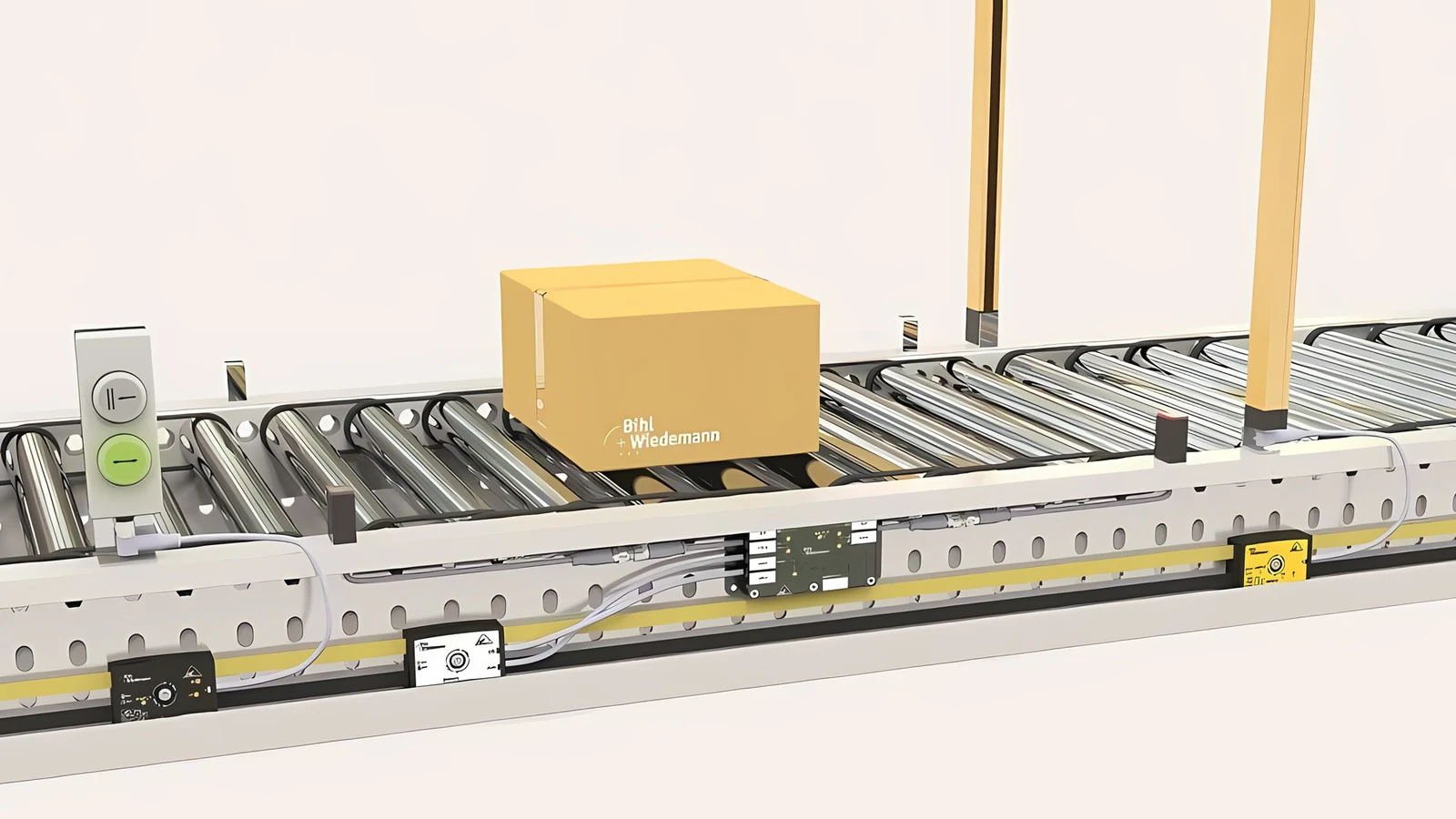
Bihl+Wiedemann’s official IP67 installation page compares two main connection methods. The yellow ASi profile cable is used for data transmission and ASi power supply, while the black AUX profile cable provides auxiliary power; both can be connected to the appropriate modules using a piercing connection technology. The geometry of the cables reduces the risk of reverse polarity; they can be laid out in the required length on reels and the field modules can be installed at any desired location. For the round M12 cables, a T-piece, pre-cut cables of the required length, and matching connectors are needed to create the necessary connections. The advantage of M12 cables is their widespread availability and the fact that they are detachable; profile cables, on the other hand, offer greater flexibility in terms of topology and installation.
Profiled cables and M12 connectors are not mutually exclusive options; they can be used together in the same installation via a passive distributor or the appropriate module. It is possible to take advantage of the higher conductive cross-section of profiled cables for main circuits, while using M12 connectors for short-distance device connections. However, whenever the cross-section changes, the current-carrying capacity and short-circuit protection parameters must be recalculated. The fact that two M12 connectors can be physically connected does not imply that they also provide electrical protection.
Design sequence for IP67 field installations
- Separate different machine areas: Mark areas that are dry, wet, require washing, are hot, subject to vibration, or are in motion on the layout diagram.
- Group the signals together: Cluster standard digital, safe, analog, IO-Link, and drive signals based on physical proximity and location.
- Establish an ASi/AUX topology: Draw the yellow data-energy line, and the black auxiliary energy line if necessary, along with their respective connection points.
- Calculate the voltage drop: Control should be performed via the longest path, under the highest simultaneous load, and within the permitted minimum device voltage range.
- Select branch protection: Protect conductor and connector current limits at every transition to thinner round cable or an M12 connection.
- Plan the mechanical installation: Specify the module base, cable direction, bending radius, service clearance, labeling requirements, and impact protection measures.
- Define the acceptance test: Predefine the criteria for torque, sealing, address assignment, I/O operations, short-circuit detection, AUX signal loss, and post-cleaning inspection.
Piercing technology and reliable contact on profile cables
In the piercing connection technology, the contact needles pass through the insulation of the profiled cable in a controlled manner to reach the conductor. The manufacturer’s application notes specify that the needles penetrate the cable at a perpendicular angle and that each conductor has multiple contact points. The repeatability of this design is ensured only when the mounting surface is clean, the cable is in the correct position within the channel, and the upper and lower parts of the body are securely fastened according to the manufacturer’s instructions. Forcing the cable in different directions, pressing foreign objects into the channel, or failing to properly close the body can all compromise the contact integrity and the cable’s sealing properties.
When the module is relocated, the method for dealing with the remaining holes in the profile cable must be determined in accordance with the approved accessory and installation instructions of the system being used. Random applications of fillers, tapes, or adhesives do not guarantee electrical and environmental compatibility. If the cable is damaged, it is essential to check the condition of the conductors and the insulation, rather than merely examining the outer surface. The unique geometry of the profile cable does not provide any mechanical protection against sharp edges in the cable channel, excessive pulling, or unauthorized bending.
BWU4230: an IP67 module for high-density field I/O
BWU4230 is a self-configuring ASi-5 field I/O module with eight M12 sockets and ASi/AUX profile-cable piercing connections. Depending on configuration, it offers up to 16 digital inputs and 16 electronic digital outputs with Y or mixed M12 wiring. Carrying two signals per M12 connection can reduce cable count, but pin assignments must match the sensor cable.
On the family data page dated April 13, 2023, for the BWU4230 model, the following specifications are listed: a nominal voltage of 30 V for ASi signals, 24 V for AUX signals; one ASi-5 address; two bytes of process data; and an IP67 protection rating. The physical dimensions of the device are 60 × 152 × 34 mm. The current values for sensors and outputs depend on the temperature; the total current limits change at +45 °C, +55 °C, and +70 °C. Although a current value of 0.35 A is specified for each output, the total output current, as well as the currents for sensors and shared input/output channels, are also subject to limitations. The mention of “16 channels” does not imply that 16 high-current loads can be operated simultaneously.
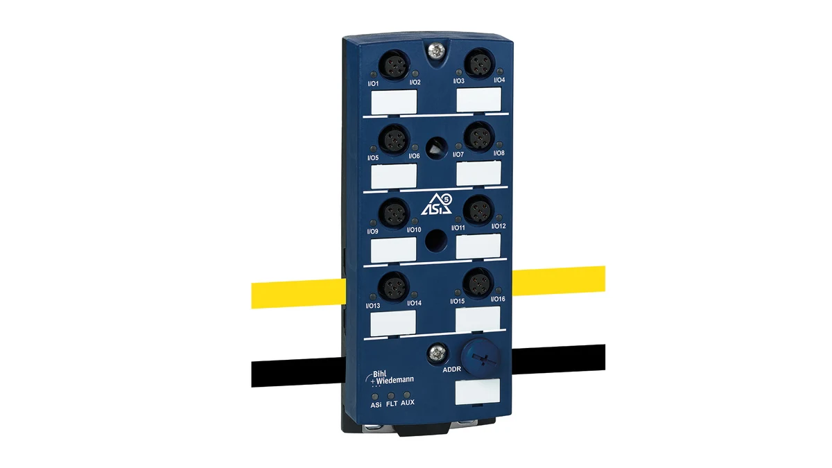
The lower component of the module is not included in the delivery; the method of installation and the selection of accessories must be ordered separately. This detail indicates that it is insufficient to list only the electronic upper module in the quotation and installation specifications. The data sheet also contains special notes regarding the use of AUX channels with passively safety-locked functions, which is possible starting from a specific identification number of the BWU4230. In safety-related designs, the actual production status/identification of the device, as well as current regulatory requirements, must be taken into consideration, rather than the product family name.
BWU4393: collecting safe and standard signals at the same field point
BWU4393 is an ASi-5 Safety input module with four M12 sockets. It supports four single-channel or two dual-channel safety inputs for potential-free contacts. With suitable system design, dual-channel use supports applications up to Category 4, PL e and SIL 3; the stated single-channel limit is SIL 1, Category 2 and PL c. Standard inputs and electronic standard outputs depend on configuration.
These ratings do not in themselves guarantee that the module, on its own, will ensure the overall performance level of the entire machine. The sensor architecture, wiring, cross-talk detection, testing methods, safety monitoring systems, safe outputs, end components, and restart behavior must all be verified in conjunction with a thorough risk assessment. The BWU4393 is designed for use with potential-free contact inputs; it should not be assumed that a safety sensor utilizing an OSSD (semiconductor-based safe output signal) can be connected in the same manner.
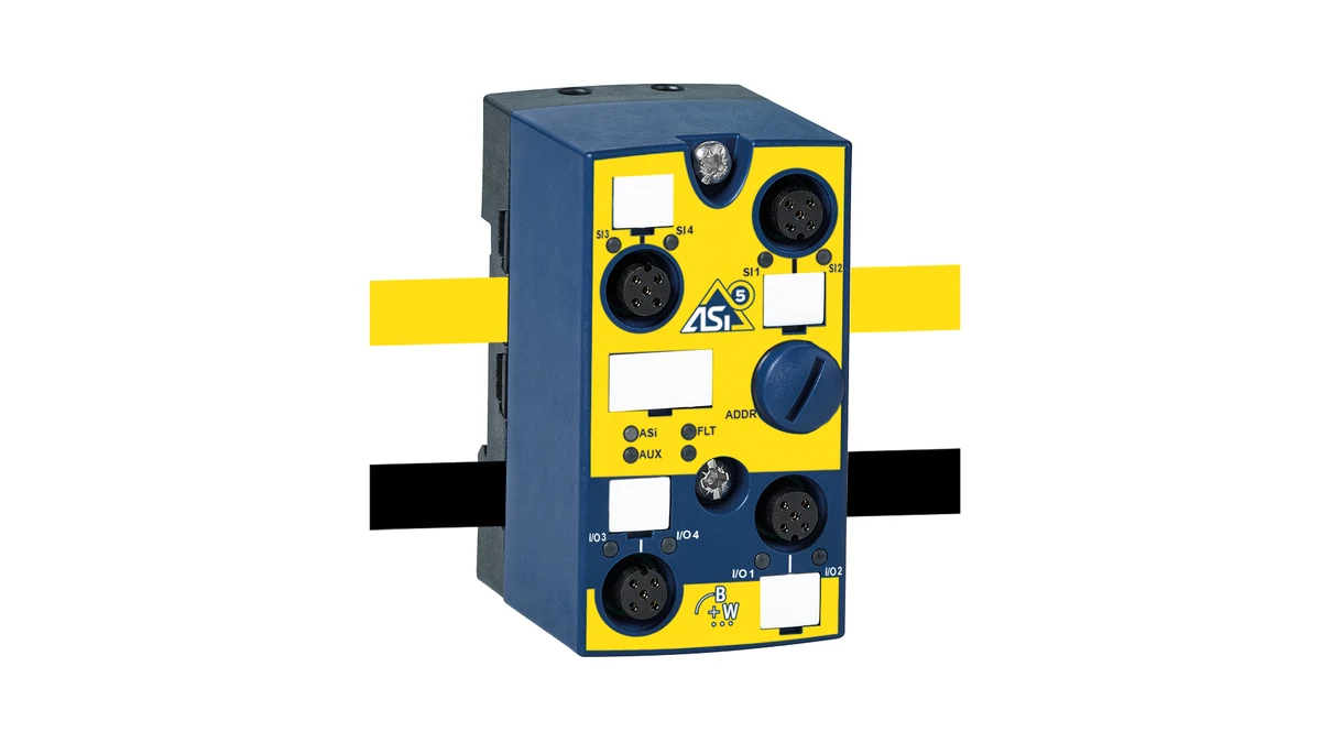
The data page dated January 8, 2026 specifies the following features: profile cable connection, an ASi-5 address, a maximum of 15 m of I/O connection cables, IP67 protection rating, and a body size of 45 × 80 × 56 mm. The ambient temperature range is indicated as −30 to +55 °C in the general table; in certain applications, it can extend up to +70 °C. For UL certification in the USA and Canada, the maximum temperature limit is +55 °C. The exposed M12 sockets must be covered with appropriate caps. Additionally, this product is not suitable for use in a passively safe switched AUX circuit; this restriction must be carefully considered in applications involving power-off functions.
BW3524: a passive transition from profile cable to a thin branch
BW3524 is a 19 mm-deep passive distributor that internally bridges two ASi profile-cable connections and provides a 5 m round-cable/connection-wire outlet. It is an IP67 flat-housing product suitable for cable ducts. The 20 January 2026 data sheet specifies 60 × 45 × 19 mm dimensions, 10–32 V DC PELV operating voltage and a maximum cable tensile load of 10 N.
A passive distributor is not a communication node: it has no ASi address and does not replace an I/O module that processes signals in software. Its role is connection and power distribution. BW3524 has no internal fuse. The family data sheet specifies limits up to 8 A for the profile-cable/piercing branch and up to 4 A for round cables or connecting wires. Coordinate source and branch protection to protect the smallest conductor in the actual circuit.
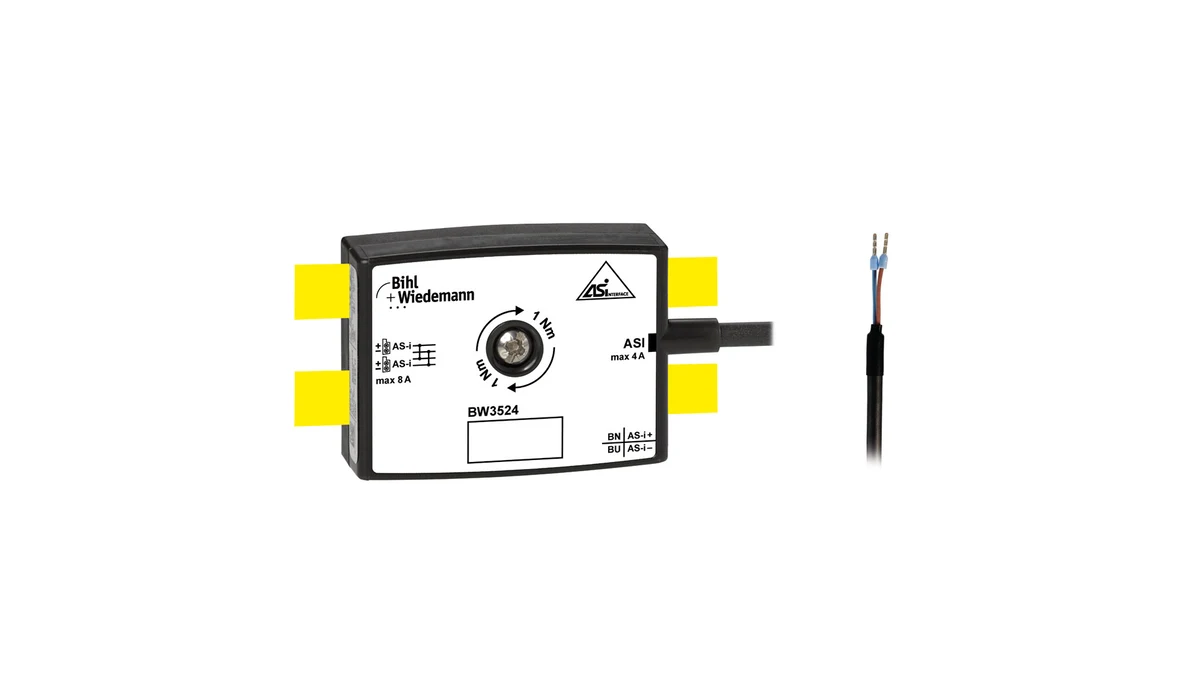
The IP67 classification depends on the fact that the corresponding cable connections also meet the IP67 requirements. The environmental specifications within the UL framework, as well as the details provided in the manufacturer’s IP declaration on the evaluation page, are also relevant in this regard. The temperature range required for fixed and flexible mounting methods is not the same; the cable’s performance was tested only under fixed-mounting conditions at −30 °C. These details emphasize that not even the smallest passive components should be selected without thoroughly reviewing the entire field specification.
The three products have different functions
| Product example | Main task | Critical installation check | Incorrect assumption |
|---|---|---|---|
| BWU4230 | Transferring standard digital field I/O devices to the ASi-5 platform | Channel configuration, M12 connectors, AUX load, sub-module, and current reduction depending on temperature. | Assuming 16 inputs and 16 outputs operate independently at full current simultaneously |
| BWU4393 | Collecting potential-free safety contacts and standard I/O | Single/dual channels, PL/SIL classification, AUX architecture, and open port covers. | Assuming an IP67 or Safety label alone validates the whole safety function |
| BW3524 | Passive distribution from profile cable to round cable or individual wires | Current protection, cable pulling load, IP-compliant connection terminals, and cross-sectional dimensions of wires | Assuming a passive distributor is an I/O module or has an internal fuse |
Cable protection and voltage drop
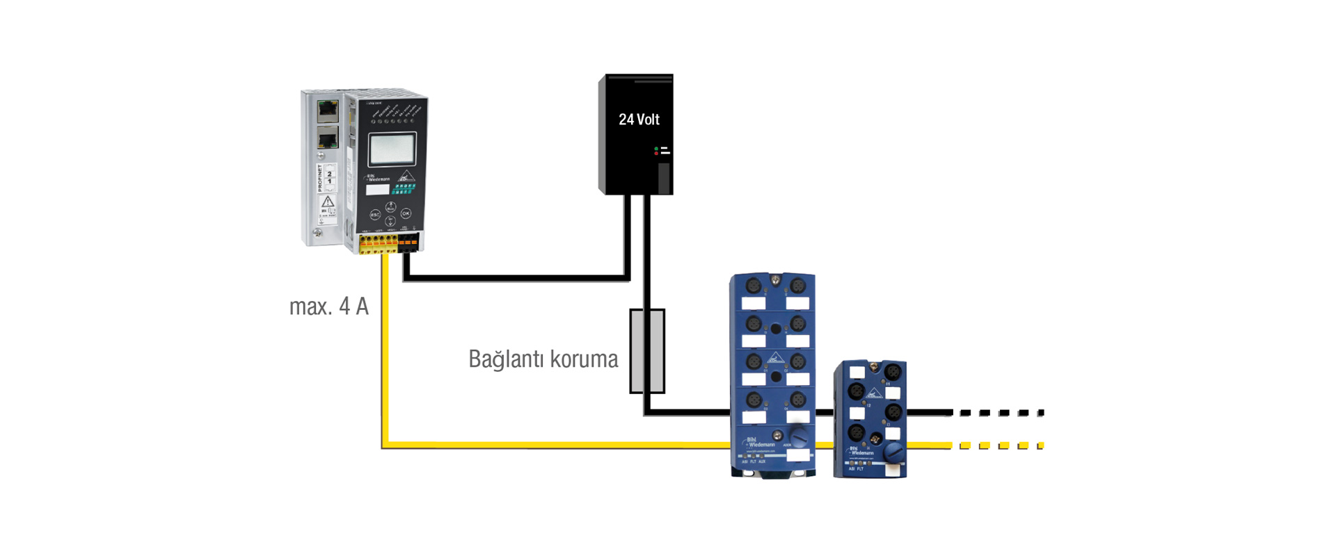
The manufacturer describes ASi profile-cable options with 1.5 mm² and 2.5 mm² conductors. M12 round cables may have smaller conductors. When branching from a main profile cable to a thinner line, select protection for the weakest conductor and connector as well as total load current. Some gateways or distributors provide fuse functions; verify exactly which line is protected and at what rating.
The voltage drop is calculated not only based on the total length of the cable but also on the actual path that the current follows and the type of return conductor used. The manufacturer’s specification for 24 V ASi systems recommends that the 50-meter limit should not be exceeded due to voltage drop when using a standard 24 V power source. However, this is not a universal or fixed distance requirement for all ASi projects; the optimal distance may vary depending on the power supply voltage (e.g., 30 V), the use of repeaters, terminators, cable cross-section, and the overall network topology. The appropriate project design should be determined by referring to the latest documentation regarding gateway, power supply, and network configuration guidelines.
Managing M12 connections and protective caps
The term “M12” merely refers to the thread size of the connector. Additional information such as the coding system (A, B, D, X, etc.), the number of pins, the male/female configuration, as well as the electrical and signal functions must also be matched accordingly. Even if the connectors appear to fit visually, incorrect pin assignments can cause short circuits in the sensor power supply. The cable labels at both ends and the module socket labels must correspond to the specifications in the electrical diagram. If a Y-cable is used, the documentation must clearly indicate which pins carry the two signals and how they should be disconnected in the event of a fault.
For proper sealing, the seal surface must be clean and undamaged; the connectors must be tightened using the torque recommended by the manufacturer, and the cable body must not be kinked. Simply tightening the connectors by hand until they feel “firm” does not constitute a reliable quality control method. Unused ports should be covered with appropriate protective caps; transport caps must not be confused with permanent IP seals. For connectors that have been removed and reinstalled, their seals and contacts must be inspected, and no residues of cleaning chemicals should remain on the sealing surfaces.
Mechanical layout and service access
It is not sufficient for the IP67 module to be simply screwed onto the machine. The accessibility for installing and removing M12 connectors, the minimum bending radius of the cable, the accessibility for addressing, the visibility of the LEDs, and the opening direction of the sub-module mechanism must all be verified in the CAD layout. In areas where the module may be subjected to impacts from forklifts or products, additional protection measures may be required. The drainage design should ensure that water accumulating on the surface does not continuously press against the connectors, and it is essential to prevent any uninterrupted upward or downward movement of water along the cable that could cause damage to the module.
When the profiled cable is unwound from the reel, it should not become twisted or bent sharply; products that do not possess movable cable features should not be installed on the cable carrier system. The fixing clamp must not crush the insulation or generate any tensile stress in the immediate vicinity of the body. For cable-equipped products like the BW3524, the manufacturer’s specified maximum tensile load of 10 N clearly indicates that such cables should not be used for mechanical support purposes.
Functional safety and AUX zones
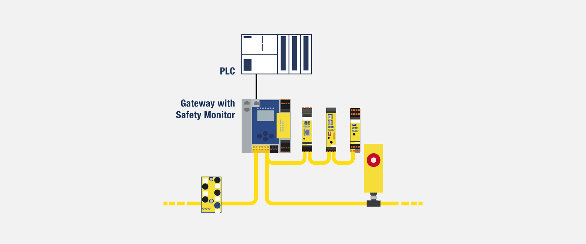
ASi Safety allows safe and standard signals to be transmitted over the same network infrastructure; however, the assumptions regarding energy distribution remain separate. To safely disconnect a secondary power supply, it is necessary to consider the cable connections, internal module connections, and external power supply paths within the load. The notes provided for the passive, safety-switched AUX pathways in the BWU4230 and BWU4393 models differ. Even if they belong to the same blue-colored family of products or have the same IP rating, this does not guarantee identical safety functionality.
If the safety input cable shares the same M12 connector as the standard output cable, the potential risks associated with the use of Y-shaped or mixed-pin connections must be included in the risk analysis. It is essential to verify the diagnostic capabilities of the selected monitor in cases such as cable compression, simultaneous short-circuiting of both channels, or cross-connection between different voltage levels. During acceptance testing, it is not sufficient to merely verify that the machine stops when the emergency stop button is pressed; instead, tests should also cover single-channel failures, cable disconnections, re-starting processes, and the device’s error-locking mechanisms.
Commissioning checklist
- Match the product number with the sub-module, protective cover, M12 cable, and profile cable material lists.
- Ensure that the ASi/AUX cables are connected in the correct channel and with the correct polarity, and that the terminal contacts are closed in accordance with the manufacturer’s specifications.
- Verify the protective components, their settings, and selectivity for the profile cable and M12 connectors on the schematic diagram.
- Complete the checks for insulation, short circuits, grounding, and pin connections without supplying power.
- Measure the supply voltages at remote locations within the network when it is idle and under the highest simultaneous load conditions.
- Exercise the physical I/O at every address; record standard and safety-channel tests in separate protocols.
- In the event of errors such as short circuits, AUX signal loss, ASi interruptions, or open ports, verify that the LED indicators and the PLC are emitting alarms.
- In cases where it is necessary, repeat the visual inspection and electrical function tests after cleaning or exposure to water.
Maintenance and change management
During periodic inspections, it is necessary to check for loose connectors, missing caps, cracked bodies, crushed profiled cables, damaged branches under tensile stress, worn labels, and signs of water damage. LED testing serves as an initial step in identifying faults; measurements should be taken if contact resistance or voltage drop is suspected. When replacing a module, the procedure for transferring the previous address and channel configuration must be strictly followed, and it must be confirmed that the new module is truly equivalent in terms of sub-modules and pin assignments.
When a module is added to the field later on, it is not sufficient to simply connect it to an empty cable port. The node capacity, process data profile, power budget, fuses, PLC data map, and safety certifications must all be rechecked. The status of any unused, previously drilled holes must be managed in accordance with the manufacturer’s instructions. If the as-built topology is not updated, the physical flexibility of the ASi system may result in invisible branches or incorrect load calculations.
Information to share for a quotation
- Machine layout, IP protection rating, cleaning methods, temperature, vibration, and chemical exposure.
- Standard/safe I/O counts, types of sensor connections, and M12 pin layouts
- ASi and AUX topologies, cable cross-sections, total/branch lengths, and power supply points
- Each load’s nominal, starting and worst-case current, and simultaneous-operation scenario
- Passively safety-switched AUX areas and the required PL/SIL targets
- Profile cables, M12 connectors, branch fuses, connector coding systems, and spare ports.
- Mounting surface, service accessibility, risk of impact, and conditions regarding cable pulling/bending.
- Commissioning, water/purity acceptance testing, maintenance interval, and spare parts strategy.
Oskon designs Bihl+Wiedemann IP67 installations as complete connection and power systems before selecting individual modules. BWU4230, BWU4393 and BW3524 are examples from the current official portfolio, not automatic solutions for every application. Confirm the final selection against the full product number, quotation-date data sheet, country-specific approvals, mating connector and actual environmental conditions.