Industrial image processing is a much more complex engineering task than simply placing a camera on a production line. Various factors must be considered together: which characteristics of the part need to be measured, whether 2D contrast is sufficient, whether height or volume information is required, the part’s movement speed, the field of view, the minimum tolerances that must be detected, as well as lighting, optics, triggering mechanisms, data processing, and how to identify defective products. This guide explains the steps involved in making the right technical choices for implementing the right architecture, using specific product families from SICK’s range of 2D and 3D machine vision solutions. The technical specifications provided should be understood in the context of the particular product family mentioned.
Start with the decision required before deciding what the camera should see
A successful vision application begins with measurable acceptance criteria that distinguish good parts from bad ones. The phrase “inspect the label” could refer to verifying the label’s presence, the correct product code, the readability of the printing, the positional tolerances, or the accuracy of the color. Each of these tasks requires different image quality and processing tools. Similarly, the requirement “take measurements” might involve determining the 2D dimensions of the outer contour, the surface height, or the three-dimensional volume of the object. Choosing a camera model without specifying the error tolerance, acceptance limits, minimum defect size, types of products involved, or cycle time relies on hardware assumptions rather than technical requirements, which can limit the effectiveness of the solution.
A sample set should not consist solely of flawless parts. It should include elements representing normal production variations, different batches of supplied materials, permissible differences in color and surface texture, parts that are marginally acceptable, as well as actual defects. Materials such as shiny metals, transparent packaging, dark rubber, and reflective foil behave differently under the same lighting conditions. An image processing algorithm can only produce reliable results if the optical signals it receives are sufficient. Therefore, the selection of the camera and the lighting conditions are determined in parallel—since it cannot be assumed that the software will be able to completely compensate for poor-quality images.
Distinguish 2D and 3D approaches correctly
2D imaging treats the scene as a grid of rows and columns, represented by intensity or color values. It provides a powerful and often cost-effective solution for inspections involving edges, holes, patterns, codes, colors, positions, and shapes. However, if the distance of the object from the camera changes, resulting in variations in perspective or scale, telecentric optics, mechanical guides, or calibration may be required. In cases where errors are caused solely by differences in height, where objects of the same color need to be distinguished, or where measurements of volume and flatness are necessary, 3D data is more appropriate.
3D is not a single technology. Laser triangulation-based line-profile cameras create a detailed height map by capturing successive profiles of a moving object. The frequency of profile measurements, the speed of the moving object, and the resolution of the encoder determine the sampling rate along the object’s movement direction. Time-of-flight-based snapshot cameras, on the other hand, generate distance and intensity data for the entire scene in a single frame, which can be useful for applications such as robotics, logistics, and environmental monitoring. The micrometer-level precision of line-profile cameras and the wide-field scanning capability of snapshot cameras are not designed to serve the same specific purposes.
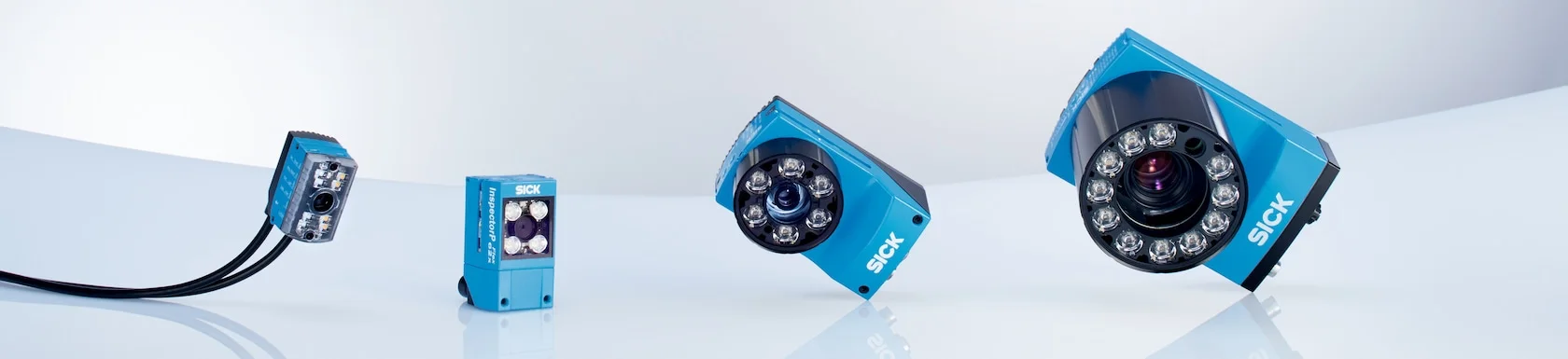
Decision table for three architectures
| Approach | Core data | Typical task | Critical project question |
|---|---|---|---|
| Compact 2D vision sensor | Monochrome or color 2D images | Presence, orientation, pattern, color, OCR/code, dimensions, and position | Is the defect visible with stable lighting and sufficient pixel resolution? |
| Line-profile 3D camera | Height, reflection, and relevant profile data generated during the movement. | Surface, height, shape, volume, and precise 3D measurements. | Are the profile rate, field of view, and height resolution compatible with the belt speed? |
| 3D snapshot time-of-flight camera | Depth and intensity frame of the full scene | Pallets/loads, robotics, environmental perception, occupancy, and gross volume. | Does it meet the requirements regarding working distance, reflectivity, field of view, and frame rate? |
This table is for preliminary screening purposes. For example, if a label is required to have both the correct color and the appropriate embossing height, two different types of data may be needed. If the surface of the part cannot be fully detected without rotating it under the camera, multiple cameras or mechanical manipulation may be required. While expanding the field of view facilitates installation, it reduces the number of pixels per object at the same sensor resolution. Every decision must be verified through actual image analysis and cycle testing, with attention paid to even the smallest potential errors.
InspectorP61x for compact 2D inspection
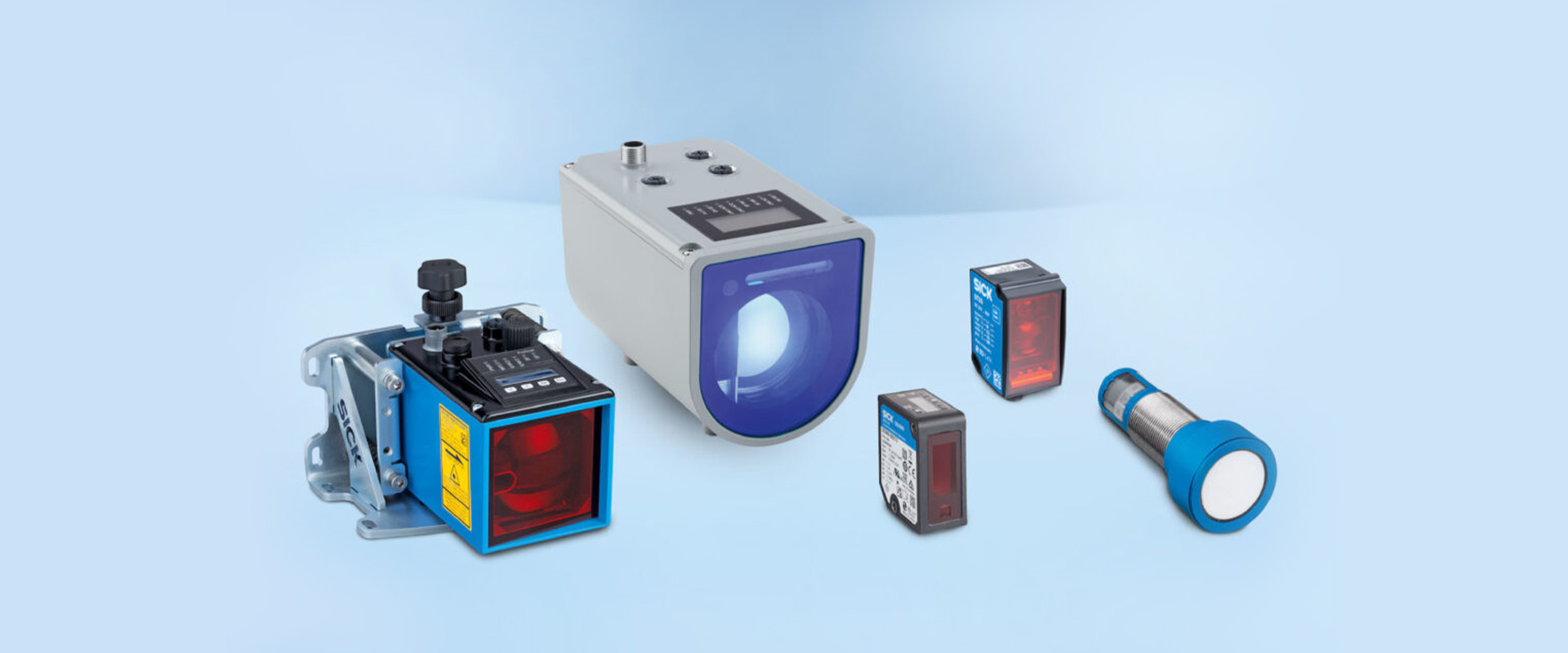
The InspectorP61x is described on SICK’s official website as an ultra-compact 2D vision sensor designed for in-line inspection of small parts, assemblies, and finished products. Its compact size makes it ideal for installation in confined spaces or on robotic end-effectors. The integrated optics allow for precise adjustment of the illumination in terms of brightness, color, and pattern, enabling the sensor to generate high-quality images without the need for additional components. This family of sensors offers both monochrome and color imaging options, as well as NIR versions and variants with liquid-lens technology and IP65 protection levels; the specific configuration depends on the application requirements.
The SICK Nova Quality Inspection tools offered with the product enable the configuration of rule-based inspections via a web interface. For tasks such as color classification, component presence detection, orientation verification, detail inspection, dimension measurement, location checking, or quality control, deterministic criteria can be used initially. Optional Intelligent Inspection tools can enhance classification processes or anomaly detection tasks when trained with sample data. However, the use of artificial intelligence does not eliminate the need for acceptance criteria and validation processes; it is still essential that the training data reflect the diversity of production conditions, and that the accuracy of acceptance/rejection decisions be verified using a separate test set.
In a 2D application, the pixel budget must be allocated appropriately between the field of view and the ability to detect the smallest details. For example, when the camera is moved away to capture the entire surface of a plate, a small scratch may be detected by only a few pixels, making it impossible to make a reliable identification. The optical focus, depth of field, and working distance are selected taking into account mechanical tolerances. If the exposure time is shortened to prevent motion blur of moving parts, more light may be required. If the integrated lighting is insufficient, external backlights, ring lights, spot lights, or coaxial illumination systems should be tested on the sample.
Ruler3000 for high-speed 3D profiling
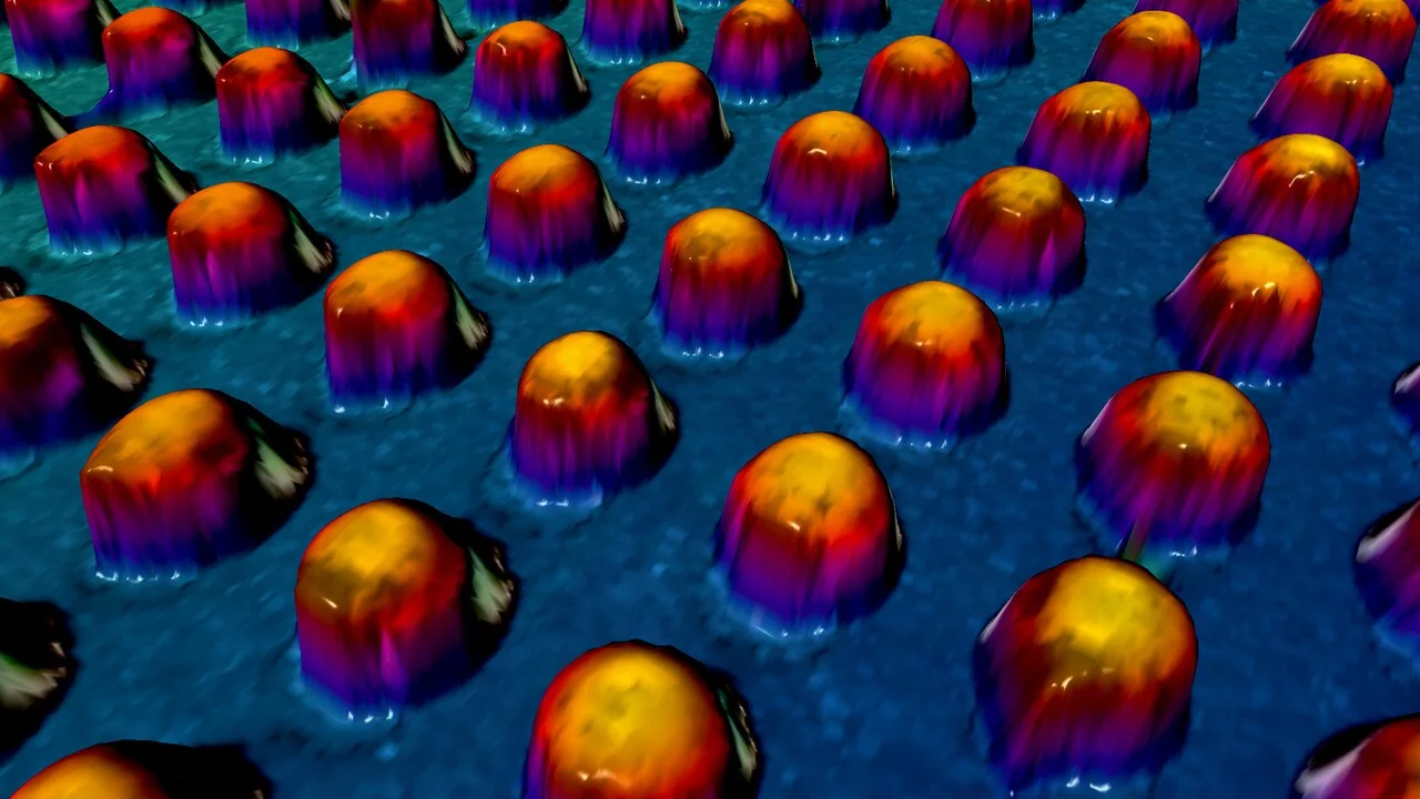
The Ruler3000 is a family of factory-calibrated 3D profile cameras that use laser triangulation. According to SICK’s current product page, these cameras offer a 3D profiling speed of up to 46 kHz under specific conditions, with the ability to capture up to 3,200 data points per profile. Certain models in this family can achieve a resolution of up to 0.8 µm; however, this figure does not represent the common performance of all models within the series. The product portfolio includes models with various field of view widths, ranging from approximately 27 mm to 1.7 m, thus covering a wide range of application scales—from small electronic components to larger materials.
The camera integrates the laser, optics, and calibration components within a standardized housing. Compatibility with GigE Vision and GenICam facilitates standardized software integration; the manufacturer also provides Stream Setup and GenIStream tools. The IP65/IP67 rating of the industrial housing is specified in the product family overview. The choice between red or blue laser and a laser class of 2 or 3R should be determined based on material properties and speed requirements. Since the laser class directly affects mechanical protection measures, accessibility, labeling options, and risk mitigation strategies, it cannot be considered solely on the basis of image quality.
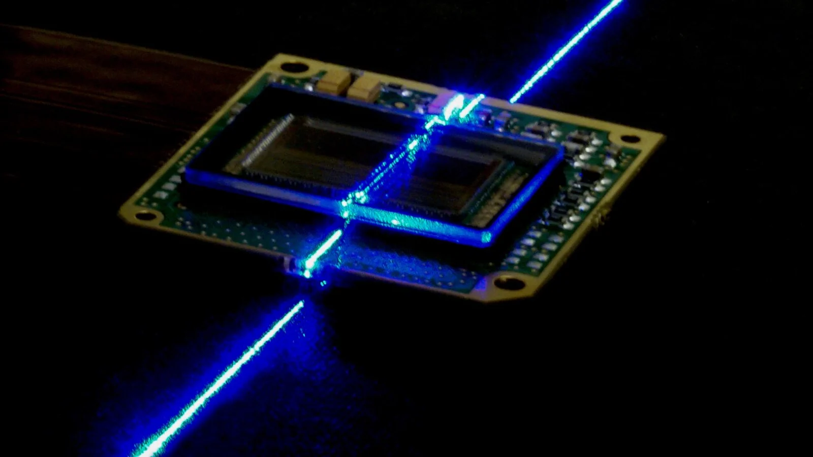
In line-profile measurement, the camera captures only a single cross-section of the object; the three-dimensional surface is determined by the controlled movement of the object or the camera. In the absence of encoder data, changes in the belt speed can distort the measurement results in the direction of movement. The position of the trigger sensor ensures that the initial and final profiles are captured at the correct locations, while the profile spacing ensures that even the smallest defects are not missed. The presence of both bright and dark areas in the same scene can pose challenges to exposure control. The dual-exposure and related processing options available in the Ruler3000 series can be utilized for such scenarios, but it is essential to conduct measurement tests with actual materials.
Visionary-T Mini for scene depth
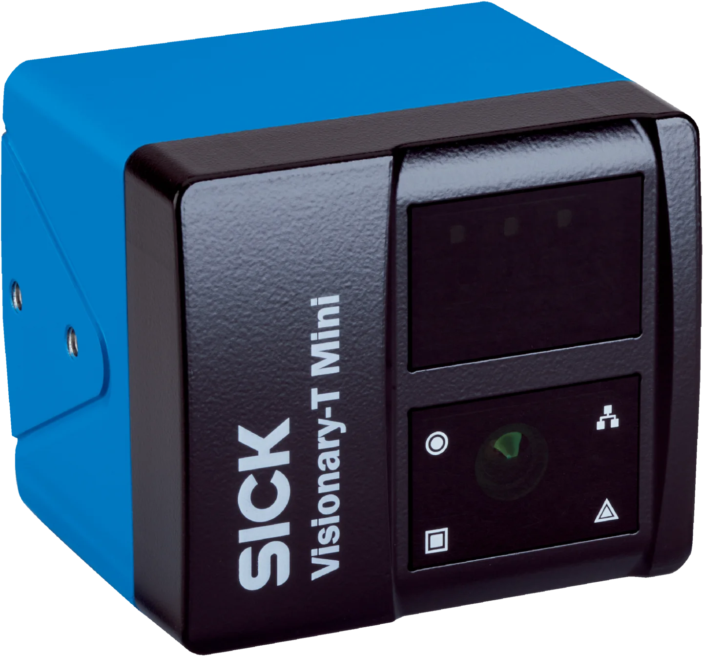
The Visionary-T Mini is a compact 3D snapshot camera series that utilizes time-of-flight technology. It generates distance and intensity data for each pixel, making it ideal for a wide range of applications such as monitoring conveyor belt fill levels, measuring package or pallet dimensions, performing robotic positioning tasks, and detecting the presence of objects in industrial environments. According to SICK’s official product page, this series offers a resolution of 512 × 424 pixels, the ability to capture up to 30 3D images per second, a temperature range of −10 °C to +50 °C, IP65/IP67 protection levels, and support for 3D data transmission over industrial Gigabit Ethernet.
Within this family, there are two main approaches: CX and AP. The CX variant provides rapid access to data for external evaluation, while the AP variant enables applications to be loaded onto the camera and data to be processed locally on the device, all within the SICK AppSpace framework. The decision of whether to perform the evaluation on the camera or on an industrial PC should be based on factors such as network bandwidth, latency, maintenance requirements, software responsibility, and the desired type of output. A robot application using a continuous point cloud requires a different architecture from an inspection application that simply sends a pass/fail signal to the PLC.
The performance of time-of-flight measurement can be affected by the reflectivity of the target, ambient light, operating distance, viewing angle, and the presence of overlapping edges. Bright metals, black surfaces, extremely thin objects, or layers that overlap each other must be tested using actual samples. If multiple cameras are used, it is necessary to carefully design the coverage area, blind spots, common coordinate system, and data fusion method. The highest frame rate listed in the catalog does not necessarily guarantee the same fast response time in practical applications, depending on the selected data filtering criteria and communication protocol.
Lighting, optics and mechanical design
In 2D image quality, the direction of light is often more decisive than the camera itself. Backlight helps to highlight outlines and holes; low-angle dark-field lighting can emphasize surface textures; whereas diffused or dome-shaped lighting can reduce harsh reflections on shiny surfaces. In applications where color accuracy is critical, the light spectrum and the camera’s color settings must be fixed. Components such as polarizers, filters, and protective lenses can be useful, but they also come with associated light losses and maintenance requirements. In environments where ambient lighting changes throughout the day, uncontrolled daylight must be filtered out.
The camera bracket serves as the mechanical reference for the image coordinate system. Vibration, bending, or reinstalling the camera at a different angle after maintenance can disrupt measurement accuracy. The mounting design must be rigid and adjustable; the focus and aperture settings should be lockable. Access must be provided to clean the lens or protective cover. The distance tolerance between the camera and the part must be kept within the specified range. In a 3D laser system, the viewing paths of the camera and laser should not be blocked. In a 3D snapshot system, blind spots created by surrounding structures should be analyzed through CAD simulations and physical tests of the setup.
Software, recipes and line integration
An image processing algorithm is not merely composed of a single threshold value. Preprocessing steps, the area of interest, reference detection, measurement tools, classification processes, and decision-making logic must all be organized in a structured, traceable “recipe.” To ensure that the correct algorithm is applied during product changes, the PLC and the camera must perform mutual verification. The management of changes to the algorithm name, version, camera software, and acceptance criteria is also crucial. Limiting unauthorized parameter adjustments and backing up existing settings are just as important for the long-term reliability of a vision system as the initial setup process itself.
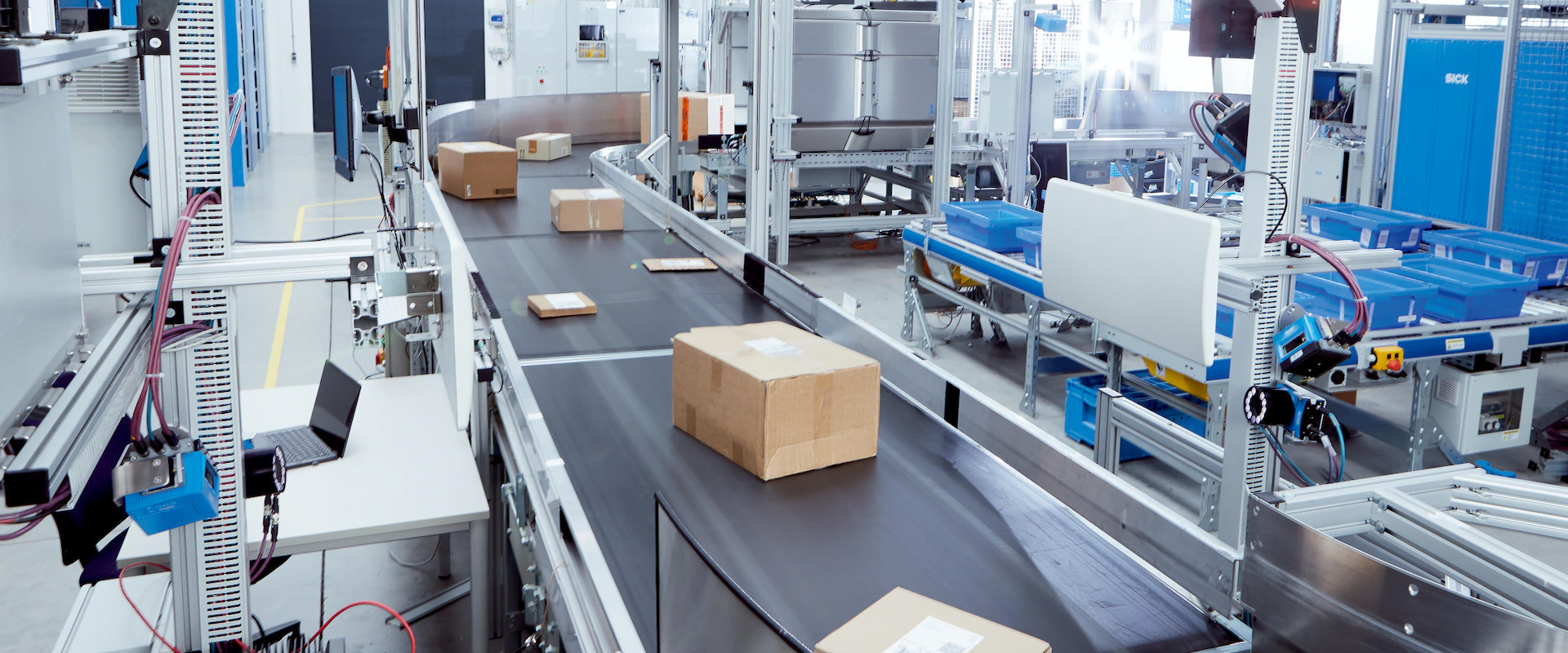
Time and part tracking are required between the moment of activation and the actual physical separation of the part. Once the camera captures the image, the part continues to move along the conveyor belt. The total delay is comprised of the evaluation time, the PLC cycle time, the network latency, and the response time of the actuator. If multiple parts pass by in succession, it is essential to ensure that the results are correctly associated with the corresponding parts. For ambiguous situations such as “no read”, missing images, incorrect positioning, or network interruptions, a well-defined error handling mechanism should be in place instead of accepting the parts as valid. Storing erroneous images and relevant decision-making metrics facilitates the analysis of the root causes of these issues.
When does artificial intelligence make sense?
Rule-based measurement enables clear and controllable verification of established tolerances regarding diameter or position. When the shape of defects is variable, the appearance of normal products varies widely, or it is difficult to manually define rules, sample-based artificial intelligence tools can prove highly effective. The Intelligent Inspection solution and the SICK Nova ecosystem available for the InspectorP61x support this approach in tasks such as classification and anomaly detection. However, the number of training images alone does not constitute a reliable quality indicator. It is essential to include samples representing various production variations, rare defects, different backgrounds, lighting conditions, and various shifts.
The validation set is separated from the training data; the rates of false rejections and false acceptances are evaluated based on their impact on business operations. Instead of automatically accepting cases at the boundary, the model’s confidence score can trigger a re-examination process. When there is a change in packaging, supplier, or surface characteristics, the model’s performance is measured again. Wherever possible, the results generated by artificial intelligence are combined with rule-based tools such as codes or location data. This ensures that the learned features and established technical requirements can both be taken into account when making decisions.
Data package for quotations and feasibility studies
- Definition of acceptance/rejection criteria for each feature to be monitored, along with measurable tolerances where applicable.
- Good, defective, and borderline samples; variations in batch, color, surface, and shift patterns.
- Part dimensions, viewing direction, smallest defect, camera distance, and available mounting space
- Line speed, cycle time, part interval, stop-and-go or continuous motion, and trigger source.
- Whether 2D color/monochrome, 3D profile, or 3D snapshot data is required, along with the desired measurement results.
- Ambient light, reflectivity, dirt, dust, washdown, temperature, vibration, and enclosure requirements
- PLC/network protocol, result bits, recipe management, data storage, and connection to the higher-level system
- Logic for identifying defective products, behavior in the event of ambiguous results, and required duration of traceability.
The feasibility report should not merely consist of the statement “observed.” Information on the samples used, the camera/optical system/light configuration, the operating range, exposure settings, field of view, measurement repeatability, cycle time, and error margins must be documented. When transitioning to mass production, the laboratory setup details are converted into mechanical drawings and part lists. Only in this way can a successful demonstration be transformed into a reproducible industrial solution.
Commissioning acceptance and lifecycle
During the installation acceptance process, the measurement system analysis approach is utilized to examine repetitions of the same component, different components, as well as operator and shift-related factors. The results obtained by the vision system are compared with reference measurements or approved sample specifications. Tests are conducted at minimum and maximum line speeds to evaluate issues such as missed detections, image distortion, and result delays. Error scenarios such as network interruptions, incorrect recipes, and camera contamination are also simulated. The accepted parameters are documented, and appropriate authorization levels for making adjustments are defined.
Maintenance plan: This includes regular inspections of the optical window cleanliness, lighting conditions, bracket tightness, as well as the trends in image focus/contrast levels and instances of incorrect decisions. Since the effects of lighting degradation or changes in the product surface progress gradually, relying solely on system alarms may not be sufficient. Instead, the trend of image quality is monitored using reference samples or tracking metrics. This approach transforms the investment in cameras into a reliable source of quality data, rather than a one-time inspection tool.